EP0091582B1 - Dispositif pour étirer des piles de produits pliés mutuellement déplacées transversalement par rapport à la direction de transport - Google Patents
Dispositif pour étirer des piles de produits pliés mutuellement déplacées transversalement par rapport à la direction de transport Download PDFInfo
- Publication number
- EP0091582B1 EP0091582B1 EP83102911A EP83102911A EP0091582B1 EP 0091582 B1 EP0091582 B1 EP 0091582B1 EP 83102911 A EP83102911 A EP 83102911A EP 83102911 A EP83102911 A EP 83102911A EP 0091582 B1 EP0091582 B1 EP 0091582B1
- Authority
- EP
- European Patent Office
- Prior art keywords
- belt
- transport
- clamp
- belts
- guide
- Prior art date
- Legal status (The legal status is an assumption and is not a legal conclusion. Google has not performed a legal analysis and makes no representation as to the accuracy of the status listed.)
- Expired
Links
- 230000007246 mechanism Effects 0.000 claims 4
- 230000002596 correlated effect Effects 0.000 claims 2
- 230000005540 biological transmission Effects 0.000 claims 1
- 230000008859 change Effects 0.000 description 3
- 230000000694 effects Effects 0.000 description 2
- 238000012423 maintenance Methods 0.000 description 2
- 230000007257 malfunction Effects 0.000 description 2
- 238000004519 manufacturing process Methods 0.000 description 2
- 230000000717 retained effect Effects 0.000 description 2
- 230000008719 thickening Effects 0.000 description 2
- 238000010276 construction Methods 0.000 description 1
- 230000008878 coupling Effects 0.000 description 1
- 238000010168 coupling process Methods 0.000 description 1
- 238000005859 coupling reaction Methods 0.000 description 1
- 238000011161 development Methods 0.000 description 1
- 230000018109 developmental process Effects 0.000 description 1
- 238000006073 displacement reaction Methods 0.000 description 1
- 238000004806 packaging method and process Methods 0.000 description 1
- 238000005096 rolling process Methods 0.000 description 1
- 238000000926 separation method Methods 0.000 description 1
- 230000007704 transition Effects 0.000 description 1
- 238000011144 upstream manufacturing Methods 0.000 description 1
Images
Classifications
-
- B—PERFORMING OPERATIONS; TRANSPORTING
- B65—CONVEYING; PACKING; STORING; HANDLING THIN OR FILAMENTARY MATERIAL
- B65H—HANDLING THIN OR FILAMENTARY MATERIAL, e.g. SHEETS, WEBS, CABLES
- B65H29/00—Delivering or advancing articles from machines; Advancing articles to or into piles
- B65H29/66—Advancing articles in overlapping streams
- B65H29/6672—Advancing articles in overlapping streams dividing an overlapping stream into two or more streams
-
- B—PERFORMING OPERATIONS; TRANSPORTING
- B65—CONVEYING; PACKING; STORING; HANDLING THIN OR FILAMENTARY MATERIAL
- B65H—HANDLING THIN OR FILAMENTARY MATERIAL, e.g. SHEETS, WEBS, CABLES
- B65H29/00—Delivering or advancing articles from machines; Advancing articles to or into piles
- B65H29/66—Advancing articles in overlapping streams
- B65H29/6609—Advancing articles in overlapping streams forming an overlapping stream
-
- B—PERFORMING OPERATIONS; TRANSPORTING
- B65—CONVEYING; PACKING; STORING; HANDLING THIN OR FILAMENTARY MATERIAL
- B65H—HANDLING THIN OR FILAMENTARY MATERIAL, e.g. SHEETS, WEBS, CABLES
- B65H2301/00—Handling processes for sheets or webs
- B65H2301/40—Type of handling process
- B65H2301/44—Moving, forwarding, guiding material
- B65H2301/444—Stream of articles in shingled formation, overlapping stream
- B65H2301/4447—Stream of articles in shingled formation, overlapping stream multiple streams
- B65H2301/44474—Stream of articles in shingled formation, overlapping stream multiple streams interfolded
-
- B—PERFORMING OPERATIONS; TRANSPORTING
- B65—CONVEYING; PACKING; STORING; HANDLING THIN OR FILAMENTARY MATERIAL
- B65H—HANDLING THIN OR FILAMENTARY MATERIAL, e.g. SHEETS, WEBS, CABLES
- B65H2301/00—Handling processes for sheets or webs
- B65H2301/40—Type of handling process
- B65H2301/44—Moving, forwarding, guiding material
- B65H2301/447—Moving, forwarding, guiding material transferring material between transport devices
- B65H2301/4473—Belts, endless moving elements on which the material is in surface contact
- B65H2301/44732—Belts, endless moving elements on which the material is in surface contact transporting articles in overlapping stream
-
- B—PERFORMING OPERATIONS; TRANSPORTING
- B65—CONVEYING; PACKING; STORING; HANDLING THIN OR FILAMENTARY MATERIAL
- B65H—HANDLING THIN OR FILAMENTARY MATERIAL, e.g. SHEETS, WEBS, CABLES
- B65H2301/00—Handling processes for sheets or webs
- B65H2301/40—Type of handling process
- B65H2301/44—Moving, forwarding, guiding material
- B65H2301/447—Moving, forwarding, guiding material transferring material between transport devices
- B65H2301/44765—Rotary transport devices with compartments
Definitions
- the invention relates to a device for pulling apart sheets which are offset with respect to one another transversely to the transport direction, preferably of folded products transported in the form of a scale track over a transport route, with folded products arranged in the region of a section of the transport route on both sides of the product track, with the free edge of the respective facing offset Sheets which can be brought into engagement and are driven with the same holding device running in the transport direction, at least one of which also has a movement component running transversely to the transport direction.
- a device of this type is known from DE-PS 2 417 614. Since, in devices of this type, two folding products of the same or different thickness can be folded together and possibly trimmed, a second or a double-width folding device is unnecessary.
- the holding devices are designed as gripper rows which are each guided on an endless track and have grippers arranged next to one another, which grasp a respectively assigned sheet package at its free edge formed by the mutual offset and bring it into the desired lateral position.
- the disadvantage here is that the predetermined distance between the grippers requires a precise distance between the successive folding products.
- the grippers have a fixed mutual distance.
- each holding device which also has a movement component running transversely to the transport direction, as a band guide with its front end protruding laterally in relation to the transport direction and having a straight edge strip formed by the facing, offset by the sheet offset of the product web is formed through the clamping gap, which is delimited by mutually opposite, uniformly rotating clamping bands.
- each clamping gap on the side is delimited by at least two clamping bands rolling on one another advantageously results in an elastic, gap-free limitation of this clamping gap over its entire length and thus not only a particularly simple construction but also a particularly high degree of freedom from interference.
- the advantages that can be achieved with the invention can therefore be seen in particular in their simplicity and therefore overall in excellent economy.
- the clamping bands can advantageously be supported by pressure rollers arranged in the area between their deflection devices.
- the opposing pressure rollers of the lower and upper clamping band of a band guide can advantageously be offset from one another in the transport direction in order to ensure high elasticity in the region of the clamping gap. This ensures that thickenings in the area of the product flow can also be absorbed without disruption and readjustment.
- a further advantageous embodiment of the superordinate measures can consist in the fact that at least one clamping band, preferably all clamping bands of each band guide, are designed as toothed belts received on toothed belt wheels. These measures result in a non-slip
- the upper and lower clamping bands of each band guide can advantageously be connected to one another in terms of drive by means of a countershaft arranged in the region of a toothed belt wheel pair.
- the folding product 1 shown in FIG. 1 consists of two interlocking sheet packs 1a and 1b, which are laterally offset from one another, so that in the area of each side there is a free edge 2 with which one sheet pack projects above the other.
- the width of the edge 2 corresponds to the lateral offset.
- the two sheet packs 1a and 1b can be grasped and pulled apart, so that two separate folding products result, which can have the same or different number of pages.
- the production of these two folding products can, however, be carried out together in one folding device, the working width of which corresponds only to the width of a product plus the lateral offset.
- the structure and mode of operation of a folder are known per se and therefore do not require any detailed explanation in the present context.
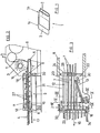
- the folded and possibly trimmed folding products are, as can be seen in FIG. 2, deposited by a paddle wheel 3 in the form of a shingled stream 4 on a delivery belt 5, which consists of carrying belts 7 which are guided around belt rollers 6 and are laterally spaced apart.
- the belt rollers 6 can simply be mounted in the side walls 8 of the folder.
- the delivery belt 5 leading out of the folder forms the first section of a multi-part transport route leading to a further processing device, for example to a packaging device.
- holding devices are provided on both sides of the shingled stream 4, which hold the passing folding products at the respectively assigned free edge 2 and transport them further in the direction of transport and from one another separate, ie pull apart sideways.
- Belt rollers are also provided to accommodate the conveyor belts 7 forming the transport route section 9 and the further transport route sections.
- a common belt roller can be provided in the toothing area of successive transport route sections, on which the carrying belts 7 of successive transport route sections are lined up in an alternating sequence, which automatically results in a drive-related connection of the individual transport route sections.
- At least one upper and one associated lower clamping band 10 and 11 are provided, respectively, web guides 12 and 13, each of which delimit a straight, continuous clamping gap 14, which extends over its entire length and which faces from the respective one , through the relevant edges 2 formed edge strips of the scale web 4 is penetrated.
- the two web guides 12 and 13 can be extended laterally with their front end opposite to the transport direction indicated by the arrow 15.
- the one web guide 12 is arranged parallel to the transport direction and only the other web guide 13 with its front end at a certain angle relative to the transport direction is flared.
- the length of the web guides 12 and 13 and the size of the opening angle are chosen so that a complete separation and a sufficient distance between the separated products are achieved even with the maximum product width.
- the maximum product width corresponds to the working width of the upstream folder minus the width of the smallest required offset. If the product width changes, only the width of the offset is expediently changed, so that no lateral adjustment of the web guides 12 or 13 is necessary.
- the web guides can therefore be arranged stationary. However, it would also be conceivable to provide lateral adjustability. For this it is sufficient if only the web guide 12 parallel to the direction of transport is arranged to be laterally adjustable.
- the clamping bands 10, 11 forming the web guides 12 and 13 are driven by the folder.
- the drive takes place via the conveyor belt 5, which is driven in a manner not shown here.
- the lower clamping belt 10 of the web guide 12 parallel to the transport direction is accommodated on the belt rollers 6 assigned to the adjacent carrying belts 7, of which the belt roller at the rear in the transport direction also belongs to the delivery belt 5 .
- the upper clamping band 11 is received on band wheels 18 arranged above the band rollers 6.
- the drive coupling with the assigned lower clamping band 10 takes place, as can best be seen from FIG. 4, via spur gears 19 arranged on laterally projecting drive stubs 19.
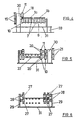
- the clamping bands 10 and 11 of the laterally flared web guide 13 are on in the area between the web rollers 6 Transport route section 9 arranged band wheels 20 which, as shown in FIG. 5, are also drivingly coupled to each other by spur gears 21 placed on laterally projecting drive stubs.
- the torque is introduced via a cardan shaft 22, which is connected to the front belt roller 6 of the delivery belt 5 by means of a countershaft arranged here laterally outside of the web guide 12.
- a toothed belt 23 is provided for this purpose, which is received on a toothed belt pinion 24 on the belt roll side and a toothed belt wheel 25 mounted parallel to the axis thereof.
- the clamping tapes 10 and 11 can be designed as simple tapes similar to the support tapes 7. In order to achieve a smooth running of the clamping bands 10 and 11, they should be designed as toothed belts in the exemplary embodiment shown, which in a simple manner achieves exact synchronism of the clamping bands. This ensures that there is no relative movement of the clamping bands relative to the products detected on the edge, so that they are protected.
- the belt wheels 18 and 20 are designed in this case as toothed belt wheels.
- the belt rollers 6 are provided with the clamping belt 10, which is accommodated thereon and assigned to the web guide 12, toothed belt pinions 26.
- the web guides 12 and 13 can each be formed by aligned individual bands or multiple bands.
- 12 individual belts are provided to form the web guide.
- Double belts are provided to form the web guide 13.
- pressure rollers 27 are provided in the area between the deflection devices assigned to the clamping bands 10 and 11, as can be seen in particular in FIGS. 2 and 6, which support the effective engagement strand of the respectively assigned clamping band, so that over the entire length of the Clamping gap 14 reliable sheet entrainment is guaranteed.
- the pressure rollers 27 assigned to the lower clamping band 10 and the respectively associated upper clamping band 11 are offset with respect to one another in the transport direction, so that a certain elasticity is retained in the region of the clamping gap 14, which thus also copies of stronger material or thickening of the scale flow without damaging the drive means and can record without readjustment, which ensures trouble-free transport.
- the distance between the toothed belt wheels 18 can be adjustable to accomplish any length compensation that may be required. In the exemplary embodiment shown, one or both toothed belt wheels 18 should simply be arranged correspondingly resiliently. When processing shingled streams with a thickness that differs greatly from one another, it may be expedient to arrange at least the upper and / or the lower pressure rollers 27 in an adjustable manner.
- An inlet or outlet gap may result in the area of the belt deflections.
- the pressure rollers 27 are freely rotatably received on side cheeks 28, which in turn are fastened to holders 29 fixed to the housing.
- bearing blocks 30 arranged on a carrier plate 31 are provided.
- the carrier plate 31 is pivotally attached to the folder side walls 8 by means of holders 32 and rests on the floor via supports 33.
- the toothed belt wheel 25 connected to the cardan shaft 22 can simply be found in egg ner projection of the adjacent bearing block 30 may be mounted.
- the holders 29 assigned to the cheeks 28 are also fastened on the carrier plate 31.
- the transport route section 9 adjoining the transport route section 9 having the lateral web guides 12 and 13 is positioned so close with its rear belt roller 6 to the front belt roller 6 of section 9 that there is a smooth transition.
- the side supports 34 of section 17 can be releasably attached to the adjacent bearing blocks 30.
Landscapes
- Engineering & Computer Science (AREA)
- Mechanical Engineering (AREA)
- Delivering By Means Of Belts And Rollers (AREA)
- Folding Of Thin Sheet-Like Materials, Special Discharging Devices, And Others (AREA)
- Separation, Sorting, Adjustment, Or Bending Of Sheets To Be Conveyed (AREA)
Claims (10)
Applications Claiming Priority (2)
| Application Number | Priority Date | Filing Date | Title |
|---|---|---|---|
| DE19823212350 DE3212350C3 (de) | 1982-04-02 | 1982-04-02 | Vorrichtung zum Auseinanderziehen von ineinandersteckenden Bogen. |
| DE3212350 | 1982-04-02 |
Publications (3)
| Publication Number | Publication Date |
|---|---|
| EP0091582A1 EP0091582A1 (fr) | 1983-10-19 |
| EP0091582B1 true EP0091582B1 (fr) | 1986-02-19 |
| EP0091582B2 EP0091582B2 (fr) | 1988-09-21 |
Family
ID=6160110
Family Applications (1)
| Application Number | Title | Priority Date | Filing Date |
|---|---|---|---|
| EP83102911A Expired EP0091582B2 (fr) | 1982-04-02 | 1983-03-24 | Dispositif pour étirer des piles de produits pliés mutuellement déplacées transversalement par rapport à la direction de transport |
Country Status (4)
| Country | Link |
|---|---|
| US (1) | US4477066A (fr) |
| EP (1) | EP0091582B2 (fr) |
| JP (1) | JPS58197145A (fr) |
| DE (2) | DE3212350C3 (fr) |
Cited By (1)
| Publication number | Priority date | Publication date | Assignee | Title |
|---|---|---|---|---|
| DE10059000A1 (de) * | 2000-11-28 | 2002-06-13 | Koenig & Bauer Ag | Verfahren und Vorrichtung zum Querverschieben von Falzprodukten |
Families Citing this family (7)
| Publication number | Priority date | Publication date | Assignee | Title |
|---|---|---|---|---|
| DE3400639A1 (de) * | 1984-01-11 | 1985-07-18 | M.A.N.- Roland Druckmaschinen AG, 6050 Offenbach | Vorrichtung zum auseinanderziehen von quer zur transportrichtung gegeneinander versetzten druckexemplaren |
| AT395302B (de) * | 1989-08-31 | 1992-11-25 | Strohal Gmbh | Vorrichtung zum aufteilen eines schuppenstromes aus jeweils uebereinanderliegenden nutzen |
| US5882006A (en) * | 1995-10-06 | 1999-03-16 | Baldwin Technology Corporation | Apparatus and method for turning and orienting articles within an article pathway |
| US6158735A (en) * | 1998-02-09 | 2000-12-12 | Heidelberger Druckmaschinen Ag | Apparatus and method for splitting a stream of signatures into a first and second substream of signatures |
| DE10038648A1 (de) * | 2000-08-08 | 2002-02-21 | Markus Gampl | Gerät zur Entnahme von Flächengebilden aus einem Schuppenstrom solcher Flächengebilde |
| CH701621A1 (de) * | 2009-08-03 | 2011-02-15 | Ferag Ag | Vorrichtung und Verfahren zum Ablegen von Produkten. |
| CN102442571B (zh) * | 2011-09-26 | 2013-09-11 | 上海汉铁机械有限公司 | 纸板堆码机差速分单装置及其分单方法 |
Family Cites Families (11)
| Publication number | Priority date | Publication date | Assignee | Title |
|---|---|---|---|---|
| FR647597A (fr) * | 1927-02-01 | 1928-11-26 | Telephon Apparat Fabrik | Installation de bandes transporteuses |
| GB1048465A (en) * | 1964-02-21 | 1966-11-16 | Leipziger Buchbinderereimaschi | Improvements in or relating to a device for separating incomplete brochures from thefeeding flow of a gathering and stitching machine |
| CH521911A (de) * | 1970-01-09 | 1972-04-30 | Fehr & Reist Ag | Einrichtung zum Öffnen von gefalteten, gebundenen oder gehefteten, mehrblättrigen Papiererzeugnissen |
| DE2027422C3 (de) * | 1970-06-04 | 1975-07-03 | Willi Kluge | Vorrichtung zum Aufteilen eines Bandes aus schuppenförmkj übereinanderliegenden flachen Gegenständen, insbesondere Zeitungen |
| JPS505700B1 (fr) * | 1970-12-25 | 1975-03-06 | ||
| DE2331473A1 (de) * | 1973-06-20 | 1975-01-09 | Roland Offsetmaschf | Vorrichtung zur foerderung von bogen |
| DE2417614C3 (de) * | 1974-04-10 | 1977-11-03 | Gruner & Jahr | Vorrichtung zum auslegen von produkten an einer rollenrotationsdruckmaschine |
| DE2554662A1 (de) * | 1975-12-05 | 1977-06-23 | Koenig & Bauer Ag | Verfahren und vorrichtung zum unmittelbaren besaeumen in rollenrotationsdruckmaschinen erzeugter, gefalzter signaturen |
| DD126257B1 (de) * | 1976-06-22 | 1981-01-28 | Guenter Thieme | Bandfoerdervorrichtung zum ausgeben und weiterfoerdern von bogen |
| JPS54144665A (en) * | 1978-04-30 | 1979-11-12 | Masaharu Matsuo | Paper feeder |
| DE2917250A1 (de) * | 1979-04-27 | 1980-10-30 | Gruner & Jahr | Vorrichtung zur taktung der ueberlappungslaenge von in einem im wesentlichen gleichmaessigen schuppenstrom gefoerderten, flaechenhaften produkten |
-
1982
- 1982-04-02 DE DE19823212350 patent/DE3212350C3/de not_active Expired
-
1983
- 1983-03-15 US US06/475,577 patent/US4477066A/en not_active Expired - Lifetime
- 1983-03-24 EP EP83102911A patent/EP0091582B2/fr not_active Expired
- 1983-03-24 DE DE8383102911T patent/DE3362147D1/de not_active Expired
- 1983-04-01 JP JP58058570A patent/JPS58197145A/ja active Pending
Cited By (1)
| Publication number | Priority date | Publication date | Assignee | Title |
|---|---|---|---|---|
| DE10059000A1 (de) * | 2000-11-28 | 2002-06-13 | Koenig & Bauer Ag | Verfahren und Vorrichtung zum Querverschieben von Falzprodukten |
Also Published As
| Publication number | Publication date |
|---|---|
| US4477066A (en) | 1984-10-16 |
| DE3212350A1 (de) | 1983-10-13 |
| DE3362147D1 (en) | 1986-03-27 |
| EP0091582A1 (fr) | 1983-10-19 |
| JPS58197145A (ja) | 1983-11-16 |
| DE3212350C2 (de) | 1987-03-26 |
| DE3212350C3 (de) | 1988-10-20 |
| EP0091582B2 (fr) | 1988-09-21 |
Similar Documents
| Publication | Publication Date | Title |
|---|---|---|
| AT397370B (de) | Vorrichtung zum sammeln von gefalzten druckbogen | |
| EP0073388B1 (fr) | Dispositif pour changer le sens de mouvement de lettres et des objets rectangulaires similaires | |
| DE3700959C2 (de) | Bogensammelvorrichtung | |
| EP2199240B1 (fr) | Dispositif destiné à la séparation de pièces | |
| DE2823247C2 (de) | Einrichtung zur Umlenkung eines aus bogenförmigen Produkten bestehenden Produktstroms | |
| DE1761688B2 (de) | Transporteinrichtung für in einer Schuppenformation anfallende, flächenhafte Gebilde | |
| EP0498068A1 (fr) | Plieuse, dans laquelle le transport d'exemplaires pliés est realisé en passant par des moyens de transport, des galets partiels et des cordons | |
| DE2814383C3 (de) | Vorrichtung zum gerichteten Ablegen von einzeln angeförderten biegeweichen Folien o. dgl. | |
| EP2415700A2 (fr) | Dispositif d'orientation d'un produit plat | |
| DE69618520T2 (de) | Umlenkvorrichtung zum Transport von Produkten, insbesondere von graphischen Produkten oder Verlagsprodukten | |
| DE3315490A1 (de) | Verfahren und vorrichtung zum stapeln von druckbogen o.dgl. | |
| DE3108044C2 (de) | Vorrichtung zur Handhabung von Materialbogen | |
| CH687245A5 (de) | Einrichtung zum Foerdern und Trennen von gefalteten Druckprodukten. | |
| DE2917250A1 (de) | Vorrichtung zur taktung der ueberlappungslaenge von in einem im wesentlichen gleichmaessigen schuppenstrom gefoerderten, flaechenhaften produkten | |
| DE3119016C2 (fr) | ||
| DE3212350C3 (de) | Vorrichtung zum Auseinanderziehen von ineinandersteckenden Bogen. | |
| DE102010031668B4 (de) | Falt - Anlage für Wellpappebahnen | |
| DE2848817C2 (de) | Fördereinrichtung zum Fördern von stabförmigen Gegenständen der tabakverarbeitenden Industrie | |
| EP0625121A1 (fr) | Installation pour le transfert d'un flux de nappes constitue de produits imprimes | |
| EP1505026B1 (fr) | Dispositif pour le centrage d'une formation imbriquée | |
| EP0308688B1 (fr) | Dispositif d'alimentation des feuilles autour d'une trajectoire curviligne | |
| EP0078519B1 (fr) | Dispositif pour desserrer une formation en écailles de produits imprimés | |
| DE2903771A1 (de) | Saugbremsvorrichtung | |
| EP0326518B1 (fr) | Dispositif de transport à bandes pour déplacer un courant de produits plats | |
| CH631410A5 (en) | Device for homogenising an imbricated stream formed from flat products, in particular printed products |
Legal Events
| Date | Code | Title | Description |
|---|---|---|---|
| PUAI | Public reference made under article 153(3) epc to a published international application that has entered the european phase |
Free format text: ORIGINAL CODE: 0009012 |
|
| AK | Designated contracting states |
Designated state(s): CH DE FR GB IT LI SE |
|
| 17P | Request for examination filed |
Effective date: 19830825 |
|
| GRAA | (expected) grant |
Free format text: ORIGINAL CODE: 0009210 |
|
| AK | Designated contracting states |
Designated state(s): CH DE FR GB IT LI SE |
|
| REF | Corresponds to: |
Ref document number: 3362147 Country of ref document: DE Date of ref document: 19860327 |
|
| ET | Fr: translation filed | ||
| ITF | It: translation for a ep patent filed | ||
| PLBI | Opposition filed |
Free format text: ORIGINAL CODE: 0009260 |
|
| 26 | Opposition filed |
Opponent name: M.A.N.- ROLAND DRUCKMASCHINEN AKTIENGESELLSCHAFT, Effective date: 19861105 |
|
| PUAH | Patent maintained in amended form |
Free format text: ORIGINAL CODE: 0009272 |
|
| STAA | Information on the status of an ep patent application or granted ep patent |
Free format text: STATUS: PATENT MAINTAINED AS AMENDED |
|
| 27A | Patent maintained in amended form |
Effective date: 19880921 |
|
| AK | Designated contracting states |
Kind code of ref document: B2 Designated state(s): CH DE FR GB IT LI SE |
|
| ET3 | Fr: translation filed ** decision concerning opposition | ||
| ITTA | It: last paid annual fee | ||
| EAL | Se: european patent in force in sweden |
Ref document number: 83102911.1 |
|
| REG | Reference to a national code |
Ref country code: GB Ref legal event code: IF02 |
|
| PGFP | Annual fee paid to national office [announced via postgrant information from national office to epo] |
Ref country code: GB Payment date: 20020227 Year of fee payment: 20 |
|
| PGFP | Annual fee paid to national office [announced via postgrant information from national office to epo] |
Ref country code: FR Payment date: 20020322 Year of fee payment: 20 |
|
| PGFP | Annual fee paid to national office [announced via postgrant information from national office to epo] |
Ref country code: SE Payment date: 20020402 Year of fee payment: 20 |
|
| PGFP | Annual fee paid to national office [announced via postgrant information from national office to epo] |
Ref country code: DE Payment date: 20020403 Year of fee payment: 20 |
|
| PGFP | Annual fee paid to national office [announced via postgrant information from national office to epo] |
Ref country code: CH Payment date: 20020405 Year of fee payment: 20 |
|
| PG25 | Lapsed in a contracting state [announced via postgrant information from national office to epo] |
Ref country code: LI Free format text: LAPSE BECAUSE OF EXPIRATION OF PROTECTION Effective date: 20030323 Ref country code: GB Free format text: LAPSE BECAUSE OF EXPIRATION OF PROTECTION Effective date: 20030323 Ref country code: CH Free format text: LAPSE BECAUSE OF EXPIRATION OF PROTECTION Effective date: 20030323 |
|
| REG | Reference to a national code |
Ref country code: GB Ref legal event code: PE20 |
|
| REG | Reference to a national code |
Ref country code: CH Ref legal event code: PL |
|
| EUG | Se: european patent has lapsed |