EP0091747A2 - Erzeugte Nockenoberflächen für Zwangsläufigen Antrieb - Google Patents
Erzeugte Nockenoberflächen für Zwangsläufigen Antrieb Download PDFInfo
- Publication number
- EP0091747A2 EP0091747A2 EP83301639A EP83301639A EP0091747A2 EP 0091747 A2 EP0091747 A2 EP 0091747A2 EP 83301639 A EP83301639 A EP 83301639A EP 83301639 A EP83301639 A EP 83301639A EP 0091747 A2 EP0091747 A2 EP 0091747A2
- Authority
- EP
- European Patent Office
- Prior art keywords
- cam
- shaft
- axis
- improvement
- rotation
- Prior art date
- Legal status (The legal status is an assumption and is not a legal conclusion. Google has not performed a legal analysis and makes no representation as to the accuracy of the status listed.)
- Granted
Links
Images


Classifications
-
- F—MECHANICAL ENGINEERING; LIGHTING; HEATING; WEAPONS; BLASTING
- F16—ENGINEERING ELEMENTS AND UNITS; GENERAL MEASURES FOR PRODUCING AND MAINTAINING EFFECTIVE FUNCTIONING OF MACHINES OR INSTALLATIONS; THERMAL INSULATION IN GENERAL
- F16H—GEARING
- F16H48/00—Differential gearings
- F16H48/12—Differential gearings without gears having orbital motion
- F16H48/14—Differential gearings without gears having orbital motion with cams
- F16H48/142—Differential gearings without gears having orbital motion with cams consisting of linked clutches using axially movable inter-engaging parts
- F16H48/145—Differential gearings without gears having orbital motion with cams consisting of linked clutches using axially movable inter-engaging parts with friction clutching members
-
- F—MECHANICAL ENGINEERING; LIGHTING; HEATING; WEAPONS; BLASTING
- F16—ENGINEERING ELEMENTS AND UNITS; GENERAL MEASURES FOR PRODUCING AND MAINTAINING EFFECTIVE FUNCTIONING OF MACHINES OR INSTALLATIONS; THERMAL INSULATION IN GENERAL
- F16H—GEARING
- F16H48/00—Differential gearings
- F16H48/12—Differential gearings without gears having orbital motion
- F16H48/14—Differential gearings without gears having orbital motion with cams
-
- F—MECHANICAL ENGINEERING; LIGHTING; HEATING; WEAPONS; BLASTING
- F16—ENGINEERING ELEMENTS AND UNITS; GENERAL MEASURES FOR PRODUCING AND MAINTAINING EFFECTIVE FUNCTIONING OF MACHINES OR INSTALLATIONS; THERMAL INSULATION IN GENERAL
- F16H—GEARING
- F16H48/00—Differential gearings
- F16H48/20—Arrangements for suppressing or influencing the differential action, e.g. locking devices
- F16H48/22—Arrangements for suppressing or influencing the differential action, e.g. locking devices using friction clutches or brakes
-
- Y—GENERAL TAGGING OF NEW TECHNOLOGICAL DEVELOPMENTS; GENERAL TAGGING OF CROSS-SECTIONAL TECHNOLOGIES SPANNING OVER SEVERAL SECTIONS OF THE IPC; TECHNICAL SUBJECTS COVERED BY FORMER USPC CROSS-REFERENCE ART COLLECTIONS [XRACs] AND DIGESTS
- Y10—TECHNICAL SUBJECTS COVERED BY FORMER USPC
- Y10T—TECHNICAL SUBJECTS COVERED BY FORMER US CLASSIFICATION
- Y10T74/00—Machine element or mechanism
- Y10T74/19—Gearing
- Y10T74/19005—Nonplanetary gearing differential type [e.g., gearless differentials]
Definitions
- the present invention relates to positive drives, and more particularly, to an improved clutch actuating mechanism for use in positive drives.
- the improved clutch actuating mechanism of the present invention may be utilized advantageously in many different devices, it is especially advantageous when used in a traction modifying device, and more specifically, in a positive drive, and will be described in connection therewith.
- Traction modifying devices have become popular for use in vehicles, in the drive train between the vehicle engine and the driven wheels.
- the primary function of a traction modifying device is to facilitate driving on slippery surfaces and in off-road conditions. These devices are especially useful where one of the driven wheels is momentarily subjected to worse traction conditions than the other driven wheel.
- Traction modifying devices are generally categorized in three classes:.
- the engine power is transmitted approximately equally to the driven wheels, which rotate at the same speed.
- the engine power is transmitted to the driven wheels in proportion to their instantaneous traction limitations, whereby the wheels are still driven at the same speed.
- a positive drive When the vehicle turns a tight corner, power is transmitted only to the slower moving wheel, while the faster moving wheel is permitted to free wheel, relative to the input.
- the positive drive transmits slightly more torque to the slower turning wheel than to the faster turning wheel.
- a positive drive performs in a manner similar to an open differential during operating conditions which would make an open differential desirable, and performs in a manner similar to a rigid axle when operating conditions would make a rigid axle aesirable.
- a clutch actuating mechanism of the type including an input member adapted to be rotated by input driving torque, and an output member defining an axis of rotation of the mechanism.
- a clutch means is operably associated with the output member and has a disengageo mode and an engaged mode. In the disengaged mode, the clutch means allows the output member to rotate relative to the input member, and in the engaged mode, the clutch means maintains a predetermined rotational relationship between the output member and the input member.
- a cam means is operably associated with the clutch means to move the clutch means from the disengaged mode to the engaged mode.
- a shaft means is disposed adjacent the cam means and is mounted for rotation with the input means.
- Operative movement of the cam means to move the clutch means occurs in response to pivotal movement of the shaft means, about the axis of the mechanism, relative to the cam means.
- the cam means includes a circumferentially-extending ramp cam surface
- the shaft means includes a shaft cam surface disposed to engage the ramp cam surface during the pivotal movement of the shaft means.
- the improvement in the clutch actuating mechanism comprises the ramp cam surface and the shaft cam surface both being defined by a common locus of generating lines, whereby the cam surfaces maintain substantially surface-to-surface contact over the full range of the pivotal movement of the shaft means.
- each of the generating lines is tangential to an imaginary construction cylinder, the axis of which coincides with the axis of rotation of the mechanism.
- Each of the generating lines is disposed at an oblique angle B relative to a first construction plane containing the axis of the shaft means and being perpendicular to the axis of the mechanism.
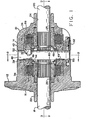
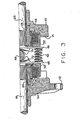
- FIGS. 1-3 show a one piece housing 10 which has a flange 12 that is designed for securement to an input gear.
- a pair of windows 14 (FIG. 2) are located in housing 10 and are sized for insertion of the components of the positive drive within a cavity 16 of housing 10.
- a pair of axles 18 and 20 are rotatable within axially aligned openings 22 ana 24 in the housing.
- Components of the drive include a pair of identical rotatable splined couplings 26 and 28 having internal teeth engaged with teeth on inner ends of axles 18 and 20.
- a pair of identical drive couplings 30 and 32 are journalled in cavity 16 for rotation relative to housing 10.
- Couplings 30 and 32 each include an internal array of teeth 34 and 36, respectively, and spaced, radially disposed cams 38 and 40, best illustrated in FIGS. 4-6.
- Preloaded springs 42 contact at each end a pair of identical spring plates 44 and 46 in contact with couplings 30 and 32 to bias the drive couplings axially outwardly toward axles 18 and 20.
- shaft 48 Interposed between cams 38 and 40 is a shaft 48 having eight cam surfaces 49, four on each end, for engagement with cam surfaces 51 of cams 38 and 40 (see FIGS. 4-6).
- the shaft projects through a pair of aligned openings 50 in housing 10 and is secured to the housing by a fastener 52.
- shaft 48 may have a cross section that is not circular, e.g., the cross section may be a square, a hexagon, or of variable cross section as long as it may be placed within its given location.
- Drive clutches 54 and 56 each include annular discs, a drive coupling, and a spline coupling.
- Discs 58 of clutch 54 have teeth engaged with teeth 34 of drive coupling 30 and discs 60 of clutch 54 are interposed between each of the discs 58 and have teeth engaged with an external array of teeth 62 on spline coupling 26.
- the toothed engagement of the discs ensure one-to-one rotation of each of the discs with the respective coupling.
- An annular thrust washer 64 is interposed between the disc 60 farthest to the left in FIG. 1 and housing 10. The disc 60 farthest to the right in FIG. 1 contacts a radially extending annular surface of drive coupling 30.
- Clutch 56 is configured similar to clutch 54 with discs 66 and 68 and thrust washer 70.
- the annular discs 58, 60, 66, and 68 are well known in the traction modifying differential art as illustrated by U.S. Pat. No. 3,313,180 and may be secured to the respective coupling by means other than teeth to accomplish the one-to-one rotation.
- Spring plates 44 and 46 include a pair of spaced wings 72 and 74 which encircle shaft 48 and form a support for balking clamps 76.
- the balking clamps each include an opening 78 to loosely receive shaft 48.
- Axles 18 and 20 are secured to the drive by means of a pair of "C" clips 80 in a well known manner.
- a thrust washer 82 is seated between the end of each of the couplings 26 and 28 and the housing 10.
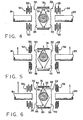
- FIGS. 4-6 The operation of the positive drive is best described with reference to FIGS. 4-6.
- the positive drive may be used in either front wheel or rear wheel drive vehicles or between two drive axles. It will be described with reference to a rear drive automotive application.
- FIG. 4 shows the vehicle in a stationary position with axles 18 and 20 adapted to be connected to ground engaging wheels.
- Shaft 48 is secured to housing 10 which is rotated by an input gear supplied with power from the engine of the automobile. Rotation of couplings 30 and 32 without springs 42 will be resisted to some degree by the friction between the discs. The degree of resistance is increased by the preloaded force exerted by springs 42.
- axle 18 When the automobile is turning a corner, one axle will want to rotate faster than the other axle. Cornering initially causes a condition to exist similar to that illustrated in FIG. 5. However, as one axle, e.g., 18, begins to rotate faster than the other axle 20 as shown by the magnitude of the arrows in FIG. 6, drive coupling 30 is rotated by axle 18 via clutch 54 in the direction of axle 18 causing cam 38 to move out of drive engagement with surfaces on shaft 48. This results in cisconnecting axle 18 from coupling 30 (except for a small amount of preload torque transmitted through the disc due to spring 42) and allowing axle 18 to rotate at any desired angular velocity faster than the angular velocity of axle 20. Axle 20, the slower rotating axle, will continue to be driven by shaft 48 through cam 40 and clutch 56.
- balking clamps 76 Without balking clamps 76, continued rotation of coupling 30 in the direction of rotation of axle 18 would again result in contact between cam 38 and surfaces on shaft 48 on the opposite drive cam and hence axial movement of coupling 30 and the driving of axle 18 at the angular velocity of axle 20. Such continued rotation in a positive drive is prevented by limiting the rotational movement between couplings 30 and 32 relative to one another. As illustrated in FIG. 6, if coupling 30 continues to rotate in the same direction as axle 18 at an angular velocity exceeding that of coupling 32, contact is made between surface 84 of cam 38 and surface 86 of balking clamp 76. Balking clamp 76 is so configured to also ensure contact between surface 88 of cam 40 and surface 90 of balking clamp 76.
- balking clamp 76 Due to the limited amount of axial movement that exists between couplings 30 and 32, and the relative rotation between couplings 30 and 32, and the tolerances within the clutches, the distances between surfaces 84 and 88 on cams 38 and 40, and the distance between surfaces 86 and 90 on balking clamps 76 must be carefully controlled. Due to the simplicity of design of the balking clamp 76 and the cams 38 and 40, this may be readily and inexpensively accomplished. The unit will also operate in a similar manner in left turns and when driven in reverse, and such operation will not be described in detail herein.
- FIGS. 7A, 7B, and 7C are views taken in a direction approximately normal to one of the ramp cam surfaces 51, illustrating the positional relationship of the shaft cam surface 49 to the ramp cam surface 51.
- FIGS. 7A, 7B, and 7C include an indication of the pivotal movement of the shaft 48 and illustrates various operating positions.
- FIG. 7A illustrates the condition as the shaft 48 approaches the position shown in FIG. 5, and cam surface 49 begins engagement with cam surface 51.
- the shaft 48 would be pivoted about 1.5 degrees about the axis defined by the axles 18 and 20.
- FIG. 7B it may be seen that shaft 48 is pivoted about 3.0 degrees, thus moving shaft cam surface 49 into engagement with a different portion of the ramp cam surface 51.
- FIG. 7B represents a condition which would occur in the event of loose tolerances, thin clutch discs, or as a result of a period of wear during operation.
- FIG. 7C the shaft 48 is pivoted to a position 4.5 degrees from its original, centered position shown in FIG. 4.
- FIG. 7C represents a condition in which factors such as relatively looser tolerances have been followed by wear of components such as clutch discs, thus permitting a greater range of pivotal movement of the shaft 48, in order to fully engage the respective clutch 54.
- the range of pivotal movement of shaft 48, as represented in FIGS. 7A, 7B, and 7C is by way of example only, and in various designs, and under various operating conditions, the range of movement of surface 49, relative to surface 51, may differ.
- both of the surfaces 49 and 51 are somewhat "warped", i.e., if the portion of the cam surface 51 near the axis 92 were considered generally parallel to the plane of the drawing, then at the right-hand end of the surface 51, the radially outermost portion of surface 51 would be below the plane of the drawing, while the radially innermost portion of the surface 51 would be above the plane of the drawing.
- This explanation is not intended as an accurate description of the surface, and is not intended to limit the invention, but is intended merely as an aid in understanding the subsequent explanation.
- the distance of movement in the circumferential direction of area 95 will be greater than the distance of movement in the circumferential direction of area 96, because of the different radial locations. Therefore, in order for both of the areas 95 and 96 to see the same amount of cam rise, and maintain surface contact, it is necessary for the angle of the cam surface 51 to be shallower further outward radially (or to be steeper toward the radially innermost part of surface 51). As a result of this decrease in the cam angle toward the radially outermost part of the cam surface 51, the cam surface 51 has the warped configuration generally described previously.
- the invention provides a shaft cam surface 49 and a ramp cam surface 51 which are in engagement, or surface-to-surface contact, throughout the range of pivotal movement of the shaft 48. Because of this particular objective, it is one feature of the present invention that the surfaces 49 and 51 are both defined by the same locus of generating lines, from which it follows that full surface-to-surface contact will occur throughout the operating range. It is another feature of the present invention to provide a simple, practical method for generating tne engaging surfaces 49 and 51, whereby the desired surface-to-surface contact occurs.
- Applicant believes that it would be possible, by the use of integral equations, to calculate the theoretical configuration of surfaces 49 and 51 which would mathematically result in perfect surface contact throughout the operating range which would be a long and somewhat complex equation, not compatible to known fabrication methods.
- An important aspect of the present invention is to provide a practical method of generating the surfaces such that the generated surface will, over its entire extent, be within about .0001 inches of the theoretical surface. It should also be noted that the method of generation to be described and illustratea hereinafter is the same for all eight of the shaft cam surfaces 49 and for all eight of the ramp cam surfaces 51, and therefore, description of the generation of one of the surfaces 49, and one of the surfaces 51 will be considered sufficient enablement of the invention.
- each of the cam surfaces is defined by a locus of lines perpendicular to the axis of the differential, as is generally well known in the art.
- the generating method of the present invention utilizes an imaginary construction cylinder 94, the axis of which coincides with the axis of rotation of the positive drive, i.e., the axis of rotation of the axles 18 and 20.
- a cylinder as the construction form is not an essential feature of the invention, it will be understooa from the subsequent description of the method of generation that the cylinder 94 more or less inherently occurs.
- the cam surface 49 appears somewhat narrower than in the normal view of FIG. 7, because in FIGS.
- the view of surface 49 is at an oblique angle.
- the construction cylinder 94 has a radius A, and in the subject embodiment, the radius A is about 7U percent of the radius of the shaft 48, by of example only. It is believed that in most designs, the radius A will not exceed the radius of the shaft 48.
- each of the surfaces 49 and 51 is defined by a common locus of generating lines.
- generating lines 101, 102, and 103 are illustrated, it being understood that only three generating lines are shown for simplicity, and that mathematically, the actual number of generating lines would approach infinity.
- Each of the generating lines is tangential to the construction cylinder 94, and each generating line is oriented at an oblique angle B relative to a construction plane containing the axis 92 of the shaft and being perpendicular to the axis of the drive (see FIG. 8B).
- the generating lines it is possible to view the generating lines as pivoting about a stationary cylinder 94, or alternatively, to view the cylinder 94 as being rotatable, with all of the generating lines being attached to tangential to) the cylinder 94 at a single line, parallel to the axis of cylinder 94.
- the distance C is measured in a direc- .
- the distance C is preferably expressed as a distance per degree of rotation of the cylinder 94, and corresponds to the cam rise which is specified for the cam members of the prior art locking differentials.
- the cam rise i.e., axial movement of the cam per degree of relative rotation between the cam members
- the cam rise is determined by the configuration of the clutch. Therefore, once the clutch has been designed, the cam rise needed to engage the clutch can then be determined, after which the cam rise may be considered a fixed input factor when designing the cam mechanism.
- generating line 103 is parallel to the axis 92, as viewea in FIG. 8A.
- This parallel generating line 103 is tangent to the construction cylinder 94 at a point which is separated from the previously referenced construction plane (containing the axis 92) by a distance D.
- the distance D is important because it, in combination with the parallel orientation of the generating line 103 provides a convenient reference, as will be described in greater detail subsequently.
- the shaft cam surface 49 and ramp cam surface 51 are both defined by the locus of all of the generating lines which satisfy the four previously mentioned dimensional factors A, B, C, and D.
- FIGS. 9A and 9B there is illustrated the generation of the ramp cam surface 51 in accordance with the present invention.
- the construction method illustrated in FIGS. 9A and 9B is identical to that illustrated in FIGS. 8A and 8B for generation of the shaft cam surface 49. Therefore, the description of the method illustrated in FIGS. 9A and 9B will not be repeated, but several comments will be offered.
- FIGS. 9A and 9B it should first be noted in FIGS. 9A and 9B that, in adaition to generating lines 101, 102, and 103, additional generating lines 104, 105, and 106 are illustrated, primarily because of the greater circumferential extent of the cam surface 51, compared to the cam surface 49.
- the additional generating lines must still satisfy the requirements set forth previously, e.g., for a given amount of rotation of the construction cylinder 94, the point of tangency of the generating line moves the distance C.
- the distance D to the point of tangency of the generating line 103 (the "reference" generating line) is still measured from the axis 92 of the shaft 48, with only the axis 92 and not the shaft 48 being shown in FIG. 9B.
- each of the generating lines 101-106 represents a machining line, i.e., a line along which machining occurs in order to generate the cam surfaces 49 and 51 having the desired configuration. It is believed to be within the knowledge of those skilled in the machining art to translate the generation method illustrated and described herein into any one of a number of well known machining techniques. However, the particular machining technique used forms no part of the present invention, and will not be described in greater detail herein.
Landscapes
- Engineering & Computer Science (AREA)
- General Engineering & Computer Science (AREA)
- Mechanical Engineering (AREA)
- Retarders (AREA)
- Mechanical Operated Clutches (AREA)
Applications Claiming Priority (2)
| Application Number | Priority Date | Filing Date | Title |
|---|---|---|---|
| US366611 | 1982-04-08 | ||
| US06/366,611 US4513633A (en) | 1982-04-08 | 1982-04-08 | Positive drive and generated cam surfaces therefor |
Publications (3)
| Publication Number | Publication Date |
|---|---|
| EP0091747A2 true EP0091747A2 (de) | 1983-10-19 |
| EP0091747A3 EP0091747A3 (en) | 1984-10-03 |
| EP0091747B1 EP0091747B1 (de) | 1988-05-04 |
Family
ID=23443740
Family Applications (1)
| Application Number | Title | Priority Date | Filing Date |
|---|---|---|---|
| EP83301639A Expired EP0091747B1 (de) | 1982-04-08 | 1983-03-24 | Erzeugte Nockenoberflächen für Zwangsläufigen Antrieb |
Country Status (7)
| Country | Link |
|---|---|
| US (1) | US4513633A (de) |
| EP (1) | EP0091747B1 (de) |
| JP (1) | JPS58184322A (de) |
| AU (1) | AU563535B2 (de) |
| BR (1) | BR8301869A (de) |
| CA (1) | CA1200406A (de) |
| DE (1) | DE3376496D1 (de) |
Cited By (8)
| Publication number | Priority date | Publication date | Assignee | Title |
|---|---|---|---|---|
| WO2001021983A1 (en) * | 1999-09-18 | 2001-03-29 | Ap Hydraulics Limited | Differential mechanisms |
| WO2011012968A1 (en) * | 2009-07-27 | 2011-02-03 | Eaton Corporation | Locking differential having improved torque capacity |
| US8231493B2 (en) | 2009-07-27 | 2012-07-31 | Eaton Corporation | Differential having improved torque capacity and torque density |
| US9151376B2 (en) | 2012-08-29 | 2015-10-06 | Eaton Corporation | Locking differential having dampening communication spring |
| US9303748B2 (en) | 2012-11-19 | 2016-04-05 | Eaton Corporation | Collapsible clutching differential |
| US9309957B2 (en) | 2012-08-29 | 2016-04-12 | Eaton Corporation | Locking differential having combination preload springs for maintained contact |
| US9334941B2 (en) | 2013-03-14 | 2016-05-10 | Eaton Corporation | Inboard spring arrangement for a clutch actuated differential |
| US9453569B2 (en) | 2012-11-28 | 2016-09-27 | Eaton Corporation | Locking differential having preload spring wear pads |
Families Citing this family (20)
| Publication number | Priority date | Publication date | Assignee | Title |
|---|---|---|---|---|
| US4598609A (en) * | 1984-04-23 | 1986-07-08 | Eaton Corporation | Positive drive |
| US4569250A (en) * | 1984-04-23 | 1986-02-11 | Eaton Corporation | Positive drive with torque responsive dampener |
| JPS60182238U (ja) * | 1984-05-15 | 1985-12-03 | 栃木富士産業株式会社 | 動力伝達装置 |
| JPS60182240U (ja) * | 1984-05-15 | 1985-12-03 | 栃木富士産業株式会社 | 動力伝達装置 |
| JPS60182239U (ja) * | 1984-05-15 | 1985-12-03 | 栃木富士産業株式会社 | 動力伝達装置 |
| US4630506A (en) * | 1984-12-06 | 1986-12-23 | Dana Corporation | Drive axle and method of assembling same |
| US4782720A (en) * | 1985-11-12 | 1988-11-08 | Tochigifujisangyo Kabushikigaisha | Power transmission unit |
| US4735108A (en) * | 1985-11-21 | 1988-04-05 | Tochigifujisangyo Kabushikigaisha | Power transmission device |
| US4845831A (en) * | 1985-12-13 | 1989-07-11 | Schou Carl Einar | Open casing, self-locking differential |
| JPH0525946Y2 (de) * | 1987-01-13 | 1993-06-30 | ||
| DE3900818C1 (de) * | 1989-01-13 | 1990-05-10 | Heidelberger Druckmaschinen Ag, 6900 Heidelberg, De | |
| US5590572A (en) * | 1995-07-28 | 1997-01-07 | Titan Wheel International, Inc. | Locking differential including access windows for C-clip retainers |
| US5671640A (en) * | 1996-04-30 | 1997-09-30 | Tractech Inc. | Locking differential with pre-load means and C-clip retainers |
| US5727430A (en) * | 1996-10-24 | 1998-03-17 | Dyneer Corporation | Locking differential including friction pack clutch means |
| US7013987B2 (en) * | 2000-09-08 | 2006-03-21 | Black & Decker | Clutch assembly and clamp mechanism for rotary tool disc |
| US6688194B2 (en) * | 2001-10-04 | 2004-02-10 | Tractech Inc. | Locking differential including improved clutch member and adapter sleeve |
| US7810601B2 (en) * | 2005-10-14 | 2010-10-12 | Team Industries, Inc. | All terrain or utility vehicle having selectable drive configurations and method therefore |
| US7278945B2 (en) * | 2005-10-14 | 2007-10-09 | Team Industries, Inc. | Differential |
| US20080060474A1 (en) * | 2006-09-07 | 2008-03-13 | Katsumoto Mizukawa | Gearless Differential in an Integrated Hydrostatic Transmission |
| US7874954B2 (en) * | 2007-02-14 | 2011-01-25 | Eaton Corporation | Locking differential including resilient disc means |
Family Cites Families (18)
| Publication number | Priority date | Publication date | Assignee | Title |
|---|---|---|---|---|
| US1111728A (en) * | 1913-03-19 | 1914-09-29 | William A Besserdich | Locking device for differential gears. |
| US1477311A (en) * | 1922-12-05 | 1923-12-11 | Horace A Cartwright | Differential mechanism |
| FR769239A (fr) * | 1933-05-17 | 1934-08-22 | Dispositif permettant de remplacer le différentiel dans les voitures automobiles et autres applications | |
| US2060558A (en) * | 1935-01-04 | 1936-11-10 | Lavaud Dimitri Sensaud De | Disk differential gear |
| US2179923A (en) * | 1937-05-27 | 1939-11-14 | Lavaud Dimitri Sensaud De | Disk differential |
| US2397673A (en) * | 1943-03-04 | 1946-04-02 | Frank M Lewis | Dual wheel drive mechanism |
| US2509560A (en) * | 1946-10-02 | 1950-05-30 | Frank M Lewis | Differential mechanism |
| US2555044A (en) * | 1948-09-01 | 1951-05-29 | Frank M Lewis | Differential mechanism |
| US2790334A (en) * | 1953-10-12 | 1957-04-30 | Wildhaber Ernest | Gearless differential |
| US2918831A (en) * | 1957-07-15 | 1959-12-29 | Wildhaber Ernest | Bevel-gear differential |
| US2978929A (en) * | 1959-01-12 | 1961-04-11 | Arthur M Smith | Locking differential |
| US3624717A (en) * | 1970-02-06 | 1971-11-30 | Eaton Yale & Towne | Axle shaft retention system |
| US3611833A (en) * | 1970-02-26 | 1971-10-12 | Eaton Yale & Towne | Differential |
| JPS5135976B1 (de) * | 1971-07-20 | 1976-10-06 | ||
| US3906812A (en) * | 1973-03-31 | 1975-09-23 | Aisin Seiki | Locking differential |
| US4104931A (en) * | 1976-03-19 | 1978-08-08 | Tomich Michael G | Positive hold differential |
| US4136582A (en) * | 1976-04-21 | 1979-01-30 | Fairfield Manufacturing Co., Inc. | Shaft and bore combination |
| US4290321A (en) * | 1979-06-25 | 1981-09-22 | Wilson Denney R | Variable lock differential |
-
1982
- 1982-04-08 US US06/366,611 patent/US4513633A/en not_active Expired - Lifetime
-
1983
- 1983-03-23 CA CA000424222A patent/CA1200406A/en not_active Expired
- 1983-03-24 DE DE8383301639T patent/DE3376496D1/de not_active Expired
- 1983-03-24 EP EP83301639A patent/EP0091747B1/de not_active Expired
- 1983-04-06 AU AU13192/83A patent/AU563535B2/en not_active Ceased
- 1983-04-08 BR BR8301869A patent/BR8301869A/pt not_active IP Right Cessation
- 1983-04-08 JP JP58061045A patent/JPS58184322A/ja active Granted
Cited By (11)
| Publication number | Priority date | Publication date | Assignee | Title |
|---|---|---|---|---|
| WO2001021983A1 (en) * | 1999-09-18 | 2001-03-29 | Ap Hydraulics Limited | Differential mechanisms |
| GB2358682A (en) * | 1999-09-18 | 2001-08-01 | Ap Hydraulics Ltd | Differential mechanisms |
| WO2011012968A1 (en) * | 2009-07-27 | 2011-02-03 | Eaton Corporation | Locking differential having improved torque capacity |
| US8146458B2 (en) | 2009-07-27 | 2012-04-03 | Eaton Corporation | Locking differential having improved torque capacity |
| US8231493B2 (en) | 2009-07-27 | 2012-07-31 | Eaton Corporation | Differential having improved torque capacity and torque density |
| US9151376B2 (en) | 2012-08-29 | 2015-10-06 | Eaton Corporation | Locking differential having dampening communication spring |
| US9309957B2 (en) | 2012-08-29 | 2016-04-12 | Eaton Corporation | Locking differential having combination preload springs for maintained contact |
| US9303748B2 (en) | 2012-11-19 | 2016-04-05 | Eaton Corporation | Collapsible clutching differential |
| US9453569B2 (en) | 2012-11-28 | 2016-09-27 | Eaton Corporation | Locking differential having preload spring wear pads |
| US9334941B2 (en) | 2013-03-14 | 2016-05-10 | Eaton Corporation | Inboard spring arrangement for a clutch actuated differential |
| US9625025B2 (en) | 2013-03-14 | 2017-04-18 | Eaton Corporation | Inboard spring arrangement for a clutch actuated differential |
Also Published As
| Publication number | Publication date |
|---|---|
| EP0091747A3 (en) | 1984-10-03 |
| JPH0420096B2 (de) | 1992-03-31 |
| CA1200406A (en) | 1986-02-11 |
| JPS58184322A (ja) | 1983-10-27 |
| AU563535B2 (en) | 1987-07-16 |
| AU1319283A (en) | 1983-10-13 |
| BR8301869A (pt) | 1983-12-20 |
| US4513633A (en) | 1985-04-30 |
| DE3376496D1 (en) | 1988-06-09 |
| EP0091747B1 (de) | 1988-05-04 |
Similar Documents
| Publication | Publication Date | Title |
|---|---|---|
| US4513633A (en) | Positive drive and generated cam surfaces therefor | |
| US4400996A (en) | Positive clutch differential | |
| US4526063A (en) | Three mode differential | |
| US2971404A (en) | Locking differential | |
| EP0239763B1 (de) | Positiver Antrieb einer Einzelwelle | |
| EP0066449A1 (de) | Nockenvorrichtung für selbstsperrendes oder mit begrenztem Schlupf versehenes Differentialgetriebe | |
| GB2119040A (en) | Self-locking differential | |
| JP2003184993A (ja) | ディファレンシャル・アセンブリにおけるクラッチ・アクチュエータ用のギヤ・モジュール | |
| US5139467A (en) | Spring retainer for limited slip differentials | |
| US4848506A (en) | Drive power transmission device | |
| WO1999022954A2 (en) | Quiet and smooth, positive acting, no-slip differential | |
| US6168545B1 (en) | Limited slip differential with spring-loaded clutches | |
| US4914980A (en) | Limited slip differential assembly | |
| US5616096A (en) | Differential gear unit | |
| US4569250A (en) | Positive drive with torque responsive dampener | |
| US4488454A (en) | Balking clamp positive drive | |
| US3326064A (en) | Differential transmission unit having a resiliently preloaded clutch therein | |
| US4598609A (en) | Positive drive | |
| US6237735B1 (en) | Viscous actuated ball ramp clutch having one-way clutch | |
| US4640143A (en) | Self-locking differential with hexagonal drive rod | |
| JPS6141038A (ja) | 自動車用差動装置 | |
| EP0393285B1 (de) | Kupplung für Kraftübertragung | |
| KR20000022907A (ko) | 점성 진작 볼 램프 클러치 및 그 개선형 하우징 | |
| JPH04262150A (ja) | 特に自動車用の差動器及び継手を備えた変速装置 | |
| EP0263578A1 (de) | Differentialgetriebe mit begrenzter Hemmung |
Legal Events
| Date | Code | Title | Description |
|---|---|---|---|
| PUAI | Public reference made under article 153(3) epc to a published international application that has entered the european phase |
Free format text: ORIGINAL CODE: 0009012 |
|
| AK | Designated contracting states |
Designated state(s): DE FR GB IT |
|
| PUAL | Search report despatched |
Free format text: ORIGINAL CODE: 0009013 |
|
| AK | Designated contracting states |
Designated state(s): DE FR GB IT |
|
| 17P | Request for examination filed |
Effective date: 19850215 |
|
| 17Q | First examination report despatched |
Effective date: 19860326 |
|
| GRAA | (expected) grant |
Free format text: ORIGINAL CODE: 0009210 |
|
| AK | Designated contracting states |
Kind code of ref document: B1 Designated state(s): DE FR GB IT |
|
| ITF | It: translation for a ep patent filed | ||
| REF | Corresponds to: |
Ref document number: 3376496 Country of ref document: DE Date of ref document: 19880609 |
|
| ET | Fr: translation filed | ||
| PLBE | No opposition filed within time limit |
Free format text: ORIGINAL CODE: 0009261 |
|
| STAA | Information on the status of an ep patent application or granted ep patent |
Free format text: STATUS: NO OPPOSITION FILED WITHIN TIME LIMIT |
|
| 26N | No opposition filed | ||
| PGFP | Annual fee paid to national office [announced via postgrant information from national office to epo] |
Ref country code: FR Payment date: 19891210 Year of fee payment: 8 |
|
| PGFP | Annual fee paid to national office [announced via postgrant information from national office to epo] |
Ref country code: GB Payment date: 19910215 Year of fee payment: 9 |
|
| PGFP | Annual fee paid to national office [announced via postgrant information from national office to epo] |
Ref country code: DE Payment date: 19910327 Year of fee payment: 9 |
|
| ITTA | It: last paid annual fee | ||
| PG25 | Lapsed in a contracting state [announced via postgrant information from national office to epo] |
Ref country code: FR Effective date: 19911129 |
|
| REG | Reference to a national code |
Ref country code: FR Ref legal event code: ST |
|
| PG25 | Lapsed in a contracting state [announced via postgrant information from national office to epo] |
Ref country code: GB Effective date: 19920324 |
|
| GBPC | Gb: european patent ceased through non-payment of renewal fee | ||
| PG25 | Lapsed in a contracting state [announced via postgrant information from national office to epo] |
Ref country code: DE Effective date: 19921201 |