EP0091849A2 - Verfahren zum Lesen eines durch einen Nadeldruckkopf gedruckten Textes und Lesekopf zur Durchführung des Verfahrens - Google Patents
Verfahren zum Lesen eines durch einen Nadeldruckkopf gedruckten Textes und Lesekopf zur Durchführung des Verfahrens Download PDFInfo
- Publication number
- EP0091849A2 EP0091849A2 EP83400627A EP83400627A EP0091849A2 EP 0091849 A2 EP0091849 A2 EP 0091849A2 EP 83400627 A EP83400627 A EP 83400627A EP 83400627 A EP83400627 A EP 83400627A EP 0091849 A2 EP0091849 A2 EP 0091849A2
- Authority
- EP
- European Patent Office
- Prior art keywords
- states
- signal
- block
- line
- exploration
- Prior art date
- Legal status (The legal status is an assumption and is not a legal conclusion. Google has not performed a legal analysis and makes no representation as to the accuracy of the status listed.)
- Granted
Links
Images

Classifications
-
- G—PHYSICS
- G06—COMPUTING OR CALCULATING; COUNTING
- G06V—IMAGE OR VIDEO RECOGNITION OR UNDERSTANDING
- G06V10/00—Arrangements for image or video recognition or understanding
- G06V10/10—Image acquisition
-
- G—PHYSICS
- G06—COMPUTING OR CALCULATING; COUNTING
- G06V—IMAGE OR VIDEO RECOGNITION OR UNDERSTANDING
- G06V10/00—Arrangements for image or video recognition or understanding
- G06V10/10—Image acquisition
- G06V10/12—Details of acquisition arrangements; Constructional details thereof
Definitions
- the invention relates to a method for reading printed text by means of a mosaic head, in which an area of the printing line is scanned by an electro-optical process in two crossed scans, longitudinal and transverse, with frequencies in rational relationships, and we develop from this exploration a digital signal that reproduces the signal that commanded printing.
- the invention also relates to a read head for implementing the method.
- the most common electromechanical version of mosaic printheads is the needle head, the operation of which is typical of the mosaic printing process.
- needle print heads which are the electromechanical print devices that currently allow the highest print speeds, have a plurality of adjacent cylindrical needles arranged with their axes aligned transversely to the line, the head moving at substantially uniform speed in the direction of the line; the impression is produced by the projection of certain needles, which press a transfer strip against the support sheet.
- each needle corresponds to a point location, the whole of which for multiplicity constitutes a body of character.
- the protrusion of several needles causes the impression of the corresponding points, the arrangement of which defines the structure of the body.
- the protrusion of the needles for printing a body is carried out in response to a control signal segment, comprising a plurality of binary moments whose succession corresponds to the structure of the body.
- the succession of the bodies is carried out with an axial spacing adjusted to a location diameter.
- each character is formed by a number of joined bodies, often a plurality of bodies, the first and last of which are empty to form the intervals between characters.
- coded prints can be provided, of the kind described in French patent application No. 79 16527 of June 27, 1979, where each body represents a character in ASC1.1 code. with additional rhythm and parity information.
- This coded printing is provided in the margin of an alphanumeric printing to double in concentrated form the plain text, and allow the reading of this text in a directly usable form.
- the alphanumeric printing is controlled from a signal coded in segments at plurality of moments, through transcoding matrices such that a signal segment corresponds to the number of bodies in which the character is inscribed. alphanumeric. Also the reading of an alphanumeric text does not differ essentially from that of a coded text, an exploration body by body in the surface occupied by a character giving rise to a signal in one-to-one correspondence with the command signal d 'impression.
- the process that seems immediate to read a text composed of a succession of bodies of characters, each body consisting of a plurality of locations of circular dots whose arrangement of printed dots corresponds to a determined structure consists in: explore in succession the locations of a body, to recognize which locations are occupied by a printed point, and the bodies of the line, by determining the different reflectance of the printed or blank locations, the resolution of the exploration being that of l 'impression.
- the subject of the invention is a method of reading printed texts by means of a needle head, which supports and compensates for registry errors.
- the invention also relates to such a reading method which takes into account the different printing errors separately, to compensate for them separately.
- the invention proposes a method of reading printed text by means of a mosaic head defining along a line a succession of bodies of characters, each body consisting of a plurality of locations of circular points aligned in across the line, the arrangement of the printed points of a body defining its structure, in which an area of line is explored by an electro-optical process in two crossed scans, longitudinal and transverse, with frequencies in rational relation, and on the basis of this exploration, a signal is made up of segments with a plurality of moments corresponding respectively to the bodies and locations so as to reproduce the signal which commanded the printing, characterized in that at least the first printed line body having a fixed key structure, we explore the line area by elementary grains with a center distance of one step, the transverse scanning being carried out at a clock rate in one period on a column comprising a multiplicity of grains while the longitudinal scanning is carried out at the rhythm of the periods, the column length exceeding that of a body of upper and lower register margins, and the number of steps over a location diameter defining a
- the logical shaping is done by applying the raw exploration signal to a comparator with a threshold adjusted with respect to the maximum amplitude of the raw signal.
- a whole grain factor is determined, and the size of the groups of states referred to the cells is adjusted accordingly.
- the whole grain factor can be calculated by dividing the number of states "1" of the block by the number of moments "1" of the key structure, and the quotient is rounded to the nearest integer.
- the states "1" are counted and the states "0" are counted down, and a moment corresponding to a printed point or not is emitted depending on the account / settlement result is positive or not.
- the invention provides a read head for implementing the method defined above, mounted on a frame so as to be movable in front of a printed text support in the general direction of the lines while after reading a line the support is moved to bring the next line next to the head, the succession of organ movements corresponding to the movements carried out at printing by a needle head, characterized in that it comprises a network aligned with adjacent photodiodes, optical elements such as an image of a strip of text support, transverse to the line, are formed on the network by covering a multiplicity of photodiodes, means for lighting the text support with a substantially uniform illumination of the strip, and means of sequential exploration of the network, controlled by a clock, a network exploration cycle defining the period of the exploration signal, and in that the movement of the read head is controlled at the rate of the periods with a step equal to the bandwidth.
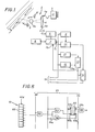
- a reading head 2 as a whole is scrolled along a line, in the direction and direction of the arrow la which comprises an objective 2a, light-emitting diodes 3 and 3 ′ to illuminate the support 1, and an array of photodiodes 4, comprising an alignment of 64 photodiodes.
- the objective 2a projects the image of an elongated strip, transverse to the line la, on the network 4.
- the network 4 is provided with exploration means such that, at the rate of the pulses of a clock 5, applied to a clock input 4a of the network 4, appears on the output 4b a signal representative of the state of each photodiode, in cyclic succession.
- This signal is applied to a logic shaping stage 6, which will be described in more detail with reference to FIG. 3, so that the signal corresponding to the exploration of a photodiode which receives the image of an area printed is at a logical level 1, while that which corresponds to the exploration of a photodiode which receives the image of an unprinted zone is at a logical level 0.
- the speed of advance of the head following the arrow la is correlated with the clock period 5 of such so that two successive explorations of the network 4 correspond to two contiguous bands on the support 1.
- the area whose image covers a photodiode of the network 4 is an image grain.
- the strip 20 corresponds to an exploration, at 64 grains, of a character body with 9 locations 21 to 29, the structure of which is formed by the alternation of printed dots and empty locations , ie 5 points with odd reference and 4 empty locations with even reference. Empty locations have been shown circled for ease of understanding, but in practice these locations are virtual.
- the first 11 grains, 20 M constitute the upper register margin, and the last 8 grains 20 constitute the lower register margin.
- At each location correspond 5 grains, 12-16, 22-26, 32-36, 42-46 and 52-56 for the grains located on printed areas, points 21, 23, 25, 27, 29; 17-21, 27-31, 37-41, and 47-51 for grains located on unprinted areas.
- the exploration signal forms a block with 64 states, the states of rank 1-11, 17-21, 27-31, 37-41, 47-51 and 57-64 are "0" states.
- the circuit 6 includes two extreme value detectors each consisting of a differential amplifier 31 and 32, a bridge of two diodes 33, 34 and an integration capacitor 35, 36.
- the capacitor 35 is charged at the maximum level of exploration voltage applied to terminal 30 corresponding to the printed grains, while the capacitor 36 charges the minimum voltage corresponding to the empty grains.
- the exploration voltage is also applied to the direct input of a differential amplifier 37, mounted as a threshold comparator, the inverting input of which receives an average voltage from the charge voltages of the capacitors 35 and 36.
- the signal formed in circuit 6 is analyzed to determine the upper register margin in circuit 7 coupled to a memory 8.
- a body with a key structure is provided (printed in a side margin where reading begins, and which can be the first body of a coded recording as described in French patent application 79 16525, published under the number 2 459 725).
- the key structure necessarily begins with a printed point 21 below the upper register margin 20 M, and is preferably that shown in FIG. 2, which is expressed as a signal at nine times 101010101.
- the blocks received from circuit 6 are retransmitted on output 7a of the circuit from the first state "1", to attack in particular circuits 11 and 12, which control the sorting of signals.
- Circuit 11 counts, for each block received the number of states "1", and makes the difference between the current counted number and the counted number of the immediately preceding block. When this difference becomes negative, the circuit 11 arms the validation circuit 13, which emits a validation signal (a state "l") on its output 13a. Furthermore, in circuit 7, the states "0" of the block have been counted, preceding the first state "1", that is to say the states "0" corresponding to the upper register margin.
- the validation signal appearing on input 7b controls the entry in memory 8 of the value of the register margin, value which will be recalled with each subsequent scan along the line, to transmit on output 7a the following truncated blocks of the register margin kept in memory, whether the truncated block begins with a state "0" or a state "1".
- Circuit 12 performs counting operations similar to those of circuit 11; however it emits a signal in the direction of the validation circuit 13 when the difference between the number of states "1" of a current block and the number relating to the immediately preceding block has become positive, and greater than 3.
- the signal emitted by the circuit 12 makes the validation circuit 13 liable to become sensitive again to a signal sent by the circuit 11 to send a validation signal.
- the growth of the difference in number of states "1" in two successive blocks corresponds to the instant when the scanning of exploration begins to take into account a new body, while the instant when the difference becomes negative is the one where the scan is centered on the body.
- the truncated block reaches circuits 9 and 10, assigned respectively to the determination of the grain factor, and to the classification of the states in cells, each cell being composed of successive states in number equal to the grain factor.
- the number of grains that cover a printed dot location is called the grain factor.
- This grain factor is expected to be 5 but can fluctuate between 4 and 6, depending on the printing conditions. When a point is thin the grain factor is less than 5; when fat, the grain factor is greater than 5.
- the circuit 9 comprises a first counter 40, mounted as a cyclic counter at 5, the end of cycle signal appearing on the output 40d, this counter receiving on its counting input 4a pulses of clock from the block transmission, after trimming the upper register margin.
- a second counter 4 receives the same clock pulses on its counting input. Signals appear on the outputs 41c, 41b and 41d of the counter 41 when the content of this counter is respectively a multiple of 5, a multiple of 5, -1 and a multiple of 5, +1.
- the conductor 38 which receives the signal in logical form, attacks a differentiator 42 which emits a pulse when the signal passes from a state "0" to a state "1", or from a state "1" to a state "0".
- the outputs 41b, 41c and 41d of the counter 41 are connected to the first inputs of three coincidence detector circuits 43a, 43b, 43c respectively, the second inputs of these circuits being connected in common to the output of the circuit 42.
- the outputs of the coincidence circuits 43a, 43b, 43c are connected respectively, to an input 40b of the counter 40, input which adds a unit to the content of this counter, to an input 41e to reset the counter 41, and an input 40c resetting counter 40 to zero.
- the counter 41 is reset to zero by the circuit 43b at each just transition. If on the other hand the transition occurs a clock period too early, the circuit 43a, activated, reintroduces the missing period into the counter 40. In addition, if the transition is too late, by a clock period, the circuit 43c is activated, and resets counter 40, thereby canceling the excess period.
- the circuit 10 for classifying the states of the blocks in cells comprises a ring counter with nine positions, which receives by the conductor 40d 1; output of the cyclic counter 40 of FIG. 4, and which controls in response the input of nine cells, of which only one, 61 as a whole is shown.
- This cell 61 comprises at its input an AND gate 62, driven on one input by the corresponding output of the ring counter 60, and on the other by the signal leaving the shaping stage, on the conductor 38 of the figure 3. On the output of this AND gate 62 appear the states of the block being explored, corresponding to cell 61 activated.
- the output signal from gate 62 is applied to an input of an AND gate 63, and to an input of a NOR gate 64, the second input of gate 63 being attacked by the clock signals, and the second input of the NOR gate 64 being driven by the complement of these clock signals, these being applied through a logic inverter 64a.
- clock signals appear when states "1" are present on line 38, and the clock signals appear on output of gate 64 if states "0" are present on line 38.
- a counter with 5 binary stages 65 is attacked on a counting input 65a attacked by the output of AND gate 63, while the output of NOR gate 64 attacks a countdown input 65b of this counter 65.
- the fourth stage of the counter 65 is connected to an input of an AND gate 66, the second input of which receives validation pulses.
- the output of the gate 66 attacks a position of a 9-position memory, 14 of FIG. 1.
- the reading of the memory 14 will give a signal segment at 9 moments, these moments being "1" or “0 "depending on whether the device has identified a printed point, or an empty location, taking as a moment value criterion that the majority of the exploration grains of the location correspond to the reflectance of the impression, or to the reflectance of the support.
- the validation process will be specified with reference to FIG. 5.
- At 50 is written the number of states "0" which constitutes the upper register margin; a digital comparator 50a emits an output signal when the number of states of the margin is between 1 and 17.
- At 51 is calculated the difference between the number of states "1" in the block analyzed immediately above, and the block current.
- Two comparators 5la and 51b are sensitive to this difference, comparator 5la emitting a signal when the difference is positive, and comparator 51b when this difference is less than - 3 (therefore negative and greater than 3 in absolute value).
- the outputs of comparators 50a and 5la are applied jointly to an AND gate 53, the output of which drives an input of an AND gate 55.
- a memory circuit emits a signal when two successive blocks have been zero.
- the output of this circuit 52 together with that of the comparator 51b, is applied to an OR gate 54, the output of which drives a delay circuit 56, on the output of which a signal appears, after it has received a signal from the OR gate 54.
- This delay circuit 54 attacks the second input of AND gate 55, the output of which delivers the validation signal.
- the validation signal is emitted when, the upper register margin having a value which practically ensures that 45 grains will cover 9 point locations, the number of states "1" of the successive blocks has crossed a maximum (centered exploration) , provided that, in addition, this number has previously increased technically, which means that the edge of the explored body has been deliberately signaled, or that two successive explorations have not revealed a state "1", which is significant of a blank preceding the body.
- each output signal segment is emitted at the rate of advance of the head, practically independently of the pace of exploration. Indeed, if it is clear that a too rapid scan in the direction of the arrow la ( Figure 1), which would leave unexplored bands between two successive transverse explorations, would risk leading to defective readings, a slowing down or even a stop scanning along the direction of the line only has a redundancy of the analyzed data, without consequence on the output signal.
Landscapes
- Engineering & Computer Science (AREA)
- General Physics & Mathematics (AREA)
- Multimedia (AREA)
- Theoretical Computer Science (AREA)
- Physics & Mathematics (AREA)
- Character Input (AREA)
- Fax Reproducing Arrangements (AREA)
- Dot-Matrix Printers And Others (AREA)
- Printers Characterized By Their Purpose (AREA)
- Character Discrimination (AREA)
- Facsimile Scanning Arrangements (AREA)
- Sewing Machines And Sewing (AREA)
- Character Spaces And Line Spaces In Printers (AREA)
Priority Applications (1)
| Application Number | Priority Date | Filing Date | Title |
|---|---|---|---|
| AT83400627T ATE45435T1 (de) | 1982-04-08 | 1983-03-25 | Verfahren zum lesen eines durch einen nadeldruckkopf gedruckten textes und lesekopf zur durchfuehrung des verfahrens. |
Applications Claiming Priority (2)
| Application Number | Priority Date | Filing Date | Title |
|---|---|---|---|
| FR8206210 | 1982-04-08 | ||
| FR8206210A FR2525003B1 (fr) | 1982-04-08 | 1982-04-08 | Procede de lecture d'un texte imprime par une tete aiguille et tete de lecture pour la mise en oeuvre du procede |
Publications (3)
| Publication Number | Publication Date |
|---|---|
| EP0091849A2 true EP0091849A2 (de) | 1983-10-19 |
| EP0091849A3 EP0091849A3 (en) | 1987-01-21 |
| EP0091849B1 EP0091849B1 (de) | 1989-08-09 |
Family
ID=9272920
Family Applications (1)
| Application Number | Title | Priority Date | Filing Date |
|---|---|---|---|
| EP83400627A Expired EP0091849B1 (de) | 1982-04-08 | 1983-03-25 | Verfahren zum Lesen eines durch einen Nadeldruckkopf gedruckten Textes und Lesekopf zur Durchführung des Verfahrens |
Country Status (7)
| Country | Link |
|---|---|
| US (1) | US4545066A (de) |
| EP (1) | EP0091849B1 (de) |
| JP (1) | JPS58189779A (de) |
| AT (1) | ATE45435T1 (de) |
| CA (1) | CA1216675A (de) |
| DE (1) | DE3380373D1 (de) |
| FR (1) | FR2525003B1 (de) |
Cited By (1)
| Publication number | Priority date | Publication date | Assignee | Title |
|---|---|---|---|---|
| EP0426310A3 (de) * | 1989-10-30 | 1992-12-30 | Philip Morris Products Inc. | Verfahren und Gerät zur Bildmusterverifikation |
Families Citing this family (8)
| Publication number | Priority date | Publication date | Assignee | Title |
|---|---|---|---|---|
| FR2565383B1 (fr) * | 1984-05-29 | 1986-08-14 | Imaje Sa | Procede d'identification d'un produit destine a empecher toute fraude et dispositif mettant en oeuvre ce procede |
| US5121440A (en) * | 1990-08-30 | 1992-06-09 | Monolithic Resources Corporation | Analog video character recognition system |
| US5341193A (en) * | 1991-02-22 | 1994-08-23 | Xerox Corporation | Method and apparatus for sensing magnetic signal strength of xerographically developed toner images for closed loop control of magnetic printing |
| GB2316741B (en) * | 1996-08-27 | 2000-08-02 | Centurfax Ltd | Apparatus for measuring percentage dot in printing and the like applications |
| US6141447A (en) * | 1996-11-21 | 2000-10-31 | C-Cube Microsystems, Inc. | Compressed video transcoder |
| US8256687B2 (en) * | 2005-02-16 | 2012-09-04 | Alphacode | Method of coding information in a dual fashion on physical media and in DOTEM computerised form |
| FR2882173B1 (fr) * | 2005-02-16 | 2007-05-11 | Brev Et Patents Sarl | Procede de codage de l'information de facon duale sur supports physiques et sous forme informatique dotem |
| CA2812286A1 (en) * | 2010-09-24 | 2012-03-29 | Sicpa Holding Sa | Two-dimensional identification pattern, article including such a pattern and methods for marking and identifying such a pattern |
Family Cites Families (10)
| Publication number | Priority date | Publication date | Assignee | Title |
|---|---|---|---|---|
| US3560929A (en) * | 1967-03-03 | 1971-02-02 | Burroughs Corp | Video gating system |
| US3432673A (en) * | 1967-10-06 | 1969-03-11 | Control Data Corp | Line tracking reading machine having means to positionally normalize the character-video signals |
| CH511489A (de) * | 1969-08-07 | 1971-08-15 | Ciba Geigy Ag | Verfahren zur Darstellung und maschinellen Auswertung von visuell lesbaren Ziffern |
| JPS5647580B2 (de) * | 1974-09-28 | 1981-11-10 | ||
| US4097846A (en) * | 1977-04-08 | 1978-06-27 | Energy Conversion Devices, Inc. | Data storage and retrieval system |
| FR2459725A1 (fr) * | 1979-06-27 | 1981-01-16 | Gascuel Jean Paul | Procede de frappe de texte avec enregistrement code conjoint pour exploitation ulterieure, et machine a ecrire pour la mise en oeuvre du procede |
| US4263504A (en) * | 1979-08-01 | 1981-04-21 | Ncr Corporation | High density matrix code |
| US4268179A (en) * | 1979-10-29 | 1981-05-19 | E. I. Du Pont De Nemours And Company | Method and system for reproducing identification characters |
| JPS5750075A (en) * | 1980-09-10 | 1982-03-24 | Toshiba Corp | Character reader |
| GB2085209B (en) * | 1980-10-08 | 1985-03-20 | Control Systems Ltd | Character recognition method and apparatus |
-
1982
- 1982-04-08 FR FR8206210A patent/FR2525003B1/fr not_active Expired
-
1983
- 1983-03-24 US US06/478,580 patent/US4545066A/en not_active Expired - Fee Related
- 1983-03-25 EP EP83400627A patent/EP0091849B1/de not_active Expired
- 1983-03-25 AT AT83400627T patent/ATE45435T1/de not_active IP Right Cessation
- 1983-03-25 DE DE8383400627T patent/DE3380373D1/de not_active Expired
- 1983-04-06 CA CA000425279A patent/CA1216675A/fr not_active Expired
- 1983-04-06 JP JP58060630A patent/JPS58189779A/ja active Pending
Cited By (1)
| Publication number | Priority date | Publication date | Assignee | Title |
|---|---|---|---|---|
| EP0426310A3 (de) * | 1989-10-30 | 1992-12-30 | Philip Morris Products Inc. | Verfahren und Gerät zur Bildmusterverifikation |
Also Published As
| Publication number | Publication date |
|---|---|
| FR2525003B1 (fr) | 1987-12-11 |
| EP0091849B1 (de) | 1989-08-09 |
| DE3380373D1 (en) | 1989-09-14 |
| CA1216675A (fr) | 1987-01-13 |
| ATE45435T1 (de) | 1989-08-15 |
| FR2525003A1 (fr) | 1983-10-14 |
| US4545066A (en) | 1985-10-01 |
| EP0091849A3 (en) | 1987-01-21 |
| JPS58189779A (ja) | 1983-11-05 |
Similar Documents
| Publication | Publication Date | Title |
|---|---|---|
| EP0091849B1 (de) | Verfahren zum Lesen eines durch einen Nadeldruckkopf gedruckten Textes und Lesekopf zur Durchführung des Verfahrens | |
| US4516264A (en) | Apparatus and process for scanning and analyzing mail information | |
| FR2504456A1 (fr) | Appareil d'impression pour la copie d'originaux | |
| FR2746343A1 (fr) | Systemes et procede d'etablissement d'une precision elevee en deux dimensions pour imprimantes et traceurs bases sur un balayage de detecteur dans une dimension | |
| FR2541798A1 (fr) | Appareil de traitement d'images | |
| EP0147493A1 (de) | Verfahren und Ausrüstung zur automatischen Ausrichtung eines Objekts bezogen auf eine Referenz | |
| FR2485198A1 (fr) | Procede et dispositif de mesure du volume d'une particule | |
| FR2572823A1 (fr) | Dispositif de lecture pour code a barres | |
| FR2556541A1 (fr) | Appareil de traitement d'image | |
| EP2093996A1 (de) | Bildsensor für die Messung von Invarianten wie den Kontrasten und Methode zur Durchführung einer solchen Messung | |
| EP1106370A1 (de) | Verfahren und Drucker mit Substratverschiebungskontrolle | |
| FR2521805A1 (fr) | Procede d'analyse et d'enregistrement d'images et appareil pour sa mise en oeuvre | |
| EP0336209B1 (de) | Wiedergabegerät für optisches Aufzeichnungsmedium | |
| JP2000101927A (ja) | 光統合方法からデジタル信号を発生させる画像センサ― | |
| FR2565441A1 (fr) | Appareil de compression de donnees d'image. | |
| EP0097555B1 (de) | System zur Aufnahme von auf einem Datenträger eingeschriebenen Daten | |
| FR2515391A1 (fr) | Procede et dispositif de lecture avec synthese de la parole | |
| EP0350368A1 (de) | Datenkodierung und Formungsvorrichtung für ein Aufzeichnungsgerät mit drehenden Köpfen | |
| GB2261505A (en) | Optical monitoring of container filling | |
| FR2749944A1 (fr) | Appareil de lecture d'images | |
| FR2704338A1 (fr) | Dispositif de vérification d'écritures d'une imprimante. | |
| FR2683350A1 (fr) | Procede de traitement d'images melangeant un traitement en numerisation simple et en pseudo-teintes intermediaires et dispositif pour sa mise en óoeuvre. | |
| US4730220A (en) | Device for electronic recording of images with an optical radiation-emitting system and a detector system for detecting the received image information | |
| JP2025502456A5 (de) | ||
| JPS6148191B2 (de) |
Legal Events
| Date | Code | Title | Description |
|---|---|---|---|
| PUAI | Public reference made under article 153(3) epc to a published international application that has entered the european phase |
Free format text: ORIGINAL CODE: 0009012 |
|
| AK | Designated contracting states |
Designated state(s): AT BE CH DE GB IT LI LU NL SE |
|
| PUAL | Search report despatched |
Free format text: ORIGINAL CODE: 0009013 |
|
| AK | Designated contracting states |
Kind code of ref document: A3 Designated state(s): AT BE CH DE GB IT LI LU NL SE |
|
| 17P | Request for examination filed |
Effective date: 19870525 |
|
| 17Q | First examination report despatched |
Effective date: 19880304 |
|
| GRAA | (expected) grant |
Free format text: ORIGINAL CODE: 0009210 |
|
| AK | Designated contracting states |
Kind code of ref document: B1 Designated state(s): AT BE CH DE GB IT LI LU NL SE |
|
| REF | Corresponds to: |
Ref document number: 45435 Country of ref document: AT Date of ref document: 19890815 Kind code of ref document: T |
|
| GBT | Gb: translation of ep patent filed (gb section 77(6)(a)/1977) | ||
| REF | Corresponds to: |
Ref document number: 3380373 Country of ref document: DE Date of ref document: 19890914 |
|
| ITF | It: translation for a ep patent filed | ||
| PLBE | No opposition filed within time limit |
Free format text: ORIGINAL CODE: 0009261 |
|
| STAA | Information on the status of an ep patent application or granted ep patent |
Free format text: STATUS: NO OPPOSITION FILED WITHIN TIME LIMIT |
|
| 26N | No opposition filed | ||
| ITTA | It: last paid annual fee | ||
| PGFP | Annual fee paid to national office [announced via postgrant information from national office to epo] |
Ref country code: LU Payment date: 19920129 Year of fee payment: 10 |
|
| PGFP | Annual fee paid to national office [announced via postgrant information from national office to epo] |
Ref country code: CH Payment date: 19920203 Year of fee payment: 10 |
|
| PGFP | Annual fee paid to national office [announced via postgrant information from national office to epo] |
Ref country code: BE Payment date: 19920318 Year of fee payment: 10 |
|
| PGFP | Annual fee paid to national office [announced via postgrant information from national office to epo] |
Ref country code: NL Payment date: 19920331 Year of fee payment: 10 Ref country code: AT Payment date: 19920331 Year of fee payment: 10 |
|
| PGFP | Annual fee paid to national office [announced via postgrant information from national office to epo] |
Ref country code: DE Payment date: 19920512 Year of fee payment: 10 |
|
| EPTA | Lu: last paid annual fee | ||
| PGFP | Annual fee paid to national office [announced via postgrant information from national office to epo] |
Ref country code: GB Payment date: 19921231 Year of fee payment: 11 |
|
| PGFP | Annual fee paid to national office [announced via postgrant information from national office to epo] |
Ref country code: SE Payment date: 19930115 Year of fee payment: 11 |
|
| PG25 | Lapsed in a contracting state [announced via postgrant information from national office to epo] |
Ref country code: LU Free format text: LAPSE BECAUSE OF NON-PAYMENT OF DUE FEES Effective date: 19930325 Ref country code: AT Effective date: 19930325 |
|
| PG25 | Lapsed in a contracting state [announced via postgrant information from national office to epo] |
Ref country code: LI Effective date: 19930331 Ref country code: CH Effective date: 19930331 Ref country code: BE Effective date: 19930331 |
|
| BERE | Be: lapsed |
Owner name: RIVAILLIER JACQUES Effective date: 19930331 Owner name: GASCUEL JEAN-PAUL Effective date: 19930331 |
|
| PG25 | Lapsed in a contracting state [announced via postgrant information from national office to epo] |
Ref country code: NL Effective date: 19931001 |
|
| NLV4 | Nl: lapsed or anulled due to non-payment of the annual fee | ||
| REG | Reference to a national code |
Ref country code: CH Ref legal event code: PL |
|
| PG25 | Lapsed in a contracting state [announced via postgrant information from national office to epo] |
Ref country code: DE Effective date: 19931201 |
|
| PG25 | Lapsed in a contracting state [announced via postgrant information from national office to epo] |
Ref country code: GB Effective date: 19940325 |
|
| PG25 | Lapsed in a contracting state [announced via postgrant information from national office to epo] |
Ref country code: SE Free format text: LAPSE BECAUSE OF NON-PAYMENT OF DUE FEES Effective date: 19940326 |
|
| GBPC | Gb: european patent ceased through non-payment of renewal fee |
Effective date: 19940325 |
|
| EUG | Se: european patent has lapsed |
Ref document number: 83400627.2 Effective date: 19941010 |