EP0091864A1 - Dispositif de mise en place d'un câble à l'intérieur d'un conduit - Google Patents
Dispositif de mise en place d'un câble à l'intérieur d'un conduit Download PDFInfo
- Publication number
- EP0091864A1 EP0091864A1 EP83400688A EP83400688A EP0091864A1 EP 0091864 A1 EP0091864 A1 EP 0091864A1 EP 83400688 A EP83400688 A EP 83400688A EP 83400688 A EP83400688 A EP 83400688A EP 0091864 A1 EP0091864 A1 EP 0091864A1
- Authority
- EP
- European Patent Office
- Prior art keywords
- cable
- jaws
- conduit
- pulling wire
- elements
- Prior art date
- Legal status (The legal status is an assumption and is not a legal conclusion. Google has not performed a legal analysis and makes no representation as to the accuracy of the status listed.)
- Granted
Links
Images

Classifications
-
- H—ELECTRICITY
- H02—GENERATION; CONVERSION OR DISTRIBUTION OF ELECTRIC POWER
- H02G—INSTALLATION OF ELECTRIC CABLES OR LINES, OR OF COMBINED OPTICAL AND ELECTRIC CABLES OR LINES
- H02G1/00—Methods or apparatus specially adapted for installing, maintaining, repairing or dismantling electric cables or lines
- H02G1/06—Methods or apparatus specially adapted for installing, maintaining, repairing or dismantling electric cables or lines for laying cables, e.g. laying apparatus on vehicle
- H02G1/08—Methods or apparatus specially adapted for installing, maintaining, repairing or dismantling electric cables or lines for laying cables, e.g. laying apparatus on vehicle through tubing or conduit, e.g. rod or draw wire for pushing or pulling
-
- G—PHYSICS
- G02—OPTICS
- G02B—OPTICAL ELEMENTS, SYSTEMS OR APPARATUS
- G02B6/00—Light guides; Structural details of arrangements comprising light guides and other optical elements, e.g. couplings
- G02B6/46—Processes or apparatus adapted for installing or repairing optical fibres or optical cables
- G02B6/50—Underground or underwater installation; Installation through tubing, conduits or ducts
Definitions
- the present invention relates to a method and means for installing a cable of considerable length, inside a conduit, under the best possible conditions, that is to say without it being necessary to '' To exert too strong pulls on the cable and avoiding the friction of the latter against the wall of the conduit. It is known that according to the known technique such an operation is carried out by traction on the free end of the cable by means of a pulling wire previously introduced into the conduit. This cable is then unwound from the reel on which it is wound as and when progressing inside the conduit.
- the subject of the invention is a method and means making it possible to remedy this drawback.
- the cable is temporarily fixed, over its entire length, to the tractor wire by mechanical means, at points the spacing of which is determined as a function of the resistance offered to traction by the fractions of cable thus delimited. , so as to allow the establishment of the cable by distributing the tensile force over successive fractions of the cable, the pulling wire undergoing all of the tensile force at its anterior end.
- This fixing of the cable to the tractor wire can be ensured by mechanical means, such as a clamp or pliers, fixed on the latter and provided with two elements. forming jaws between which the cable can be engaged, at least one of the two said elements being articulated so as to be able to tighten or manually release said cable according to the required effect, and being able to be locked in the closed position by any means known.
- the spacing or possible tightening of the jaw elements can also be remote-controlled, for example thermally.
- these elements can be constituted by bimetallic strips intended to be heated under the effect of an electric current brought, for example, by conductive means developed along the pulling wire and which can act on one as well that on the two bimetallic strips to cause, depending on the type of bimetallic strip chosen and in consideration of the desired result, either the spacing of the jaws thus releasing the cable, or on the contrary their tightening on the cable.
- Such an injection also has the advantage of ensuring lubrication adding its favorable effects to those previously indicated which result from the application of the method and the means allowing the implementation.
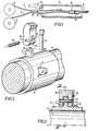
- the reference 1 designates the conduit inside which is carried out, in the direction indicated by the arrow, the positioning of the cable 2, by traction, by means of a pulling wire 4.
- tractor wire is previously introduced by its free end into the conduit 1 which it crosses in its entirety. Then, as the cable 2 of its reel 3 and that of the wire 4 of its reel 5 progresses, upstream of the inlet of the conduit 1, the cable 2 is fixed to the towing wire 4 by means of devices. coupling 6, at points A, B ... whose spacing is determined as a function of the tensile strength offered by the portion of cable thus defined, and with a little slack on the cable, so that each fraction of the said cable does not undergo any of the constraints of the fraction which precedes it.
- FIGS. 3 and 4 are partial sectional views of the device for Figure 2 after assembly.
- the cable fixing device 2 comprises a clamp 6 secured to the tractor wire 4 and provided with two elements forming jaws.
- Each of these elements is constituted by a first part 7 secured to the collar 6, in the form of an ear, in which an orifice 8 is formed, and by a second part 9 of generally arched shape, one of the ends of which is in the form of bracket 10 in which holes 11 and 12 are made.
- Each of the ears 7 is intended to be engaged in a corresponding stirrup 10.
- a pivot 13 arranged parallel to the axis of the pulling wire 4 and passing through the orifices 11, 8 and 12 connects the parts 7 and 9 so as to allow the latter to perform the required rotational movement, blocking them parts 7 and 9-10, in the closed position being obtained by means such as a blade 14 secured to the cellar 6 cooperating with a means such as a stop 16 secured to the pivoting part 9.
- the axis 13 can itself be locked in translation by any known means. It can thus for this purpose be provided at one of its ends with a head and at the other end with a pin or a groove associated with a spring finger fixed on the stirrup 10.
- Parts 9 provided to grip the cable 2 during its installation in the conduit, and only one of which can be articulated, as has already been indicated, have a generally arcuate shape, with a radius of curvature close to that of the cable so to marry the form therefore to improve the mechanical strength; their surface in contact with the cable can be striated transversely to the axis of the cable, preferably, to increase the grip.
- Figures 2 to 4 partially show only one of the two parts 9
- Figure 5 shows the two parts 9 in the clamping position on the cable 2 (solid lines) and in the position authorizing the release of said cable (broken lines).
- the remote control for opening or closing the jaws being common to all of them, preferably to limit the number of remote control wires, it is necessary to be able to open and close the one that arrives at the entrance to the conduit a given moment.
- a jaw can be opened manually by spreading the flexible blade 14 fixed at 15 to the collar 6.
- the remote controlled opening of the jaw by action on one or both of the parts 3 can be obtained by any suitable means allowing mechanical displacement to be determined.
- the jaw elements are arranged so as to act in a plane perpendicular to the axis of the cable.
- the jaw elements can be placed on the collar so as to act in a plane parallel to the axis of the cable.
- these elements designated by the reference 29 are arranged on the collar 26 longitudinally in the direction of the axis of the pulling wire 24.
- a spring such as 27, at will remote-controlled or not, which acts so as to separate the cable from the wire when the jaw is opened.
- This spring can be constituted as one of the elements 29 and therefore be remotely controlled at the same time as the opening thereof (bimetallic strip, etc.). It can also be passive and act permanently, its action having no effect. as long as the jaws are tight.
- a mechanical device can also be provided to disengage the action of spreading the cable when the latter is placed in the jaw.
- a fluid can be injected at high speed into said conduit, as shown at 17 in FIG. 1.
Landscapes
- Physics & Mathematics (AREA)
- General Physics & Mathematics (AREA)
- Optics & Photonics (AREA)
- Laying Of Electric Cables Or Lines Outside (AREA)
- Electric Cable Installation (AREA)
- Details Of Indoor Wiring (AREA)
- Supports For Pipes And Cables (AREA)
- Manipulator (AREA)
- Flexible Shafts (AREA)
- Cable Accessories (AREA)
Abstract
Description
- La présente invention concerne un procédé et des moyens de mise en place d'un câble de longueur importante, à l'intérieur d'un conduit, dans les meilleures conditions possibles, c'est-à-dire sans qu'il soit nécessaire d'exercer de trop fortes tractions sur le câble et en évitant le frottement de ce dernier contre la paroi du conduit. On sait que suivant la technique connue une telle opération s'effectue par traction sur l'extrémité libre du câble au moyen d'un fil tracteur préalablement introduit dans le conduit. Ce câble est alors déroulé du touret sur lequel il est enroulé au fur et à mesure de la progression à l'intérieur du conduit.
- Cette manière de procéder a l'inconvénient d'avoir une portée limitée par la résistance à la traction du câble, résistance qui doit vaincre celle constituée par le frottement , croissant, de ce dernier contre la paroi du conduit.
- L'invention a pour objet un procédé et des moyens permettant de remédier à cet inconvénient.
- Suivant ce procédé, le câble est fixé de façon temporaire, sur toute sa longueur, au fil tracteur par des moyens mécaniques, en des points dont l'espacement est déterminé en fonction de la résistance offerte à la traction par les fractions de câble ainsi délimitées, de manière à permettre d'effectuer la mise en place du câble en répartissant l'effort de traction sur des fractions successives du câble, le fil tracteur subissant quant à lui la totalité de l'effort de traction à son extrémité antérieure. Cette fixation du câble au fil tracteur peut être assurée par des moyens mécaniques, tels que collier de serrage ou pinces, fixés sur ce dernier et pourvus de deux éléments formant mâchoires entre lesquels peut être engagé le câble, l'un au moins des deux dits éléments étant articulé de manière à permettre de pouvoir serrer ou libérer manuellement le dit câble suivant l'effet requis, et pouvant être bloqué en position fermée par tous moyens connus.
- Suivant l'invention, l'écartement ou le serrage éventuel des éléments formant mâchoires peut également être télécommandé, par exemple thermiquement.
- A cet effet, ces éléments peuvent être constitués par des bilames prévus pour être chauffés sous l'effet d'un courant électrique amené,par exemple, par des moyens conducteurs développés le long du fil tracteur et qui peuvent agir sur l'un aussi bien que sur les deux bilames pour provoquer , suivant le type de bilame choisi et en considération du résultat recherché, soit l'écartement des mâchoires libérant ainsi le câble, soit au contraire leur serrage sur le câble.
- En outre, afin de réduire les effets de frottement de l'ensemble ainsi constitué par le fil tracteur et le câble contre la paroi du conduit, on peut introduire dans ce dernier, dans le sens du déplacement de l'ensemble, un fluide injecté à grande vitesse dont les turbulences et le contact avec le câble contribuent à l'avancement de ce dernier.
- Une telle injection présente également l'avantage d'assurer une lubrification ajoutant ses effets favorables à ceux précédemment indiqués qui résultent de l'application du procédé et des moyens en permettant la mise en oeuvre.
- On comprendra mieux les caractéristiques et avantages de l'invention en se référant à la description suivante et au dessin annexé donnant à titre non limitatif une forme de réalisation de l'invention.
-
- La figure 1 qui illustre le procédé suivant l'invention représente sous forme schématique, en coupe, un conduit, et, à l'intérieur de celui-ci un câble ainsi que son fil tracteur pourvu de moyens mécaniques de fixation permettant de relier le cable au fil tracteur de points en points, de manière à permettre d'effectuer la mise en place du câble par tractions successives.
- La figure 2 représente en vue perspective partielle éclatée, agrandie, un moyen de fixation , tel qu'un collier de serrage dans cet exemple, prévu pour relier le câble au fil tracteur.
- La figure 3 est une vue en coupe du moyen de fixation mécanique représenté sur la figure 2 après assemblage.
- La figure 4 est une vue en coupe suivant IV-IV de la figure 3.
- La figure 5 représente schématiquement le moyen mécanique de fixation en positions d'ouverture et de fermeture.
- Les figures 6 et 7 représentent une variante de réalisation du dispositif de fixation.
- La figure 8 représente schématiquement un moyen de commande magnétique appliqué au dispositif de l'invention.
- Les éléments communs à ces figures sont désignés par les mêmes références.
- Sur la figure 1, la référence 1 désigne le conduit à l'intérieur duquel est effectuée, dans le sens indiqué par la flèche, la mise en place du câble 2, par tractions, au moyen d'un fil tracteur 4.
- Il est précisé que le fil tracteur est préalablement introduit par son extrémité libre dans le conduit 1 qu'il traverse en son entier. Ensuite, au fur et à mesure du déroulement du câble 2 de son touret 3 et de celui du fil 4 de son touret 5, en amont de l'entrée du conduit 1, le câble 2 est fixé au fil tracteur 4 au moyen de dispositifs d'accouplement 6, en des points A, B... dont l'espacement est déterminé en fonction de la résistance offerte à la traction par la portion de câble ainsi définie, et avec un peu de mou sur le câble, de telle sorte que chaque fraction du dit câble ne subisse aucune des contraintes de la fraction qui la précède.
- La figure 2 représente en vue perspective éclatée, sous forme schématique simplifiée et à titre d'exemple, un dispositif d'accouplement mécanique du câble 2 au fil tracteur 4, tandis que les figures 3 et 4 sont des vues partielles en coupe du dispositif de la figure 2 après assemblage.
- Dans l'exemple de réalisation représenté sur les figures 2 à 4,le dispositif de fixation du câble 2 comprend un collier de serrage 6 solidaire du fil tracteur 4 et pourvu de deux éléments formant mâchoires. Chacun de ces éléments est constitué par une première pièce 7 solidaire du collier 6, en forme d'oreille, dans laquelle est pratiqué un orifice 8, et par une seconde pièce 9 de forme générale arquée, dont une des extrémités est en forme d'étrier 10 dans lequel sont pratiqués des orifices 11 et 12.
- Chacune des oreilles 7 est prévue pour être engagée dans un étrier 10 correspondant. Un pivot 13 disposé parallèlement à l'axe du fil tracteur 4 et passant par les orifices 11, 8 et 12 relie les pièces 7 et 9 de manière à permettre à cette dernière d'effectuer le mouvement de rotation requis, le blocage entre elles des pièces 7 et 9-10, en position fermée étant obtenu par un moyen tel qu'une lame 14 solidaire du cellier 6 coopérant avec un moyen tel qu'une butée 16 solidaire de la pièce pivotante 9.
- L'axe 13 peut âtre lui -même bloqué en translation par tout moyen connu. Il peut ainsi à cet effet être pourvu à l'une de ses extrémités d'une tête et à l'autre extrémité d'une goupille ou d'une gorge associée à un doigt à ressort fixé sur l'étrier 10. Les pièces 9 prévues pour enserrer le câble 2 au cours de sa mise en place dans le conduit, et dont une seule peut être articulée, comme il a déjà été indiqué, ont une forme générale arquée,avec un rayon de courbure voisin de celui du câble de façon à en épouser la forme donc à améliorer la tenue mécanique; leur surface en contact avec le câble peut être striée transversalement à l'axe du câble, de préférence, pour augmenter la prise.
- Tandis que les figures 2 à 4 représentent partiellement une seule des deux pièces 9, la figure 5 représente les deux pièces 9 en position de serrage sur le câble 2 (traits pleins) et en position autorisant la libération du dit câble (traits interrompus).
- La télécommande de l'ouverture ou de la fermeture des mâchoires étant commune à toutes celles-ci, de manière préférentielle pour limiter le nombre des fils de télécommande,il est nécessaire de pouvoir ouvrir et refermer celle qui arrive à l'entrée du conduit à un instant donné. A cet effet, dans l'exemple représenté, une mâchoire peut être ouverte manuellement en écartant la lame souple 14 fixée en 15 au collier 6.
- La butée 16 solidaire de l'élément de mâchoire correspondant 9 passe en dessous. Une fois le câble mis en place, on referme la mâchoire et on laisse retomber la lame 14 qui reprend sa position initiale.
- L'ouverture télécommandée de la mâchoire par action sur l'une ou sur les deux pièces 3 peut être obtenue par tout moyen approprié permettant de déterminer un déplacement mécanique.
- A titre d'exemple, on peut citer parmi ces moyens :
- - la commande par effet magnétique exerçant une force sur la mâchoire de manière à la faire pivoter en position d'ouverture. Cette disposition permet de supprimer la butée.
- - la commande par effet magnétique agissant sur un matériau perdant brutalement ses propriétés magnétiques au-dessus d'une certaine température: point de Curie. De l'énergie potentielle emmagasinée localement (dans un ressort, un aimant permanent non affecté par la température, etc...) fait basculer la mâchoire en position d'ouverture dès que le premier matériau (à point de Curie) ne s'oppose plus à l'action de l'énergie potentielle stockée, tel que représenté sur la figure 8 où l'aimant 30 est du type permanent.
- - la commande par effet thermique: la mâchoire est constituée à cet effet par un ou deux bilames prévus pour être chauffés électriquement sous l'effet d'un courant amené par des moyens conducteurs développés le long du câble tracteur, qui peuvent agir sur l'un aussi bien que sur les deux bilames. Ces conducteurs portent les références 28 et 29 sur la figure 5.
- Dans l'exemple représenté sur les figures 2, 3, 4, les éléments formant mâchoires sont disposés de façon à agir dans un plan perpendiculaire à l'axe du câble.
- Suivant une autre disposition représentée sur les figures 6 et 7, les éléments formant mâchoires peuvent être placés sur le collier de manière à agir dans un plan parallèle à l'axe du câble. Dans ce cas, ces éléments désignés par la référence 29 sont disposés sur le collier 26 longitudinalement dans le sens de l'axe du fil tracteur 24.
- Pour favoriser l'éjection du câble hors de la mâchoire, il est prévu un ressort tel que 27, à volonté télécommandé ou non, qui agit de façon à écarter le câble du fil lorsqu'on ouvre la mâchoire. Ce ressort peut être constitué comme l'un des éléments 29 et donc être télécommandé en même temps que l'ouverture de celui-ci (bilame , etc...) Il peut aussi être passif et agir en permanence,son action étant sans effet tant que les mâchoires sont serrées.
- Un dispositif mécanique peut également être prévu pour débrayer l'action d'écartement du câble lors de la mise en place de ce dernier dans la mâchoire.
- Comme il a été indiqué ci-dessus, pour favoriser l'avancement du câble et en réduire le frottement contre la paroi du conduit, un fluide peut être injecté à grande vitesse dans le dit conduit, tel que représenté en 17 sur la figure 1.
- Bien entendu toutes modifications apportées au dispositif décrit ci-dessus à titre d'exemple ne sortiraient pas du cadre de l'invention.
Claims (12)
Priority Applications (1)
| Application Number | Priority Date | Filing Date | Title |
|---|---|---|---|
| AT83400688T ATE21591T1 (de) | 1982-04-08 | 1983-04-01 | Vorrichtung zum verlegen eines kabels im rohrinneren. |
Applications Claiming Priority (2)
| Application Number | Priority Date | Filing Date | Title |
|---|---|---|---|
| FR8206121 | 1982-04-08 | ||
| FR8206121A FR2525036A1 (fr) | 1982-04-08 | 1982-04-08 | Procede et dispositif pour la mise en place d'un cable a l'interieur d'un conduit |
Publications (2)
| Publication Number | Publication Date |
|---|---|
| EP0091864A1 true EP0091864A1 (fr) | 1983-10-19 |
| EP0091864B1 EP0091864B1 (fr) | 1986-08-20 |
Family
ID=9272879
Family Applications (1)
| Application Number | Title | Priority Date | Filing Date |
|---|---|---|---|
| EP83400688A Expired EP0091864B1 (fr) | 1982-04-08 | 1983-04-01 | Dispositif de mise en place d'un câble à l'intérieur d'un conduit |
Country Status (14)
| Country | Link |
|---|---|
| US (1) | US4529172A (fr) |
| EP (1) | EP0091864B1 (fr) |
| JP (1) | JPS58204709A (fr) |
| AT (1) | ATE21591T1 (fr) |
| AU (1) | AU551983B2 (fr) |
| BR (1) | BR8301722A (fr) |
| CA (1) | CA1220467A (fr) |
| DE (1) | DE3365396D1 (fr) |
| DK (1) | DK155262C (fr) |
| ES (1) | ES8401810A1 (fr) |
| FR (1) | FR2525036A1 (fr) |
| IN (1) | IN158619B (fr) |
| MX (1) | MX158902A (fr) |
| ZA (1) | ZA832478B (fr) |
Cited By (1)
| Publication number | Priority date | Publication date | Assignee | Title |
|---|---|---|---|---|
| GB2217926A (en) * | 1988-04-22 | 1989-11-01 | Bicc Plc | Conveying an optical fibre member |
Families Citing this family (9)
| Publication number | Priority date | Publication date | Assignee | Title |
|---|---|---|---|---|
| JPS6129997A (ja) * | 1984-07-20 | 1986-02-12 | 日揮株式会社 | 火災検知システム |
| GB8520692D0 (en) * | 1985-08-19 | 1985-09-25 | Bicc Plc | Optical cable element |
| WO1990002286A1 (fr) * | 1988-08-22 | 1990-03-08 | Hex B-Group, Ltd. | Assemblage de garnissage interieur de conduite et procede d'installation associe |
| US5197716A (en) * | 1991-04-22 | 1993-03-30 | Shell Offshore Inc. | Seismic cable deployment apparatus |
| US5199659A (en) * | 1991-04-22 | 1993-04-06 | Shell Offshore Inc. | Seismic cable retrieval apparatus and method |
| US5556024A (en) * | 1994-09-29 | 1996-09-17 | International Business Machines Corporation | Apparatus and method for removing known good die using hot shear process |
| JP4328229B2 (ja) * | 2003-06-04 | 2009-09-09 | 株式会社ユニオン精密 | ねじ付属品を用いた締結体構造及びねじ付属品を用いた解体方法 |
| US8800967B2 (en) | 2009-03-23 | 2014-08-12 | Southwire Company, Llc | Integrated systems facilitating wire and cable installations |
| US10003179B2 (en) | 2008-01-21 | 2018-06-19 | Southwire Company, Llc | Integrated systems facilitating wire and cable installations |
Citations (4)
| Publication number | Priority date | Publication date | Assignee | Title |
|---|---|---|---|---|
| DE617657C (de) * | 1935-08-23 | Aeg | Verfahren zum Einziehen von elektrischen Kabeln in Rohre, Kanaele oder Furchen mittels eines Zugorgans | |
| DE1153810B (de) * | 1961-05-29 | 1963-09-05 | Richard Oertel | Vorrichtung zum Einziehen bzw. Ausziehen von elektrischen Kabeln in bzw. aus offenenGraeben, Furchen u. dgl. |
| CH460896A (de) * | 1967-04-21 | 1968-08-15 | Borel & Cie Expl Cabl El Syst | Verfahren zum Einbringen, Befestigen und Aufhängen von Kabeladern eines Druckrohrkabels in einem Druckrohr bei der Ueberwindung grosser Höhendifferenzen |
| EP0017616A1 (fr) * | 1979-03-27 | 1980-10-15 | Mathias Streiff AG | Procédé et dispositif pour la pose et la fixation de câbles électriques lourds |
Family Cites Families (4)
| Publication number | Priority date | Publication date | Assignee | Title |
|---|---|---|---|---|
| US1763634A (en) * | 1928-02-27 | 1930-06-10 | Agobian George | Vise |
| DE617656C (de) * | 1930-12-02 | 1935-08-23 | Aeg | Verfahren zum Einziehen von elektrischen Kabeln in Rohre mittels eines Zugorgans |
| US2575213A (en) * | 1946-01-04 | 1951-11-13 | Fruth Hal Frederick | Bimetallic fastener |
| NL7217620A (fr) * | 1972-12-22 | 1974-06-25 |
-
1982
- 1982-04-08 FR FR8206121A patent/FR2525036A1/fr active Granted
-
1983
- 1983-03-25 DK DK138183A patent/DK155262C/da not_active IP Right Cessation
- 1983-03-28 CA CA000424625A patent/CA1220467A/fr not_active Expired
- 1983-03-30 AU AU13054/83A patent/AU551983B2/en not_active Ceased
- 1983-04-01 EP EP83400688A patent/EP0091864B1/fr not_active Expired
- 1983-04-01 AT AT83400688T patent/ATE21591T1/de active
- 1983-04-01 DE DE8383400688T patent/DE3365396D1/de not_active Expired
- 1983-04-04 US US06/481,845 patent/US4529172A/en not_active Expired - Fee Related
- 1983-04-05 ES ES521213A patent/ES8401810A1/es not_active Expired
- 1983-04-05 BR BR8301722A patent/BR8301722A/pt not_active IP Right Cessation
- 1983-04-07 MX MX196870A patent/MX158902A/es unknown
- 1983-04-07 IN IN408/CAL/83A patent/IN158619B/en unknown
- 1983-04-08 JP JP58062047A patent/JPS58204709A/ja active Pending
- 1983-04-08 ZA ZA832478A patent/ZA832478B/xx unknown
Patent Citations (4)
| Publication number | Priority date | Publication date | Assignee | Title |
|---|---|---|---|---|
| DE617657C (de) * | 1935-08-23 | Aeg | Verfahren zum Einziehen von elektrischen Kabeln in Rohre, Kanaele oder Furchen mittels eines Zugorgans | |
| DE1153810B (de) * | 1961-05-29 | 1963-09-05 | Richard Oertel | Vorrichtung zum Einziehen bzw. Ausziehen von elektrischen Kabeln in bzw. aus offenenGraeben, Furchen u. dgl. |
| CH460896A (de) * | 1967-04-21 | 1968-08-15 | Borel & Cie Expl Cabl El Syst | Verfahren zum Einbringen, Befestigen und Aufhängen von Kabeladern eines Druckrohrkabels in einem Druckrohr bei der Ueberwindung grosser Höhendifferenzen |
| EP0017616A1 (fr) * | 1979-03-27 | 1980-10-15 | Mathias Streiff AG | Procédé et dispositif pour la pose et la fixation de câbles électriques lourds |
Cited By (2)
| Publication number | Priority date | Publication date | Assignee | Title |
|---|---|---|---|---|
| GB2217926A (en) * | 1988-04-22 | 1989-11-01 | Bicc Plc | Conveying an optical fibre member |
| GB2217926B (en) * | 1988-04-22 | 1991-11-20 | Bicc Plc | Method of conveying an optical fibre member and an apparatus for use therein |
Also Published As
| Publication number | Publication date |
|---|---|
| DK155262B (da) | 1989-03-13 |
| IN158619B (fr) | 1986-12-27 |
| MX158902A (es) | 1989-03-29 |
| ES521213A0 (es) | 1984-01-01 |
| AU551983B2 (en) | 1986-05-15 |
| FR2525036A1 (fr) | 1983-10-14 |
| US4529172A (en) | 1985-07-16 |
| DK155262C (da) | 1989-07-31 |
| ES8401810A1 (es) | 1984-01-01 |
| DK138183D0 (da) | 1983-03-25 |
| FR2525036B1 (fr) | 1985-03-15 |
| JPS58204709A (ja) | 1983-11-29 |
| AU1305483A (en) | 1983-10-13 |
| DK138183A (da) | 1983-10-09 |
| DE3365396D1 (en) | 1986-09-25 |
| EP0091864B1 (fr) | 1986-08-20 |
| ATE21591T1 (de) | 1986-09-15 |
| CA1220467A (fr) | 1987-04-14 |
| ZA832478B (en) | 1983-12-28 |
| BR8301722A (pt) | 1983-12-13 |
Similar Documents
| Publication | Publication Date | Title |
|---|---|---|
| EP0631357B1 (fr) | Support tubulaire de pose d'un manchon élastique rétractable | |
| EP0063506B1 (fr) | Dispositif de protection de fibres optiques dégagées à l'extrémité d'un élément de câble, élément de câble muni de ce dispositif, et utilisation d'un tel élément de câble | |
| EP1581830A1 (fr) | Bobine de conditionnement avec dispositif de vidage de cable optique | |
| EP0091864B1 (fr) | Dispositif de mise en place d'un câble à l'intérieur d'un conduit | |
| CA2381256A1 (fr) | Dispositif de guidage d'au moins un element longiligne souple, tel que cable ou autre, a contour substantiellement ferme | |
| FR2549923A1 (fr) | Serre-cable de frettage | |
| EP0271413A1 (fr) | Connecteur par déplacement d'isolant pour câble monoconducteur | |
| CA1245420A (fr) | Dispositif pour la realisation de galeries dans les cloisons composites | |
| FR2761826A1 (fr) | Outil et procede de gainage de cables | |
| EP3645912B1 (fr) | Dispositif et procede de blocage en tension d'un cable a l'aide d'une pince serre-cable | |
| FR2743932A1 (fr) | Outil de gainage d'un faisceau de fils | |
| FR3137510A1 (fr) | Dispositif de raccordement électrique et son procédé de production | |
| EP0933856B1 (fr) | Manchon d'étanchéité rétractable à froid pour câble électrique | |
| FR2543745A1 (fr) | Borne de serrage sans vis | |
| EP0822427A1 (fr) | Outil de découpe de l'enveloppe tubulaire d'un câble à fibres optiques | |
| EP3358679A1 (fr) | Dispositif de connexion d'un conducteur | |
| EP1331713A1 (fr) | Outil d'engainage d'au moins un câble dans une gaine fendue longitudinalement, et dispositif d'engainage comportant un tel outil | |
| FR3053520A1 (fr) | Poignee came pour mise en place d'un manchon retractable a froid a l'extremite d'un cable ou autour d'une jonction entre deux cables | |
| FR2677820A1 (fr) | Dispositif pour la separation de la tete d'un cable, notamment de telecommunications, et d'un furet de tirage dans une conduite. | |
| FR2652070A1 (fr) | Dispositif enrouleur et derouleur de cable. | |
| EP0052062A1 (fr) | Dispositif pour la fixation d'un câble électrique aérien à un isolateur | |
| WO1997017626A1 (fr) | Procede pour denuder une fibre optique ou un ruban de fibres optiques et appareil pour sa mise en oeuvre | |
| EP0205372A1 (fr) | Dispositif de guidage pour une portion de câble ou de faisceau de câbles de raccordement entre un boîtier fixe et une partie mobile articulée | |
| FR2506528A1 (fr) | Dispositif de connexion destine au raccordement d'une extremite d'un fil a un appareil electrique | |
| WO1995031027A1 (fr) | Pince d'attache pour cable aerien de telecommunications |
Legal Events
| Date | Code | Title | Description |
|---|---|---|---|
| PUAI | Public reference made under article 153(3) epc to a published international application that has entered the european phase |
Free format text: ORIGINAL CODE: 0009012 |
|
| AK | Designated contracting states |
Designated state(s): AT BE CH DE FR GB IT LI LU NL SE |
|
| 17P | Request for examination filed |
Effective date: 19840309 |
|
| ITF | It: translation for a ep patent filed | ||
| GRAA | (expected) grant |
Free format text: ORIGINAL CODE: 0009210 |
|
| AK | Designated contracting states |
Kind code of ref document: B1 Designated state(s): AT BE CH DE FR GB IT LI LU NL SE |
|
| REF | Corresponds to: |
Ref document number: 21591 Country of ref document: AT Date of ref document: 19860915 Kind code of ref document: T |
|
| REF | Corresponds to: |
Ref document number: 3365396 Country of ref document: DE Date of ref document: 19860925 |
|
| PG25 | Lapsed in a contracting state [announced via postgrant information from national office to epo] |
Ref country code: LU Free format text: LAPSE BECAUSE OF NON-PAYMENT OF DUE FEES Effective date: 19870430 |
|
| PLBE | No opposition filed within time limit |
Free format text: ORIGINAL CODE: 0009261 |
|
| STAA | Information on the status of an ep patent application or granted ep patent |
Free format text: STATUS: NO OPPOSITION FILED WITHIN TIME LIMIT |
|
| 26N | No opposition filed | ||
| PGFP | Annual fee paid to national office [announced via postgrant information from national office to epo] |
Ref country code: LU Payment date: 19900319 Year of fee payment: 8 |
|
| PGFP | Annual fee paid to national office [announced via postgrant information from national office to epo] |
Ref country code: CH Payment date: 19900323 Year of fee payment: 8 |
|
| PGFP | Annual fee paid to national office [announced via postgrant information from national office to epo] |
Ref country code: SE Payment date: 19900330 Year of fee payment: 8 |
|
| PGFP | Annual fee paid to national office [announced via postgrant information from national office to epo] |
Ref country code: GB Payment date: 19900331 Year of fee payment: 8 |
|
| PGFP | Annual fee paid to national office [announced via postgrant information from national office to epo] |
Ref country code: FR Payment date: 19900427 Year of fee payment: 8 Ref country code: AT Payment date: 19900427 Year of fee payment: 8 |
|
| ITTA | It: last paid annual fee | ||
| PGFP | Annual fee paid to national office [announced via postgrant information from national office to epo] |
Ref country code: NL Payment date: 19900430 Year of fee payment: 8 |
|
| ITPR | It: changes in ownership of a european patent |
Owner name: CESSIONE;JS TELECOM |
|
| PGFP | Annual fee paid to national office [announced via postgrant information from national office to epo] |
Ref country code: BE Payment date: 19900515 Year of fee payment: 8 |
|
| REG | Reference to a national code |
Ref country code: CH Ref legal event code: PUE Owner name: JS TELECOM |
|
| REG | Reference to a national code |
Ref country code: GB Ref legal event code: 732 |
|
| PGFP | Annual fee paid to national office [announced via postgrant information from national office to epo] |
Ref country code: DE Payment date: 19900621 Year of fee payment: 8 |
|
| NLS | Nl: assignments of ep-patents |
Owner name: JS TELECOM TE LOUVECIENNES, FRANKRIJK. |
|
| REG | Reference to a national code |
Ref country code: FR Ref legal event code: TP |
|
| PG25 | Lapsed in a contracting state [announced via postgrant information from national office to epo] |
Ref country code: GB Effective date: 19910401 Ref country code: AT Effective date: 19910401 |
|
| PG25 | Lapsed in a contracting state [announced via postgrant information from national office to epo] |
Ref country code: SE Effective date: 19910402 |
|
| PG25 | Lapsed in a contracting state [announced via postgrant information from national office to epo] |
Ref country code: LI Effective date: 19910430 Ref country code: CH Effective date: 19910430 Ref country code: BE Effective date: 19910430 |
|
| BERE | Be: lapsed |
Owner name: JS TELECOM Effective date: 19910430 |
|
| PG25 | Lapsed in a contracting state [announced via postgrant information from national office to epo] |
Ref country code: NL Effective date: 19911101 |
|
| GBPC | Gb: european patent ceased through non-payment of renewal fee | ||
| NLV4 | Nl: lapsed or anulled due to non-payment of the annual fee | ||
| PG25 | Lapsed in a contracting state [announced via postgrant information from national office to epo] |
Ref country code: FR Effective date: 19911230 |
|
| REG | Reference to a national code |
Ref country code: CH Ref legal event code: PL |
|
| PG25 | Lapsed in a contracting state [announced via postgrant information from national office to epo] |
Ref country code: DE Effective date: 19920201 |
|
| REG | Reference to a national code |
Ref country code: FR Ref legal event code: ST |
|
| EUG | Se: european patent has lapsed |
Ref document number: 83400688.4 Effective date: 19911108 |