EP0091926B1 - Procede et dispositif ameliores d'annulation de vibrations - Google Patents
Procede et dispositif ameliores d'annulation de vibrations Download PDFInfo
- Publication number
- EP0091926B1 EP0091926B1 EP82903154A EP82903154A EP0091926B1 EP 0091926 B1 EP0091926 B1 EP 0091926B1 EP 82903154 A EP82903154 A EP 82903154A EP 82903154 A EP82903154 A EP 82903154A EP 0091926 B1 EP0091926 B1 EP 0091926B1
- Authority
- EP
- European Patent Office
- Prior art keywords
- vibrations
- components
- residual
- pairs
- frequency domain
- Prior art date
- Legal status (The legal status is an assumption and is not a legal conclusion. Google has not performed a legal analysis and makes no representation as to the accuracy of the status listed.)
- Expired
Links
- 238000000034 method Methods 0.000 title claims abstract description 25
- 230000003252 repetitive effect Effects 0.000 claims abstract description 16
- 230000001131 transforming effect Effects 0.000 claims abstract description 6
- 230000004048 modification Effects 0.000 claims description 6
- 238000012986 modification Methods 0.000 claims description 6
- 230000003993 interaction Effects 0.000 claims description 5
- 230000001360 synchronised effect Effects 0.000 claims description 5
- 238000012544 monitoring process Methods 0.000 claims 2
- 239000007787 solid Substances 0.000 abstract description 3
- 239000007789 gas Substances 0.000 abstract 1
- 239000007788 liquid Substances 0.000 abstract 1
- 238000012546 transfer Methods 0.000 description 9
- 230000004044 response Effects 0.000 description 8
- 230000008859 change Effects 0.000 description 7
- 238000013459 approach Methods 0.000 description 6
- 230000008901 benefit Effects 0.000 description 3
- 230000008569 process Effects 0.000 description 3
- 230000003044 adaptive effect Effects 0.000 description 2
- 239000004020 conductor Substances 0.000 description 2
- 238000006880 cross-coupling reaction Methods 0.000 description 2
- 230000000694 effects Effects 0.000 description 2
- 239000011159 matrix material Substances 0.000 description 2
- 230000002441 reversible effect Effects 0.000 description 2
- 230000009466 transformation Effects 0.000 description 2
- 238000012935 Averaging Methods 0.000 description 1
- 206010013710 Drug interaction Diseases 0.000 description 1
- 238000009825 accumulation Methods 0.000 description 1
- 230000003466 anti-cipated effect Effects 0.000 description 1
- 230000005540 biological transmission Effects 0.000 description 1
- 238000004364 calculation method Methods 0.000 description 1
- 238000012512 characterization method Methods 0.000 description 1
- 230000007812 deficiency Effects 0.000 description 1
- 238000010586 diagram Methods 0.000 description 1
- 230000036039 immunity Effects 0.000 description 1
- 230000010363 phase shift Effects 0.000 description 1
- 238000001228 spectrum Methods 0.000 description 1
Images

Classifications
-
- F—MECHANICAL ENGINEERING; LIGHTING; HEATING; WEAPONS; BLASTING
- F16—ENGINEERING ELEMENTS AND UNITS; GENERAL MEASURES FOR PRODUCING AND MAINTAINING EFFECTIVE FUNCTIONING OF MACHINES OR INSTALLATIONS; THERMAL INSULATION IN GENERAL
- F16F—SPRINGS; SHOCK-ABSORBERS; MEANS FOR DAMPING VIBRATION
- F16F15/00—Suppression of vibrations in systems; Means or arrangements for avoiding or reducing out-of-balance forces, e.g. due to motion
- F16F15/02—Suppression of vibrations of non-rotating, e.g. reciprocating systems; Suppression of vibrations of rotating systems by use of members not moving with the rotating systems
-
- G—PHYSICS
- G10—MUSICAL INSTRUMENTS; ACOUSTICS
- G10K—SOUND-PRODUCING DEVICES; METHODS OR DEVICES FOR PROTECTING AGAINST, OR FOR DAMPING, NOISE OR OTHER ACOUSTIC WAVES IN GENERAL; ACOUSTICS NOT OTHERWISE PROVIDED FOR
- G10K11/00—Methods or devices for transmitting, conducting or directing sound in general; Methods or devices for protecting against, or for damping, noise or other acoustic waves in general
- G10K11/16—Methods or devices for protecting against, or for damping, noise or other acoustic waves in general
- G10K11/175—Methods or devices for protecting against, or for damping, noise or other acoustic waves in general using interference effects; Masking sound
- G10K11/178—Methods or devices for protecting against, or for damping, noise or other acoustic waves in general using interference effects; Masking sound by electro-acoustically regenerating the original acoustic waves in anti-phase
- G10K11/1785—Methods, e.g. algorithms; Devices
- G10K11/17853—Methods, e.g. algorithms; Devices of the filter
- G10K11/17854—Methods, e.g. algorithms; Devices of the filter the filter being an adaptive filter
-
- G—PHYSICS
- G10—MUSICAL INSTRUMENTS; ACOUSTICS
- G10K—SOUND-PRODUCING DEVICES; METHODS OR DEVICES FOR PROTECTING AGAINST, OR FOR DAMPING, NOISE OR OTHER ACOUSTIC WAVES IN GENERAL; ACOUSTICS NOT OTHERWISE PROVIDED FOR
- G10K11/00—Methods or devices for transmitting, conducting or directing sound in general; Methods or devices for protecting against, or for damping, noise or other acoustic waves in general
- G10K11/16—Methods or devices for protecting against, or for damping, noise or other acoustic waves in general
- G10K11/175—Methods or devices for protecting against, or for damping, noise or other acoustic waves in general using interference effects; Masking sound
- G10K11/178—Methods or devices for protecting against, or for damping, noise or other acoustic waves in general using interference effects; Masking sound by electro-acoustically regenerating the original acoustic waves in anti-phase
- G10K11/1785—Methods, e.g. algorithms; Devices
- G10K11/17857—Geometric disposition, e.g. placement of microphones
-
- G—PHYSICS
- G10—MUSICAL INSTRUMENTS; ACOUSTICS
- G10K—SOUND-PRODUCING DEVICES; METHODS OR DEVICES FOR PROTECTING AGAINST, OR FOR DAMPING, NOISE OR OTHER ACOUSTIC WAVES IN GENERAL; ACOUSTICS NOT OTHERWISE PROVIDED FOR
- G10K11/00—Methods or devices for transmitting, conducting or directing sound in general; Methods or devices for protecting against, or for damping, noise or other acoustic waves in general
- G10K11/16—Methods or devices for protecting against, or for damping, noise or other acoustic waves in general
- G10K11/175—Methods or devices for protecting against, or for damping, noise or other acoustic waves in general using interference effects; Masking sound
- G10K11/178—Methods or devices for protecting against, or for damping, noise or other acoustic waves in general using interference effects; Masking sound by electro-acoustically regenerating the original acoustic waves in anti-phase
- G10K11/1787—General system configurations
- G10K11/17879—General system configurations using both a reference signal and an error signal
- G10K11/17881—General system configurations using both a reference signal and an error signal the reference signal being an acoustic signal, e.g. recorded with a microphone
-
- G—PHYSICS
- G10—MUSICAL INSTRUMENTS; ACOUSTICS
- G10K—SOUND-PRODUCING DEVICES; METHODS OR DEVICES FOR PROTECTING AGAINST, OR FOR DAMPING, NOISE OR OTHER ACOUSTIC WAVES IN GENERAL; ACOUSTICS NOT OTHERWISE PROVIDED FOR
- G10K11/00—Methods or devices for transmitting, conducting or directing sound in general; Methods or devices for protecting against, or for damping, noise or other acoustic waves in general
- G10K11/16—Methods or devices for protecting against, or for damping, noise or other acoustic waves in general
- G10K11/175—Methods or devices for protecting against, or for damping, noise or other acoustic waves in general using interference effects; Masking sound
- G10K11/178—Methods or devices for protecting against, or for damping, noise or other acoustic waves in general using interference effects; Masking sound by electro-acoustically regenerating the original acoustic waves in anti-phase
- G10K11/1787—General system configurations
- G10K11/17879—General system configurations using both a reference signal and an error signal
- G10K11/17883—General system configurations using both a reference signal and an error signal the reference signal being derived from a machine operating condition, e.g. engine RPM or vehicle speed
-
- G—PHYSICS
- G10—MUSICAL INSTRUMENTS; ACOUSTICS
- G10K—SOUND-PRODUCING DEVICES; METHODS OR DEVICES FOR PROTECTING AGAINST, OR FOR DAMPING, NOISE OR OTHER ACOUSTIC WAVES IN GENERAL; ACOUSTICS NOT OTHERWISE PROVIDED FOR
- G10K2210/00—Details of active noise control [ANC] covered by G10K11/178 but not provided for in any of its subgroups
- G10K2210/10—Applications
- G10K2210/112—Ducts
-
- G—PHYSICS
- G10—MUSICAL INSTRUMENTS; ACOUSTICS
- G10K—SOUND-PRODUCING DEVICES; METHODS OR DEVICES FOR PROTECTING AGAINST, OR FOR DAMPING, NOISE OR OTHER ACOUSTIC WAVES IN GENERAL; ACOUSTICS NOT OTHERWISE PROVIDED FOR
- G10K2210/00—Details of active noise control [ANC] covered by G10K11/178 but not provided for in any of its subgroups
- G10K2210/30—Means
- G10K2210/301—Computational
- G10K2210/3019—Cross-terms between multiple in's and out's
-
- G—PHYSICS
- G10—MUSICAL INSTRUMENTS; ACOUSTICS
- G10K—SOUND-PRODUCING DEVICES; METHODS OR DEVICES FOR PROTECTING AGAINST, OR FOR DAMPING, NOISE OR OTHER ACOUSTIC WAVES IN GENERAL; ACOUSTICS NOT OTHERWISE PROVIDED FOR
- G10K2210/00—Details of active noise control [ANC] covered by G10K11/178 but not provided for in any of its subgroups
- G10K2210/30—Means
- G10K2210/301—Computational
- G10K2210/3023—Estimation of noise, e.g. on error signals
- G10K2210/30232—Transfer functions, e.g. impulse response
-
- G—PHYSICS
- G10—MUSICAL INSTRUMENTS; ACOUSTICS
- G10K—SOUND-PRODUCING DEVICES; METHODS OR DEVICES FOR PROTECTING AGAINST, OR FOR DAMPING, NOISE OR OTHER ACOUSTIC WAVES IN GENERAL; ACOUSTICS NOT OTHERWISE PROVIDED FOR
- G10K2210/00—Details of active noise control [ANC] covered by G10K11/178 but not provided for in any of its subgroups
- G10K2210/30—Means
- G10K2210/301—Computational
- G10K2210/3025—Determination of spectrum characteristics, e.g. FFT
-
- G—PHYSICS
- G10—MUSICAL INSTRUMENTS; ACOUSTICS
- G10K—SOUND-PRODUCING DEVICES; METHODS OR DEVICES FOR PROTECTING AGAINST, OR FOR DAMPING, NOISE OR OTHER ACOUSTIC WAVES IN GENERAL; ACOUSTICS NOT OTHERWISE PROVIDED FOR
- G10K2210/00—Details of active noise control [ANC] covered by G10K11/178 but not provided for in any of its subgroups
- G10K2210/30—Means
- G10K2210/301—Computational
- G10K2210/3045—Multiple acoustic inputs, single acoustic output
-
- G—PHYSICS
- G10—MUSICAL INSTRUMENTS; ACOUSTICS
- G10K—SOUND-PRODUCING DEVICES; METHODS OR DEVICES FOR PROTECTING AGAINST, OR FOR DAMPING, NOISE OR OTHER ACOUSTIC WAVES IN GENERAL; ACOUSTICS NOT OTHERWISE PROVIDED FOR
- G10K2210/00—Details of active noise control [ANC] covered by G10K11/178 but not provided for in any of its subgroups
- G10K2210/30—Means
- G10K2210/301—Computational
- G10K2210/3046—Multiple acoustic inputs, multiple acoustic outputs
-
- G—PHYSICS
- G10—MUSICAL INSTRUMENTS; ACOUSTICS
- G10K—SOUND-PRODUCING DEVICES; METHODS OR DEVICES FOR PROTECTING AGAINST, OR FOR DAMPING, NOISE OR OTHER ACOUSTIC WAVES IN GENERAL; ACOUSTICS NOT OTHERWISE PROVIDED FOR
- G10K2210/00—Details of active noise control [ANC] covered by G10K11/178 but not provided for in any of its subgroups
- G10K2210/50—Miscellaneous
- G10K2210/505—Echo cancellation, e.g. multipath-, ghost- or reverberation-cancellation
Definitions
- the invention relates to an improved method for cancelling vibrations (which may be gas-, liquid- or solid-borne) by nulling primary vibrations, at least in part, with specially generated cancelling or secondary vibrations.
- the invention also extends to vibration nulling apparatus based on the said improved method.
- the waveform of the required cancelling, or secondary vibrations can be synthesised from waveform elements synchronised with the repeat cycle of the primary vibrations.
- the most important feature of such a repetitive cancelling method is that by generating a synchronised waveform for cancellation, the feedback can be applied on the following repeat cycle, thus providing a capability to compensate for the inherent acoustic delay.
- a time domain approach has been used for adjusting waveform elements of the secondary vibrations to minimise the power or the waveform of the residual vibrations at the null point.
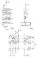
- Figure 1 shows a case where the primary vibrations (P) are noise travelling in a gas-filled duct D, but the principle applies equally to free-space noise transmissions, or vibrations transmitted through solid bodies.
- a method for cancelling repetitive vibrations comprises sensing the residual vibrations resulting from interference between primary vibrations from a source of repetitive vibrations and secondary vibrations from a driven actuator, transforming the sensed residual vibrations into a plurality of independent pairs of components which together define the residual vibrations at a plurality of different locations in the frequency domain, each synchronised to the repeat period of the repetitive primary vibrations from the source, separately modifying each component of each pair of components, transforming the said independent pairs of components back into a drive signal for the actuator and controlling the separate modification of the components of the pairs of components to reduce the power or amplitude of the residual vibrations.
- the independent pairs of components defining the residual vibrations at each of the different locations in the frequency domain can be the amplitudes of the real and imaginary sinusoidal components or the amplitude of the real sinusoidal component and a phase component.
- the different frequencies are desirably the first "n" harmonics (e.g. the second, third, etc., harmonics up to (say) the fifth or better the tenth harmonic) of the fundamental frequency.
- the fundamental frequency may change (e.g. when cancelling noise from a vehicle engine) it may be better to choose a larger number of frequencies, the lowest of which will represent the lowest expected fundamental and the highest of which will represent the "nth" harmonic corresponding to the highest anticipated fundamental.
- the method of the invention differs fundamentally from the unsuccessful earlier attempts, in two ways:
- the Fourier transform is a convenient reversible transform for employment in the invention since time waveforms and frequency spectra can be interchanged without introducing any modification. Thus, a time waveform can be re-constructed from the transformed frequency components, unlike the former filter approach shown in Figure 1.
- each frequency component of the residual vibrations (the error signal) will substantially only cause a response at the same frequency (although there may be inter-action between the in-phase and quadrature components), there is a unique relationship between any change in any given frequency component of the secondary vibrations and the resulting change in the amplitude of the same frequency component of the residual vibrations.
- a modification made to the waveform of a cancelling vibration from the actuator at a particular frequency comprises sine and cosine components.
- the resulting change in the residual (or error) signal can then also be expressed as the sum of two different amplitude components, by the relationship where
- any change made to the cancelling component can be used to calculate the transfer coefficients between the actuator and the residual sensor. These transfer coefficients can then be used in the next iteration of a cancellation algorithm to effect a close approximation to the cancellation required to produce a null at the residual sensor.
- a variety of algorithms can be used in the method of the invention to produce a very rapid approach to substantially complete cancellation. For example, when each modification is made, the transfer coefficients could be recalulated and the next calculation made on this new calculated value.
- a second possibility is to use the difference between the original, cancellation coefficient and the current coefficient to calculate the new transfer coefficient.
- transform modules used in the apparatus aspects of the invention could be Fourier transformers or some other transform module based upon a different mathematical series of independent functions which produces mutually independent components from a plurality of time domain samples.
- the transform modules can be implemented in analogue or digital form.
- a machine 10 e.g. a reciprocal linear machine or a rotating engine
- an electro-mechanical transducer or null sensor 11 e.g. a microphone
- a further electro-mechanical transducer or actuator 12 e.g. a loud-speaker
- secondary vibrations S which interact with the primary vibrations P in the location of the null sensor 11.
- the electrical output from the null sensor 11 is fed (via line 11a) to a commutator 13 to provide an analogue input 14 to a first Fourier transformer 15.
- a plurality of outputs 16 from the transformer 15, feed signals to a processor 17, which received synchronising pulses from the machine 10, via a synchronisation input 18.
- the signals on the outputs 16 are adapted, as described hereafter, to provide modified outputs 19 which provide the inputs to a second Fourier transformer 20.
- the analogue output 21 from the transformer 20 is fed to a commutator/driver 22 and thence (via line 12a) to the actuator 12.
- Figure 3 shows part of the apparatus of Figure 2 in greater detail.
- the time waveform on the line 11 a is sampled into a series of registers, by the commutator 13, these registers forming the input to the Fourier transformer 15.
- the outputs 16 and 19 in Figure 3 have been shown in pairs, one in solid line to show the real (or sine) component of that frequency and the other dashed to show the imaginary (or cosine) component of the same frequency.
- the individual harmonic components at each of the "n" frequencies are then processed in the processor 17 according to an adaptive algorithm (e.g. such as that shown earlier in equation A) and are presented to the second Fourier transformer 20 which converts the frequency domain samples back into time waveform samples, one on each part of the output 21.
- an adaptive algorithm e.g. such as that shown earlier in equation A
- These samples of the acquired time waveform are, of course, presented in synchronism with the operation of the machine 10 and are combined in the commutator/driver 22 to feed the line 12a.
- the Fourier transformer could be implemented in software, as a computer programme (see “The Fast Fourier Transform”-E. Oran Brigham-Prentice Hall), or in digital hardware emulating the Fourier transformer or "fast Fourier transform” computer programmes or in analogue hardware, one example of which is shown in Figure 5.
- Figure 5 shows a schematic part of a cross-coupled array of resistors linking vertical grid conductors (one for each of the time samples to, t 1 , t 2 ....t m ) and pairs of horizontal grid conductors, two pairs for each frequency component produced by the transformer, the outputs on one pair (S 1 +, S 1 -) being combined in a differential current summer 5 1 to give the sine component of the first harmonic and the outputs on the next pair (C1+, C,-) being combined in a second summer C, to give the cosine (or quadrature) component of the first harmonic. Further pairs of pairs are required for each subsequent harmonic, but only those for the sine component of the nth harmonic have been shown leading to a differential current summer S " .
- the outputs 16 from the transformer 15 have been shown in solid and dashed lines as in Figure 2.
- the locations of the resistors used for each cross coupling are only schematically illustrated in Figure 5 but are located and sized to provide a current proportionally to the sine (or cosine) of the respective harmonic.
- the simplest algorithm for adaption is successive trial and error, making incremental changes to the cancelling parameters to minimise the relevant power function at the residual measuring point.
- adaption of each component frequency can occur simultaneously.
- a faster adaption technique uses the amplitude of the residual signal to predict the modification needed to fully compensate for the residual error measured, rather than approach the adapted state by increments as in the heuristic adaption case discussed above.
- the transfer function between the actuator 12 and residual sensor 11, can be deduced in a number of ways. For example, a series of tones can be presented to the actuator and the resulting in-phase and quadrature components measured at the residual sensor, or an impulse can be presented to the actuator, Fourier analysed and the relationship between the in-phase and quadrature components of the source related to the in-phase and quadrature components at the residual sensor or a sample of random noise could be similarly processed. Any of these techniques will yield the amplitude and phase response between actuator and the residual sensor which can be used to infer the demanded signal at the actuator for cancelling any measured residual signal.
- the transformation from time domain to frequency samples requires a time history of the waveform to undergo a matrix multiplication by samples of the sinusoidal and cosinusoidal waveforms, or a mathematically equivalent operation (e.g. the first Fourier transformer).
- the transformation is reversible, and the original time waveform can be restored by an inverse transform, which process differs only slightly from the Fourier transform.
- the method and apparatus of the invention would be particularly suited to, although not limited to, any situation in which it is not possible to achieve a "suitable" phase response between a cancellation actuator and a residual sensor.
- a "suitable” phase response corresponds to a pure time delay for the previous fast adapting system.
- its application is not limited to this type of actuator/acoustic/sensor response, it could also be applied to other more well behaved actuators. Examples of systems with poor phase response include in-cab and in-room acoustics, vibration in structures and vibration in vessels and aircraft, and the invention shows particular promise in these applications.
Landscapes
- Engineering & Computer Science (AREA)
- Physics & Mathematics (AREA)
- Acoustics & Sound (AREA)
- Multimedia (AREA)
- General Engineering & Computer Science (AREA)
- Aviation & Aerospace Engineering (AREA)
- Mechanical Engineering (AREA)
- Soundproofing, Sound Blocking, And Sound Damping (AREA)
- Bridges Or Land Bridges (AREA)
- Diaphragms For Electromechanical Transducers (AREA)
- Audible-Bandwidth Dynamoelectric Transducers Other Than Pickups (AREA)
Claims (9)
Applications Claiming Priority (2)
| Application Number | Priority Date | Filing Date | Title |
|---|---|---|---|
| GB8131674 | 1981-10-21 | ||
| GB8131674 | 1981-10-21 |
Publications (2)
| Publication Number | Publication Date |
|---|---|
| EP0091926A1 EP0091926A1 (fr) | 1983-10-26 |
| EP0091926B1 true EP0091926B1 (fr) | 1987-08-26 |
Family
ID=10525294
Family Applications (1)
| Application Number | Title | Priority Date | Filing Date |
|---|---|---|---|
| EP82903154A Expired EP0091926B1 (fr) | 1981-10-21 | 1982-10-21 | Procede et dispositif ameliores d'annulation de vibrations |
Country Status (4)
| Country | Link |
|---|---|
| US (1) | US4490841A (fr) |
| EP (1) | EP0091926B1 (fr) |
| AU (1) | AU550818B2 (fr) |
| WO (1) | WO1983001525A1 (fr) |
Families Citing this family (71)
| Publication number | Priority date | Publication date | Assignee | Title |
|---|---|---|---|---|
| US4549289A (en) * | 1983-06-20 | 1985-10-22 | Jack Schwartz | Method for correcting acoustic distortion |
| US4628529A (en) * | 1985-07-01 | 1986-12-09 | Motorola, Inc. | Noise suppression system |
| US4630304A (en) * | 1985-07-01 | 1986-12-16 | Motorola, Inc. | Automatic background noise estimator for a noise suppression system |
| US4630305A (en) * | 1985-07-01 | 1986-12-16 | Motorola, Inc. | Automatic gain selector for a noise suppression system |
| US4677677A (en) * | 1985-09-19 | 1987-06-30 | Nelson Industries Inc. | Active sound attenuation system with on-line adaptive feedback cancellation |
| US4658426A (en) * | 1985-10-10 | 1987-04-14 | Harold Antin | Adaptive noise suppressor |
| US4677676A (en) * | 1986-02-11 | 1987-06-30 | Nelson Industries, Inc. | Active attenuation system with on-line modeling of speaker, error path and feedback pack |
| GB8603678D0 (en) * | 1986-02-14 | 1986-03-19 | Gen Electric Co Plc | Active noise control |
| US4736431A (en) * | 1986-10-23 | 1988-04-05 | Nelson Industries, Inc. | Active attenuation system with increased dynamic range |
| US4750523A (en) * | 1987-10-30 | 1988-06-14 | Beloit Corporation | Active attenuator and method |
| US4862506A (en) * | 1988-02-24 | 1989-08-29 | Noise Cancellation Technologies, Inc. | Monitoring, testing and operator controlling of active noise and vibration cancellation systems |
| US5119427A (en) * | 1988-03-14 | 1992-06-02 | Hersh Alan S | Extended frequency range Helmholtz resonators |
| US5016280A (en) * | 1988-03-23 | 1991-05-14 | Central Institute For The Deaf | Electronic filters, hearing aids and methods |
| US5225836A (en) * | 1988-03-23 | 1993-07-06 | Central Institute For The Deaf | Electronic filters, repeated signal charge conversion apparatus, hearing aids and methods |
| US4947435A (en) * | 1988-03-25 | 1990-08-07 | Active Noise & Vibration Tech | Method of transfer function generation and active noise cancellation in a vibrating system |
| EP0381898A3 (fr) * | 1988-12-27 | 1991-11-27 | Proto-Technology Corporation | Méthode et appareil pour annuler les vibrations de machines tournantes à paliers magnétiques |
| GB2229892A (en) * | 1989-03-28 | 1990-10-03 | Plessey Co Plc | An adaptive noise cancelling arrangement of a beamformer output |
| GB8929358D0 (en) * | 1989-12-30 | 1990-02-28 | 2020 Science Limited | Active vibration reducing system |
| US4999534A (en) * | 1990-01-19 | 1991-03-12 | Contraves Goerz Corporation | Active vibration reduction in apparatus with cross-coupling between control axes |
| US5237618A (en) * | 1990-05-11 | 1993-08-17 | General Electric Company | Electronic compensation system for elimination or reduction of inter-channel interference in noise cancellation systems |
| US5233540A (en) * | 1990-08-30 | 1993-08-03 | The Boeing Company | Method and apparatus for actively reducing repetitive vibrations |
| US5245552A (en) * | 1990-10-31 | 1993-09-14 | The Boeing Company | Method and apparatus for actively reducing multiple-source repetitive vibrations |
| US5255321A (en) * | 1990-12-05 | 1993-10-19 | Harman International Industries, Inc. | Acoustic transducer for automotive noise cancellation |
| GB9116433D0 (en) * | 1991-07-30 | 1991-09-11 | Active Noise & Vibration Tech | Noise reduction system |
| WO1993019458A1 (fr) * | 1992-03-19 | 1993-09-30 | Noise Cancellation Technologies, Inc. | Suppression electronique du bruit d'un moteur a courant continu |
| CA2117803A1 (fr) * | 1992-04-10 | 1993-10-28 | Jaime I. Chait | Elimination active de bruits ou de vibrations |
| US5313407A (en) * | 1992-06-03 | 1994-05-17 | Ford Motor Company | Integrated active vibration cancellation and machine diagnostic system |
| US5336856A (en) * | 1992-07-07 | 1994-08-09 | Arvin Industries, Inc. | Electronic muffler assembly with exhaust bypass |
| US5311453A (en) * | 1992-09-11 | 1994-05-10 | Noise Cancellation Technologies, Inc. | Variable point sampling |
| GB2271909B (en) * | 1992-10-21 | 1996-05-22 | Lotus Car | Adaptive control system |
| US5732143A (en) * | 1992-10-29 | 1998-03-24 | Andrea Electronics Corp. | Noise cancellation apparatus |
| WO1994020767A1 (fr) * | 1993-03-08 | 1994-09-15 | Noise Cancellation Technologies, Inc. | Procedes et appareil pour la commande en circuit ferme de paliers magnetiques |
| US5361303A (en) * | 1993-04-01 | 1994-11-01 | Noise Cancellation Technologies, Inc. | Frequency domain adaptive control system |
| US5416845A (en) * | 1993-04-27 | 1995-05-16 | Noise Cancellation Technologies, Inc. | Single and multiple channel block adaptive methods and apparatus for active sound and vibration control |
| US5539831A (en) * | 1993-08-16 | 1996-07-23 | The University Of Mississippi | Active noise control stethoscope |
| US5418857A (en) * | 1993-09-28 | 1995-05-23 | Noise Cancellation Technologies, Inc. | Active control system for noise shaping |
| US5473698A (en) * | 1993-11-23 | 1995-12-05 | Garnjost; Kenneth D. | Method of controlling the application of counter-vibration to a structure |
| US5502770A (en) * | 1993-11-29 | 1996-03-26 | Caterpillar Inc. | Indirectly sensed signal processing in active periodic acoustic noise cancellation |
| US5660255A (en) * | 1994-04-04 | 1997-08-26 | Applied Power, Inc. | Stiff actuator active vibration isolation system |
| DE4420439A1 (de) * | 1994-06-10 | 1995-12-14 | Stankiewicz Gmbh | Ladeflächenauskleidung mit integrierter Schallisolation |
| US5418858A (en) * | 1994-07-11 | 1995-05-23 | Cooper Tire & Rubber Company | Method and apparatus for intelligent active and semi-active vibration control |
| US5561598A (en) * | 1994-11-16 | 1996-10-01 | Digisonix, Inc. | Adaptive control system with selectively constrained ouput and adaptation |
| US5719791A (en) * | 1995-03-17 | 1998-02-17 | Georgia Tech Research Corporation | Methods, apparatus and systems for real time identification and control of modes of oscillation |
| US5615868A (en) * | 1995-10-04 | 1997-04-01 | Bolt Beranek And Newman Inc. | Active pneumatic mount |
| US5848168A (en) * | 1996-11-04 | 1998-12-08 | Tenneco Automotive Inc. | Active noise conditioning system |
| JPH10184747A (ja) * | 1996-12-19 | 1998-07-14 | Sumitomo Electric Ind Ltd | 車両ブレーキ用制振装置 |
| US6151397A (en) * | 1997-05-16 | 2000-11-21 | Motorola, Inc. | Method and system for reducing undesired signals in a communication environment |
| US6464489B1 (en) * | 1997-11-24 | 2002-10-15 | Alstom | Method and apparatus for controlling thermoacoustic vibrations in a combustion system |
| US6363345B1 (en) | 1999-02-18 | 2002-03-26 | Andrea Electronics Corporation | System, method and apparatus for cancelling noise |
| US6594367B1 (en) | 1999-10-25 | 2003-07-15 | Andrea Electronics Corporation | Super directional beamforming design and implementation |
| GB2361757B (en) | 2000-04-28 | 2003-12-03 | Bae Sys Electronics Ltd | Improvements in or relating to the damping of vibration |
| US6725101B2 (en) * | 2000-12-13 | 2004-04-20 | Xerox Corporation | Method and apparatus for using fast fourier transform feedback to compensate for non-linear motion |
| US20030016833A1 (en) * | 2001-07-19 | 2003-01-23 | Siemens Vdo Automotive, Inc. | Active noise cancellation system utilizing a signal delay to accommodate noise phase change |
| DE10213682A1 (de) * | 2002-03-27 | 2003-10-09 | Alstom Switzerland Ltd | Verfahren und Vorrichtung zur Kontrolle von thermoakustischen Instabilitäten bzw. Schwingungen in einem Verbrennungssystem |
| US7369115B2 (en) | 2002-04-25 | 2008-05-06 | Immersion Corporation | Haptic devices having multiple operational modes including at least one resonant mode |
| DE10257244A1 (de) * | 2002-12-07 | 2004-07-15 | Alstom Technology Ltd | Verfahren und Vorrichtung zur Beeinflussung thermoakustischer Schwingungen in Verbrennungssystemen |
| DE10257245A1 (de) * | 2002-12-07 | 2004-07-15 | Alstom Technology Ltd | Verfahren und Vorrichtung zur Beeinflussung thermoakustischer Schwingungen in Verbrennungssystemen |
| US7440821B1 (en) * | 2004-01-02 | 2008-10-21 | Sauer-Danfoss Inc. | Method of determining average current in a PWM drive |
| GB0416330D0 (en) * | 2004-07-22 | 2004-08-25 | Microgen Energy Ltd | Method and apparatus for instability detection and correction in a domestic combined heat and power unit |
| EP1703494A1 (fr) * | 2005-03-17 | 2006-09-20 | Emma Mixed Signal C.V. | Dispositif d'écoute |
| US8302456B2 (en) | 2006-02-23 | 2012-11-06 | Asylum Research Corporation | Active damping of high speed scanning probe microscope components |
| US7532927B1 (en) * | 2006-07-19 | 2009-05-12 | Pacesetter, Inc. | Implantable medical device and associated method for reducing an affect of a vibratory alert on a vibration-sensitive sensor |
| US20080187147A1 (en) * | 2007-02-05 | 2008-08-07 | Berner Miranda S | Noise reduction systems and methods |
| RU2339144C1 (ru) * | 2007-07-19 | 2008-11-20 | Юрий Владимирович Шаров | Способ улучшения динамической устойчивости и демпфирования колебаний электроэнергетических систем и устройство для его осуществления |
| US8800302B2 (en) * | 2012-07-16 | 2014-08-12 | Sunpower, Inc. | Driving an active vibration balancer to minimize vibrations at the fundamental and harmonic frequencies |
| US8860381B2 (en) | 2012-07-16 | 2014-10-14 | Sunpower, Inc. | Balancing vibrations at harmonic frequencies by injecting harmonic balancing signals into the armature of a linear motor/alternator coupled to a Stirling machine |
| JP5823362B2 (ja) * | 2012-09-18 | 2015-11-25 | 株式会社東芝 | 能動消音装置 |
| US9383388B2 (en) | 2014-04-21 | 2016-07-05 | Oxford Instruments Asylum Research, Inc | Automated atomic force microscope and the operation thereof |
| JP2018523108A (ja) * | 2015-06-12 | 2018-08-16 | プロフタガレン アクチエボラグProvtagaren Ab | 流量測定のためのパルス消去 |
| KR101855774B1 (ko) * | 2016-12-13 | 2018-06-20 | 현대자동차 주식회사 | 하이브리드 차량의 진동 제어 장치 및 방법 |
| CN112433371A (zh) * | 2020-10-22 | 2021-03-02 | 歌尔光学科技有限公司 | 头戴设备 |
Family Cites Families (6)
| Publication number | Priority date | Publication date | Assignee | Title |
|---|---|---|---|---|
| US3662108A (en) * | 1970-06-08 | 1972-05-09 | Bell Telephone Labor Inc | Apparatus for reducing multipath distortion of signals utilizing cepstrum technique |
| US4066842A (en) * | 1977-04-27 | 1978-01-03 | Bell Telephone Laboratories, Incorporated | Method and apparatus for cancelling room reverberation and noise pickup |
| GB2054999B (en) * | 1979-06-28 | 1983-09-07 | Nat Res Dev | Signal processing systems |
| JPH0740199B2 (ja) * | 1979-08-16 | 1995-05-01 | チャプリン パテンツ ホ−ルディング カンパニ− インコ−ポレ−テッド | 繰り返し振動の相殺の方法 |
| JPS5717027A (en) * | 1980-07-03 | 1982-01-28 | Hitachi Ltd | Vibration reducing device of electric machinery |
| GB2097629B (en) * | 1981-04-15 | 1984-09-26 | Nat Res Dev | Methods and apparatus for active sound control |
-
1982
- 1982-10-21 US US06/518,802 patent/US4490841A/en not_active Expired - Lifetime
- 1982-10-21 AU AU90523/82A patent/AU550818B2/en not_active Expired
- 1982-10-21 WO PCT/GB1982/000299 patent/WO1983001525A1/fr not_active Ceased
- 1982-10-21 EP EP82903154A patent/EP0091926B1/fr not_active Expired
Also Published As
| Publication number | Publication date |
|---|---|
| EP0091926A1 (fr) | 1983-10-26 |
| AU9052382A (en) | 1983-05-05 |
| AU550818B2 (en) | 1986-04-10 |
| WO1983001525A1 (fr) | 1983-04-28 |
| US4490841A (en) | 1984-12-25 |
Similar Documents
| Publication | Publication Date | Title |
|---|---|---|
| EP0091926B1 (fr) | Procede et dispositif ameliores d'annulation de vibrations | |
| US4878188A (en) | Selective active cancellation system for repetitive phenomena | |
| CA1318956C (fr) | Methode de generation de fonction de transfert et d'attenuation acoustique active pour systeme vibrant | |
| EP0695452B1 (fr) | Systeme de commande adaptatif dans le domaine frequentiel | |
| US5469087A (en) | Control system using harmonic filters | |
| GB2107960A (en) | Method and apparatus for cancelling vibrations | |
| EP0568128A2 (fr) | Système d'atténuation du bruit | |
| US20090175461A1 (en) | Active noise controller | |
| GB2222053A (en) | Signal processing means for sensing a periodic signal in the presence of another interfering periodic noise | |
| EP0654901A1 (fr) | Système de convergence rapide d'un filtre adaptative pour la génération d'un signal variant dans le temps pour l'annulation d'un signal primaire | |
| US5619581A (en) | Active noise and vibration cancellation system | |
| US20100111318A1 (en) | Active noise controller | |
| JP3732227B2 (ja) | 繰り返し事象を制御する適応制御システム | |
| US5953428A (en) | Feedback method of noise control having multiple inputs and outputs | |
| EP0647372A1 (fr) | Systeme de commande utilisant des filtres harmoniques | |
| WO1994000911A9 (fr) | Systeme de commande utilisant des filtres harmoniques | |
| WO1987002496A1 (fr) | Generation de fonctions de transfert pour la suppression active du bruit | |
| RU2798744C1 (ru) | Способ активного гашения вибраций | |
| DE68926039T2 (de) | Selektives aktives system zur unterdrückung von sich wiederholende erscheinungen | |
| JP2004020714A (ja) | 能動振動騒音低減装置 | |
| KR19990016276A (ko) | 능동소음제어에서의 제어신호 합성장치 | |
| NO160034B (no) | Fremgangsmaate og anordning til utligning av vibrasjoner. | |
| WO1993021688A1 (fr) | Elimination active du bruit ou de vibrations | |
| Al-Ajlouni | Adaptive ANC using generalized phase-locked loop | |
| WO1992008224A1 (fr) | Systeme actif de regulation de vibrations avec entrees multiples |
Legal Events
| Date | Code | Title | Description |
|---|---|---|---|
| PUAI | Public reference made under article 153(3) epc to a published international application that has entered the european phase |
Free format text: ORIGINAL CODE: 0009012 |
|
| AK | Designated contracting states |
Designated state(s): BE CH DE FR LI NL SE |
|
| 17P | Request for examination filed |
Effective date: 19831024 |
|
| RBV | Designated contracting states (corrected) |
Designated state(s): BE CH FR LI NL |
|
| GRAA | (expected) grant |
Free format text: ORIGINAL CODE: 0009210 |
|
| AK | Designated contracting states |
Kind code of ref document: B1 Designated state(s): BE CH FR LI NL |
|
| ET | Fr: translation filed | ||
| PLBE | No opposition filed within time limit |
Free format text: ORIGINAL CODE: 0009261 |
|
| STAA | Information on the status of an ep patent application or granted ep patent |
Free format text: STATUS: NO OPPOSITION FILED WITHIN TIME LIMIT |
|
| REG | Reference to a national code |
Ref country code: CH Ref legal event code: PLI Owner name: ACTIVE NOISE AND VIBRATION TECHNOLOGIES INC. (A DE |
|
| 26N | No opposition filed | ||
| REG | Reference to a national code |
Ref country code: FR Ref legal event code: CL |
|
| REG | Reference to a national code |
Ref country code: CH Ref legal event code: PUE Owner name: CHAPLIN PATENTS HOLDING CO. INC. C/O NOISE CANCELL Ref country code: CH Ref legal event code: PLIA Free format text: ACTIVE NOISE AND VIBRATION TECHNOLOGIES INC. (A DELAWARE CORPORATION) Ref country code: CH Ref legal event code: PLI Owner name: NOISE CANCELLATION TECHNOLOGIES INC. |
|
| REG | Reference to a national code |
Ref country code: FR Ref legal event code: TP Ref country code: FR Ref legal event code: RL Ref country code: FR Ref legal event code: CL |
|
| NLXE | Nl: other communications concerning ep-patents (part 3 heading xe) |
Free format text: IN PAT.BUL.20/88,HEADING UE,IS TERMINATED ACCORDING TO AN INSTRUMENT REGISTERED ON 900614 UNDER NO. 27308 |
|
| NLS | Nl: assignments of ep-patents |
Owner name: CHAPLIN PATENTS HOLDING CO INC. TE NEW YORK, NEW Y |
|
| PGFP | Annual fee paid to national office [announced via postgrant information from national office to epo] |
Ref country code: NL Payment date: 20010921 Year of fee payment: 20 |
|
| PGFP | Annual fee paid to national office [announced via postgrant information from national office to epo] |
Ref country code: FR Payment date: 20011005 Year of fee payment: 20 |
|
| PGFP | Annual fee paid to national office [announced via postgrant information from national office to epo] |
Ref country code: BE Payment date: 20011113 Year of fee payment: 20 |
|
| PGFP | Annual fee paid to national office [announced via postgrant information from national office to epo] |
Ref country code: CH Payment date: 20020103 Year of fee payment: 20 |
|
| PG25 | Lapsed in a contracting state [announced via postgrant information from national office to epo] |
Ref country code: LI Free format text: LAPSE BECAUSE OF EXPIRATION OF PROTECTION Effective date: 20021020 Ref country code: CH Free format text: LAPSE BECAUSE OF EXPIRATION OF PROTECTION Effective date: 20021020 |
|
| PG25 | Lapsed in a contracting state [announced via postgrant information from national office to epo] |
Ref country code: NL Free format text: LAPSE BECAUSE OF EXPIRATION OF PROTECTION Effective date: 20021021 |
|
| REG | Reference to a national code |
Ref country code: CH Ref legal event code: PL |
|
| NLV7 | Nl: ceased due to reaching the maximum lifetime of a patent |
Effective date: 20021021 |