EP0092045A2 - Transducteur électroacoustique avec support - Google Patents
Transducteur électroacoustique avec support Download PDFInfo
- Publication number
- EP0092045A2 EP0092045A2 EP83102224A EP83102224A EP0092045A2 EP 0092045 A2 EP0092045 A2 EP 0092045A2 EP 83102224 A EP83102224 A EP 83102224A EP 83102224 A EP83102224 A EP 83102224A EP 0092045 A2 EP0092045 A2 EP 0092045A2
- Authority
- EP
- European Patent Office
- Prior art keywords
- converter
- tongue
- holder according
- leg
- base
- Prior art date
- Legal status (The legal status is an assumption and is not a legal conclusion. Google has not performed a legal analysis and makes no representation as to the accuracy of the status listed.)
- Withdrawn
Links
Images
Classifications
-
- H—ELECTRICITY
- H04—ELECTRIC COMMUNICATION TECHNIQUE
- H04R—LOUDSPEAKERS, MICROPHONES, GRAMOPHONE PICK-UPS OR LIKE ACOUSTIC ELECTROMECHANICAL TRANSDUCERS; ELECTRIC HEARING AIDS; PUBLIC ADDRESS SYSTEMS
- H04R1/00—Details of transducers, loudspeakers or microphones
- H04R1/08—Mouthpieces; Microphones; Attachments therefor
- H04R1/083—Special constructions of mouthpieces
Definitions
- the invention relates to an electroacoustic transducer with a holder that can be detached and attached to a base.
- transducers with this type of holder have a clamp with two jaws encompassing the transducer housing. Their manufacture is complex and it is cumbersome to detach the transducer from the holder and to re-attach it to the holder.
- the invention has for its object to provide a converter with holder of the type mentioned, which is more economical, especially plastic and easier to handle.
- the embodiment according to claim 3 prevents that the tongue of the holder "rattles" in the guide of the transducer.
- the guide is arranged in a space-saving and aesthetically advantageous manner in a part of the converter housing interior that was previously not usually used.
- Claim 5 specifies preferred holder shapes.
- the holder is stiffened and can be designed so that the inclination of the transducer can be adjusted with respect to the base.
- Claim 12 relates to an embodiment that facilitates the loosening and attachment of the transducer to the holder without changing the selected inclination with respect to the base.
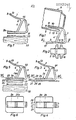
- 1 and 2 consists essentially of a plastic part which is approximately U-shaped curved. 1 and 2 denote the legs, 3 the part connecting them to each other. To reinforce the U-shape, a strut 4 is firmly connected to the legs 1 and 2.
- the leg 1 forms a tongue which has a locking bead 5 at the free end and a shoulder 6 at the other end, which is connected to the part 3 and the strut 4.
- a guide sleeve 10 is formed, in which the tongue 1 is inserted, its locking bead 5 engaging over the edge 11 at the inner end of the sleeve 10 and the shoulder 6 at the outer end 12 of the sleeve 10 on lies.
- the leg 2 (Fig..1 and 2) has two opposite side lugs 15 with recesses 16, for example for screws for attaching the holder to a base. If the base is approximately horizontal, the holder holds the transducer in the generally desired inclined position shown in FIG. 1. If the base is approximately vertical, this inclined position can be achieved in that the legs 1 and 2 enclose a larger angle, the part 3 may be smaller or omitted, so that the shape is approximately a V instead of approximately a U.
- the legs 1 and 2 can also be connected to one another by a friction-inhibited joint or a joint that can be fixed by means of a clamping screw, so that the inclination of the transducer can be adjusted, in the case of a ball joint it can be adjusted on all sides.
- a bead 17 at one end of the leg 2, in the place of which two projections may also be present, has the effect that the holder is held stable even when it is fastened to a curved support surface.
- the variant according to FIGS. 3 and 4 differs from the embodiment according to FIGS. 1 and 2 in that the leg 2a, which, like the leg 2 together with the leg 1 and the part 3, approximately forms a U-shape, is similar to that Leg 1 is a slightly curved tongue, which has a locking bead 22 at the free end and is inserted in a pocket-like cavity 23 of a base 24.
- the latching bead 22 engages in an opening 25 of the base, so that the holder can be detached from the base 24 and replaced again by overcoming the latching resistance when the tongue 2a is pulled out of the cavity 23.
- the base 24 has two tabs 26, with cutouts 27, for fastening screws or the like. For attachment to a base.
- the base 24a corresponds to the base 24 (FIGS. 3 and 4) but has no tabs 26, and in the third variant according to FIG. 7 the leg 2b is instead of leg 2 (FIGS. 1 and 2) or 2a (FIGS. 3-5) is provided on its underside with an adhesive coating 31, to which an adhesive coating 33 fastened on the base 32 is assigned.
- the commercially available adhesive coverings 31 and 33 can be self-adhesive, but are preferably form-fitting, one covering being a so-called hook band and the other a so-called loop band, or both coverings have a large number of small hemispherical heads.
- the pads 31 and 33 are glued to the base 24 and 24a and to the base 32.
- FIGS. 3 and 4 and FIGS. 5 and 6 and 7 make it possible to attach the transducer either at one of several locations, the are each provided with a base 24 or an adhesive covering 33. This also applies to the second embodiment according to FIGS. 8 and 9 and its variants.
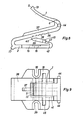
- the legs 1 and 2 which correspond structurally and functionally to the legs denoted by the same reference numbers in FIG. 1, are connected to one another by a third leg 36 to form a Z-shape.
- the third leg 36 is provided on its side facing the leg 1 with a stiffening rib 37 and on its other side facing the leg 2 with locking teeth 38.
- the ratchet teeth 38 together with a strut 39 form a ratchet which is not shown in FIG. locked state is shown.
- the strut 39 has a wedge-shaped end 40 which interacts with the locking teeth 38. Its other end is connected to the free end 42 of the leg 2 by a flexible connecting piece 41 of smaller cross section.
- the strut 39 When the strut 39 is pivoted upward, it bends the elastically yielding legs 36 and 2 apart, engages one of the locking teeth 38 and thereby keeps the leg 36 in a steeper position and the leg 1 with the (in FIGS. 8 and 9 not 7), which is plugged onto the leg 1 as shown in FIG. 7, in a position which is less inclined to the leg 2, which is fastened on the base.
- the strut 39 can be gripped on two projections 45 for adjustment.
- FIGS. 8 and 9 can also be carried out analogously to the variant according to FIGS. 3 and 4 or 5 and 6 or 7.
- the holder has projections 44, on which it can be held with one hand when the transducer is inserted or removed from the tongue 1 with the other hand or the ratchet is adjusted in FIG. 8.
- the holder is to be arranged so that the tongue 2a can be pulled out of the base 24 or 24a in the direction of travel.
- the transducer detached from the pad cannot cause any damage even if it bounces back on a surface because it is attached to its connection Cable, which must be secured at both ends accordingly.
- a base 24 or adhesive covering 33 can be provided at each of these locations.
- one of several transducers with a holder can alternatively be attached to a location provided with the base 24 or adhesive covering 33, or transducers with a holder can be exchanged for one another.
- the converter can also be replaced on each of the holders.
Landscapes
- Physics & Mathematics (AREA)
- Engineering & Computer Science (AREA)
- Acoustics & Sound (AREA)
- Signal Processing (AREA)
- Electrophonic Musical Instruments (AREA)
- Measuring Pulse, Heart Rate, Blood Pressure Or Blood Flow (AREA)
- Casings For Electric Apparatus (AREA)
Applications Claiming Priority (2)
| Application Number | Priority Date | Filing Date | Title |
|---|---|---|---|
| CH238282 | 1982-04-20 | ||
| CH2382/82 | 1982-04-20 |
Publications (2)
| Publication Number | Publication Date |
|---|---|
| EP0092045A2 true EP0092045A2 (fr) | 1983-10-26 |
| EP0092045A3 EP0092045A3 (fr) | 1985-10-02 |
Family
ID=4232467
Family Applications (1)
| Application Number | Title | Priority Date | Filing Date |
|---|---|---|---|
| EP83102224A Withdrawn EP0092045A3 (fr) | 1982-04-20 | 1983-03-07 | Transducteur électroacoustique avec support |
Country Status (2)
| Country | Link |
|---|---|
| EP (1) | EP0092045A3 (fr) |
| DE (1) | DE8225104U1 (fr) |
Cited By (1)
| Publication number | Priority date | Publication date | Assignee | Title |
|---|---|---|---|---|
| US10867504B2 (en) | 2019-04-25 | 2020-12-15 | Baker Hughes Oilfield Operations Llc | Monitoring of marshalling cabinet wiring |
Family Cites Families (5)
| Publication number | Priority date | Publication date | Assignee | Title |
|---|---|---|---|---|
| GB1084045A (fr) * | 1963-10-07 | |||
| DE7039493U (de) * | 1970-10-26 | 1971-01-21 | Sennheiser Electronic Sennheiser F | Federhalterung fur ein relativ langes Mikrofon |
| AT303145B (de) * | 1970-10-29 | 1972-11-10 | Akg Akustische Kino Geraete | Am Körper zu tragendes Mikrophon |
| US4055286A (en) * | 1975-12-22 | 1977-10-25 | Schmid Charles F | Portable mount for radios in motor vehicles |
| JPS5624898A (en) * | 1979-08-06 | 1981-03-10 | Mitsubishi Electric Corp | Switch mechanism material mike hooking jig |
-
1982
- 1982-09-06 DE DE19828225104 patent/DE8225104U1/de not_active Expired
-
1983
- 1983-03-07 EP EP83102224A patent/EP0092045A3/fr not_active Withdrawn
Cited By (1)
| Publication number | Priority date | Publication date | Assignee | Title |
|---|---|---|---|---|
| US10867504B2 (en) | 2019-04-25 | 2020-12-15 | Baker Hughes Oilfield Operations Llc | Monitoring of marshalling cabinet wiring |
Also Published As
| Publication number | Publication date |
|---|---|
| EP0092045A3 (fr) | 1985-10-02 |
| DE8225104U1 (de) | 1983-02-03 |
Similar Documents
| Publication | Publication Date | Title |
|---|---|---|
| DE69605618T2 (de) | Abstandsvorrichtung zur Verwendung mit einem Kabelbinder | |
| DE69622790T2 (de) | Halter für einen Funkrufempfänger | |
| DE3888174T2 (de) | Kabelmontagevorrichtung. | |
| DE3202750C2 (de) | Abdeckung für eine Öffnung in einem Frachtbehälter | |
| DE19908300C1 (de) | Bügelhalter für ein Handwerkzeug | |
| DE3227822A1 (de) | Chirurgischer retraktorklauenhalter | |
| DE3145664A1 (de) | "schutzhelm fuer den kopf mit verriegelungsmitteln" | |
| WO2019170380A1 (fr) | Siège de véhicule | |
| DE2830676A1 (de) | Skihaltevorrichtung | |
| DE3131801C2 (de) | Ansatzstück für Brillenbügel | |
| DE19503288C1 (de) | Schlafhilfe | |
| DE2357573C2 (de) | Zahnregulierungsklammer | |
| DE1138428B (de) | Brillenbuegelanordnung mit einer elektrischen Anlage, insbesondere einem Hoergeraet | |
| EP0158742B1 (fr) | Chariot porte-câble | |
| EP0092045A2 (fr) | Transducteur électroacoustique avec support | |
| DE3146815C2 (de) | Lagerung für eine Schlauchdüse mit Pistolengriff während deren Nichtbenutzung | |
| DE2062829B2 (de) | Schutzbrille mit seitenblenden | |
| DE2449767C2 (de) | Einsatz zur Reinigung von Anästhesie- Zubehör | |
| EP3995044A1 (fr) | Capuchon de brosse à dents et système d'hygiène dentaire | |
| DE3150049A1 (de) | Klammern (brackets) oder betaetigungselemente zum anbringen an den zaehnen fuer die zahnregulierung | |
| DE2840821A1 (de) | Sporen fuer reitstiefel | |
| DE10361146B4 (de) | Positionssicherungseinheit von Gehhilfen | |
| DE19544069C2 (de) | Haltevorrichtung für eine Steckkarte | |
| DE2129573A1 (de) | Orthopaedisches Geraet fuer die Zahn- und Gesichtsbehandlung | |
| DE19516021C1 (de) | Einführschutz für die Montage von Stiften oder Zapfen eines Hardtops |
Legal Events
| Date | Code | Title | Description |
|---|---|---|---|
| PUAI | Public reference made under article 153(3) epc to a published international application that has entered the european phase |
Free format text: ORIGINAL CODE: 0009012 |
|
| AK | Designated contracting states |
Designated state(s): AT BE CH DE FR GB IT LI NL SE |
|
| PUAL | Search report despatched |
Free format text: ORIGINAL CODE: 0009013 |
|
| AK | Designated contracting states |
Designated state(s): AT BE CH DE FR GB IT LI NL SE |
|
| STAA | Information on the status of an ep patent application or granted ep patent |
Free format text: STATUS: THE APPLICATION IS DEEMED TO BE WITHDRAWN |
|
| 18D | Application deemed to be withdrawn |
Effective date: 19851002 |