EP0092065B1 - Regeneration eines Katalysators, der bei der Konversion carbo-metallischer Rückstandsöle verwendet worden ist - Google Patents
Regeneration eines Katalysators, der bei der Konversion carbo-metallischer Rückstandsöle verwendet worden ist Download PDFInfo
- Publication number
- EP0092065B1 EP0092065B1 EP19830102928 EP83102928A EP0092065B1 EP 0092065 B1 EP0092065 B1 EP 0092065B1 EP 19830102928 EP19830102928 EP 19830102928 EP 83102928 A EP83102928 A EP 83102928A EP 0092065 B1 EP0092065 B1 EP 0092065B1
- Authority
- EP
- European Patent Office
- Prior art keywords
- catalyst
- regeneration
- stage
- oxygen
- bed
- Prior art date
- Legal status (The legal status is an assumption and is not a legal conclusion. Google has not performed a legal analysis and makes no representation as to the accuracy of the status listed.)
- Expired
Links
- 239000003054 catalyst Substances 0.000 title claims description 144
- 238000011069 regeneration method Methods 0.000 title claims description 109
- 230000008929 regeneration Effects 0.000 title claims description 108
- 238000006243 chemical reaction Methods 0.000 title claims description 13
- 239000003921 oil Substances 0.000 title claims description 7
- QVGXLLKOCUKJST-UHFFFAOYSA-N atomic oxygen Chemical compound [O] QVGXLLKOCUKJST-UHFFFAOYSA-N 0.000 claims description 40
- 239000001301 oxygen Substances 0.000 claims description 40
- 229910052760 oxygen Inorganic materials 0.000 claims description 40
- 239000007789 gas Substances 0.000 claims description 29
- OKTJSMMVPCPJKN-UHFFFAOYSA-N Carbon Chemical compound [C] OKTJSMMVPCPJKN-UHFFFAOYSA-N 0.000 claims description 28
- 229910052799 carbon Inorganic materials 0.000 claims description 28
- 238000000034 method Methods 0.000 claims description 28
- 238000005336 cracking Methods 0.000 claims description 26
- 239000003546 flue gas Substances 0.000 claims description 24
- UGFAIRIUMAVXCW-UHFFFAOYSA-N Carbon monoxide Chemical compound [O+]#[C-] UGFAIRIUMAVXCW-UHFFFAOYSA-N 0.000 claims description 14
- 239000000203 mixture Substances 0.000 claims description 8
- 229910052751 metal Inorganic materials 0.000 claims description 7
- 239000002184 metal Substances 0.000 claims description 7
- 238000004523 catalytic cracking Methods 0.000 claims description 6
- 230000003197 catalytic effect Effects 0.000 claims description 4
- 230000001172 regenerating effect Effects 0.000 claims description 3
- 238000001816 cooling Methods 0.000 claims description 2
- 238000010438 heat treatment Methods 0.000 claims description 2
- 238000004064 recycling Methods 0.000 claims description 2
- 239000000571 coke Substances 0.000 description 21
- 239000002245 particle Substances 0.000 description 17
- 239000003575 carbonaceous material Substances 0.000 description 14
- HNPSIPDUKPIQMN-UHFFFAOYSA-N dioxosilane;oxo(oxoalumanyloxy)alumane Chemical compound O=[Si]=O.O=[Al]O[Al]=O HNPSIPDUKPIQMN-UHFFFAOYSA-N 0.000 description 12
- 230000000694 effects Effects 0.000 description 12
- 239000000047 product Substances 0.000 description 12
- 239000010457 zeolite Substances 0.000 description 11
- UFHFLCQGNIYNRP-UHFFFAOYSA-N Hydrogen Chemical compound [H][H] UFHFLCQGNIYNRP-UHFFFAOYSA-N 0.000 description 10
- 229910002092 carbon dioxide Inorganic materials 0.000 description 10
- 229910052739 hydrogen Inorganic materials 0.000 description 10
- 239000001257 hydrogen Substances 0.000 description 10
- 239000000463 material Substances 0.000 description 10
- 229910021536 Zeolite Inorganic materials 0.000 description 9
- 238000002485 combustion reaction Methods 0.000 description 8
- 239000012530 fluid Substances 0.000 description 6
- 238000012545 processing Methods 0.000 description 6
- 238000000629 steam reforming Methods 0.000 description 6
- 229910002091 carbon monoxide Inorganic materials 0.000 description 5
- 229930195733 hydrocarbon Natural products 0.000 description 5
- 150000002430 hydrocarbons Chemical class 0.000 description 5
- CURLTUGMZLYLDI-UHFFFAOYSA-N Carbon dioxide Chemical compound O=C=O CURLTUGMZLYLDI-UHFFFAOYSA-N 0.000 description 4
- PXHVJJICTQNCMI-UHFFFAOYSA-N Nickel Chemical compound [Ni] PXHVJJICTQNCMI-UHFFFAOYSA-N 0.000 description 4
- VYPSYNLAJGMNEJ-UHFFFAOYSA-N Silicium dioxide Chemical compound O=[Si]=O VYPSYNLAJGMNEJ-UHFFFAOYSA-N 0.000 description 4
- XEEYBQQBJWHFJM-UHFFFAOYSA-N Iron Chemical compound [Fe] XEEYBQQBJWHFJM-UHFFFAOYSA-N 0.000 description 3
- NINIDFKCEFEMDL-UHFFFAOYSA-N Sulfur Chemical compound [S] NINIDFKCEFEMDL-UHFFFAOYSA-N 0.000 description 3
- 230000015556 catabolic process Effects 0.000 description 3
- 239000000356 contaminant Substances 0.000 description 3
- 238000006731 degradation reaction Methods 0.000 description 3
- 238000002309 gasification Methods 0.000 description 3
- 239000011159 matrix material Substances 0.000 description 3
- 229910052759 nickel Inorganic materials 0.000 description 3
- 229910052717 sulfur Inorganic materials 0.000 description 3
- 239000011593 sulfur Substances 0.000 description 3
- 239000000725 suspension Substances 0.000 description 3
- 229910052720 vanadium Inorganic materials 0.000 description 3
- 239000005995 Aluminium silicate Substances 0.000 description 2
- QGZKDVFQNNGYKY-UHFFFAOYSA-N Ammonia Chemical compound N QGZKDVFQNNGYKY-UHFFFAOYSA-N 0.000 description 2
- IJGRMHOSHXDMSA-UHFFFAOYSA-N Atomic nitrogen Chemical compound N#N IJGRMHOSHXDMSA-UHFFFAOYSA-N 0.000 description 2
- 239000004215 Carbon black (E152) Substances 0.000 description 2
- DGAQECJNVWCQMB-PUAWFVPOSA-M Ilexoside XXIX Chemical compound C[C@@H]1CC[C@@]2(CC[C@@]3(C(=CC[C@H]4[C@]3(CC[C@@H]5[C@@]4(CC[C@@H](C5(C)C)OS(=O)(=O)[O-])C)C)[C@@H]2[C@]1(C)O)C)C(=O)O[C@H]6[C@@H]([C@H]([C@@H]([C@H](O6)CO)O)O)O.[Na+] DGAQECJNVWCQMB-PUAWFVPOSA-M 0.000 description 2
- ATUOYWHBWRKTHZ-UHFFFAOYSA-N Propane Chemical compound CCC ATUOYWHBWRKTHZ-UHFFFAOYSA-N 0.000 description 2
- PNEYBMLMFCGWSK-UHFFFAOYSA-N aluminium oxide Inorganic materials [O-2].[O-2].[O-2].[Al+3].[Al+3] PNEYBMLMFCGWSK-UHFFFAOYSA-N 0.000 description 2
- 235000012211 aluminium silicate Nutrition 0.000 description 2
- 239000001569 carbon dioxide Substances 0.000 description 2
- 229910052802 copper Inorganic materials 0.000 description 2
- 239000010949 copper Substances 0.000 description 2
- 230000009849 deactivation Effects 0.000 description 2
- 239000012535 impurity Substances 0.000 description 2
- 229910052742 iron Inorganic materials 0.000 description 2
- NLYAJNPCOHFWQQ-UHFFFAOYSA-N kaolin Chemical compound O.O.O=[Al]O[Si](=O)O[Si](=O)O[Al]=O NLYAJNPCOHFWQQ-UHFFFAOYSA-N 0.000 description 2
- 238000011068 loading method Methods 0.000 description 2
- 238000012423 maintenance Methods 0.000 description 2
- QJGQUHMNIGDVPM-UHFFFAOYSA-N nitrogen group Chemical group [N] QJGQUHMNIGDVPM-UHFFFAOYSA-N 0.000 description 2
- JTJMJGYZQZDUJJ-UHFFFAOYSA-N phencyclidine Chemical class C1CCCCN1C1(C=2C=CC=CC=2)CCCCC1 JTJMJGYZQZDUJJ-UHFFFAOYSA-N 0.000 description 2
- 239000011148 porous material Substances 0.000 description 2
- 239000000377 silicon dioxide Substances 0.000 description 2
- 229910052708 sodium Inorganic materials 0.000 description 2
- 239000011734 sodium Substances 0.000 description 2
- 239000000126 substance Substances 0.000 description 2
- XLYOFNOQVPJJNP-UHFFFAOYSA-N water Substances O XLYOFNOQVPJJNP-UHFFFAOYSA-N 0.000 description 2
- RYGMFSIKBFXOCR-UHFFFAOYSA-N Copper Chemical compound [Cu] RYGMFSIKBFXOCR-UHFFFAOYSA-N 0.000 description 1
- 239000002253 acid Substances 0.000 description 1
- 239000000956 alloy Substances 0.000 description 1
- 229910045601 alloy Inorganic materials 0.000 description 1
- 229910000323 aluminium silicate Inorganic materials 0.000 description 1
- 229910021529 ammonia Inorganic materials 0.000 description 1
- 238000013459 approach Methods 0.000 description 1
- 125000003118 aryl group Chemical group 0.000 description 1
- 239000000440 bentonite Substances 0.000 description 1
- 229910000278 bentonite Inorganic materials 0.000 description 1
- SVPXDRXYRYOSEX-UHFFFAOYSA-N bentoquatam Chemical compound O.O=[Si]=O.O=[Al]O[Al]=O SVPXDRXYRYOSEX-UHFFFAOYSA-N 0.000 description 1
- 230000015572 biosynthetic process Effects 0.000 description 1
- 238000009835 boiling Methods 0.000 description 1
- 238000003763 carbonization Methods 0.000 description 1
- 238000004517 catalytic hydrocracking Methods 0.000 description 1
- 239000007795 chemical reaction product Substances 0.000 description 1
- 239000004927 clay Substances 0.000 description 1
- 238000004939 coking Methods 0.000 description 1
- 238000010276 construction Methods 0.000 description 1
- 238000011109 contamination Methods 0.000 description 1
- 239000010779 crude oil Substances 0.000 description 1
- 230000008021 deposition Effects 0.000 description 1
- 239000003085 diluting agent Substances 0.000 description 1
- 230000009977 dual effect Effects 0.000 description 1
- 239000012013 faujasite Substances 0.000 description 1
- 230000002349 favourable effect Effects 0.000 description 1
- 238000004231 fluid catalytic cracking Methods 0.000 description 1
- 230000017525 heat dissipation Effects 0.000 description 1
- 238000005984 hydrogenation reaction Methods 0.000 description 1
- 230000002779 inactivation Effects 0.000 description 1
- 150000002739 metals Chemical class 0.000 description 1
- 229910052757 nitrogen Inorganic materials 0.000 description 1
- 125000003367 polycyclic group Chemical group 0.000 description 1
- 150000004032 porphyrins Chemical class 0.000 description 1
- 230000001737 promoting effect Effects 0.000 description 1
- 239000001294 propane Substances 0.000 description 1
- 230000001012 protector Effects 0.000 description 1
- 229910052761 rare earth metal Inorganic materials 0.000 description 1
- 150000002910 rare earth metals Chemical class 0.000 description 1
- 238000011084 recovery Methods 0.000 description 1
- 238000012552 review Methods 0.000 description 1
- 238000000926 separation method Methods 0.000 description 1
- 238000010025 steaming Methods 0.000 description 1
- 238000003786 synthesis reaction Methods 0.000 description 1
- 238000012546 transfer Methods 0.000 description 1
- 238000005292 vacuum distillation Methods 0.000 description 1
- GPPXJZIENCGNKB-UHFFFAOYSA-N vanadium Chemical compound [V]#[V] GPPXJZIENCGNKB-UHFFFAOYSA-N 0.000 description 1
Images


Classifications
-
- C—CHEMISTRY; METALLURGY
- C10—PETROLEUM, GAS OR COKE INDUSTRIES; TECHNICAL GASES CONTAINING CARBON MONOXIDE; FUELS; LUBRICANTS; PEAT
- C10G—CRACKING HYDROCARBON OILS; PRODUCTION OF LIQUID HYDROCARBON MIXTURES, e.g. BY DESTRUCTIVE HYDROGENATION, OLIGOMERISATION, POLYMERISATION; RECOVERY OF HYDROCARBON OILS FROM OIL-SHALE, OIL-SAND, OR GASES; REFINING MIXTURES MAINLY CONSISTING OF HYDROCARBONS; REFORMING OF NAPHTHA; MINERAL WAXES
- C10G11/00—Catalytic cracking, in the absence of hydrogen, of hydrocarbon oils
- C10G11/02—Catalytic cracking, in the absence of hydrogen, of hydrocarbon oils characterised by the catalyst used
- C10G11/04—Oxides
- C10G11/05—Crystalline alumino-silicates, e.g. molecular sieves
-
- C—CHEMISTRY; METALLURGY
- C10—PETROLEUM, GAS OR COKE INDUSTRIES; TECHNICAL GASES CONTAINING CARBON MONOXIDE; FUELS; LUBRICANTS; PEAT
- C10G—CRACKING HYDROCARBON OILS; PRODUCTION OF LIQUID HYDROCARBON MIXTURES, e.g. BY DESTRUCTIVE HYDROGENATION, OLIGOMERISATION, POLYMERISATION; RECOVERY OF HYDROCARBON OILS FROM OIL-SHALE, OIL-SAND, OR GASES; REFINING MIXTURES MAINLY CONSISTING OF HYDROCARBONS; REFORMING OF NAPHTHA; MINERAL WAXES
- C10G11/00—Catalytic cracking, in the absence of hydrogen, of hydrocarbon oils
- C10G11/14—Catalytic cracking, in the absence of hydrogen, of hydrocarbon oils with preheated moving solid catalysts
- C10G11/18—Catalytic cracking, in the absence of hydrogen, of hydrocarbon oils with preheated moving solid catalysts according to the "fluidised-bed" technique
- C10G11/182—Regeneration
Definitions
- the present invention relates to the regeneration of cracking catalysts used in the catalytic conversion of carbo-metallic containing residual oils, or reduced crudes, and as a result of which the used catalysts will contain relatively high levels of deposited carbon and metal contaminants and possible sulfur and nitrogen-containing compounds, depending on the source of the crude.
- the residual oils, or reduced crudes, used as feedstocks in reduced crude cracking (RCC) operations comprise relatively large amounts of carbo-metallic high molecular weight components with boiling points in excess of about 522°C (1025°F) such as asphaltenes, polycyclic naphthenes and porphyrins which deposit a large amount of coke on the RCC catalyst. Also deposited are metals such as nickel, vanadium, sodium, iron and copper, and sulfur and nitrogen-containing compounds.
- FCC fluidised catalytic cracking
- U.S. Patent 2,606,430 teaches high temperature carbonisation and gasification of coke produced by cracking to produce synthesis gas. Temperatures of about 1093°C (2000°F) are contemplated in the gasification zone.
- U.S. Patent 3,726,791 teaches the high Conradson carbon feeds are coked to lay down carbonaceous deposits on a gasification catalyst. The catalyst so coked is then steam gasified to produce hydrogen.
- U.S. Patent 3,433,732 teaches catalytic hydrocracking and steam regeneration of the catalyst to produce hydrogen.
- Canadian Patent 875,528 teaches contacting a coked catalyst with oxygen and carbon dioxide to produce carbon monoxide.
- the carbon monoxide is reacted with steam over a catalyst to form hydrogen and carbon dioxide.
- U.S. Patent 2,414,002 teaches a two-stage catalyst regeneration operation which separates regeneration flue gases from each stage of controlled oxygen regeneration. This patent does not speak to the problems of regenerating catalyst comprising the heavy deposits of reduced crude cracking.
- U.S. Patent 3,563,911 describes a two-stage catalyst regeneration operation employing oxygen containing gas in each stage to remove up to 65% of carbonaceous deposits in the first stage.
- U.S. Patent 3,821,103 discloses a two-stage regeneration operation with oxygen containing gas such as air.
- the flue gas of the second stage does not contribute heat to the first stage of catalyst regeneration nor is the use of steam therewith contemplated in the first stage of regeneration.
- U.S. Patent 4,118,337 discloses two stages of catalyst regeneration with oxygen containing gas wherein hot regenerated catalyst of the second stage is added to the first stage regeneration to increase the heat level thereof.
- U.S. Patent 4,276,150 teaches cracking of a reduced crude and effecting a first partial regeneration thereof with steam and oxygen in a gasifier at a temperature in the range of 593 to 1204°C (1100 to 2200°F).
- the second stage regeneration flue gases are separated rather than contributing heat to the first stage of regeneration by utilization with a steam air mixture in the first regeneration step referred to as a stripper gasifier.
- GB-A-2,001,545 teaches the regeneration of a cracking catalyst by means of two regeneration zones placed vertically one above the other. Partial regeneration takes place in the first zone, which is preferably the upper of the two, by contact of the spent catalyst with a mixture of oxygen, steam and C0 2 at 900-1200°F (482-649°C). The partially regenerated catalyst is then passed to the second zone where residual coke is burned off with an oxygen-containing gas, preferably air, at a temperature in the range 1250-1400°F (677-760°C). Flue gases from the second stage are separately processed for the recovery of sensible heat.
- an oxygen-containing gas preferably air
- the processing of a reduced crude in a fluid catalytic cracking reaction zone deposits relatively large amounts of coke on the catalyst.
- the amount of coke deposited on the catalyst is a function of the catalyst cracking activity and the Conradson carbon content of the reduced crude feed. This can be expressed as 4 wt % plus the feed Conradson carbon content.
- the ability of a catalyst single stage regeneration operation to handle coke on catalyst is considered limited to approximately an 8 Conradson carbon or approximately (4+8) 12 wt % coke on catalyst.
- the present invention provides an improved process for the regeneration of RCC catalysts particularly from the point of view of improved temperature control of the regeneration process.
- the contaminated catalyst is regenerated in two stages by contact with an oxygen-containing gas.
- the first stage at least 40% of the deposited carbon originally present is removed by contact of the contaminated catalyst at a temperature in the range 1250-1500°F (677-815°C) with a hot regeneration gas comprising an oxygen-containing gas, steam and the hot flue gases emanating from the second stage of the regeneration process, following which the partially regenerated catalyst is passed to the second stage in which regeneration is completed to a residual carbon content of less than 0.5% by weight, based on the weight of the regenerated catalyst, by contacting the partially regenerated catalyst with an oxygen-containing gas under controlled temperature conditions not exceeding 1500°F (815°C), thereby producing the regenerated catalyst and a flue gas containing CO, C0 2 and unconsumed oxygen which is then fed to the first regeneration stage.
- the use of a relatively large amount of steam in the presence of oxygen and combustion flue gas products of the second stage of catalyst regeneration in a first stage of catalyst regeneration effectively provides carbonaceous material removal temperatures not exceeding 1500°F (815°C) preferably in the range 1250 to 1350°F (677 to 732°C) and reduces the carbonaceous material level of the catalyst by at least about 40 percent before being subjected to oxygen regeneration higher temperature conditions in the second stage of regeneration.
- the regenerating operating technique of this invention permits restricting the overall regeneration temperatures below about 815°C (1500°F) and preferably below 760°C (1400°F) which is not possible in a!
- the particular combination regeneration operation of this invention because of temperature constraints provided by the operation permits one to increase the amount of Conradson carbon content of the feed that can be processed over the catalyst with high levels of carbonaceous material deposition also permits one to use poorer quality feeds under catalytic conversion conditions to more suitable products.
- the hot flue gas components of CO, C0 2 and oxygen recovered from the second stage of regeneration and charged with steam as herein provided to the first regeneration stage are balanced to particularly promote the removal of hydrocarbonaceous material under controlled endothermic and exothermic reaction conditions to achieve the results desired. That is, the flue gas product stream of the first stage of catalyst regeneration will include reaction products of restricted oxygen combustion including steam reforming products of CO and hydrogen in the presence of C0 2 .
- two stacked regeneration zones are utilized and a portion of the required regeneration air is introduced to a bottom portion of the dense fluid bed of catalyst in each zone.
- the regeneration air can be distributed between the zones in equal proportions or can be lower in one bed than the other depending on the conditions desired.
- partial regeneration of the catalyst is preferably effected with an oxygen (air) steam mixture and in the presence of the flue gases comprising CO, C0 2 and any unreacted oxygen from the lower bed at a temperature within the range of 677°C to 732°C (1250°F to 1350°F).
- the steam-air mixture has the dual function of removal of large amounts of hydrocarbonaceous deposits and comprising some high molecular weight polynuclear aromatic material by the combination of partial combustion at a temperature up to 732°C (1350°F) and steam reforming to produce gaseous components comprising CO and hydrogen which is partially combusted in the first stage of regeneration.
- the addition of steam performs the function of removing heavy adsorbed hydrocarbons by endothermic conversion to CO and hydrogen under restricted temperature conditions.
- the overall effect of the two stage regeneration operation is to lower the regenerator temperature by removing a substantial portion of the oxidizable carbonaceous material under endothermic temperature conditions.
- regeneration of the catalyst at any given level of hydrocarbonaceous deposits in the presence of heavy residual hydrocarbons can be accomplished at lower temperatures than is possible with oxygen regeneration alone.
- the cracking catalyst to which the present invention applies include crystalline aluminosilicates and zeolites such as a crystalline "Y" faujasite catalytically activated by exchange with ammonia or one or more rare earth metals to remove sodium therefrom.
- the zeolite is dispersed in an amount in the range of about 5 to 60 wt % in a matrix material comprising one or more silica, alumina, or silica alumina to which matrix material is added a clay material selected from the group consisting of kaolin, holloysite, montmorilonite, heat and chemically modified clays such as metal kaolin and acid treated holloysite and bentonite.
- One or more various large pore zeolites may be employed in the catalyst particle complex in combination with providing a matrix material of large pore volume in excess of 0.22 cc/gm and more usually at least about 0.3 cc/gm.
- the combination operation of this invention is directed to a temperature controlled heat balance regeneration operation which employs a novel combination of processing steps for removing high levels of hydrocarbonaceous deposits of reduced crude cracking from catalyst particles in the absence of significant hydrothermal degradation of the catalyst particles.
- the high levels of carbonaceous material deposits can be used to advantage as a protector of the catalyst, cracking actively during partial removal thereof with steam under conditions to form syngas comprising CO and hydrogen.
- this operating environment it is found possible to remove from 40 to 60 wt % of the deposited carbonaceous material in the first stage of regeneration by the combination of steam reforming and oxygen combustion for supplying the endothermic heat requirements of the steam reforming operation without significantly contributing to hydrothermal degradation of the catalyst cracking activity concomitantly with maintaining desired low regeneration temperatures preferably below about 760°C (1400°F).
- the present invention contemplates the removal of at least a portion of the hydrocarbonaceous deposits in the first stage regeneration operation at temperatures of at least 760°C (1400°F) by contact with steam and by the reactions of C0 2 with hydrogen and carbon in the hydrocarbonaceous deposits.
- the catalyst thus partially regenerated and comprising residual carbonaceous material and more appropriately referred to as residual carbon is then contacted with an excess of oxygen containing gas such as air or oxygen modified regeneration gas relying upon a second dense fluid catalyst bed phase contributing to uniform temperature combustion of residual carbon on the catalyst particles.
- oxygen containing gas such as air or oxygen modified regeneration gas
- concentration of catalyst particles forming the dense fluid beds of catalyst particles may be varied over a considerable range, e.g. from 20 to 40 Ib/ft 3 (320 to 640 kg/m 3 ) or more, but more usually from 35 to 40 Ib/ft 3 (560 to 640 kg/m 3 ).
- the regeneration sequence contemplated by this invention is effective to reduce the residual carbon content of the regenerated catalyst to 0.1 wt % or less, and preferably less than 0.05 wt % without exceeding a catalyst regeneration temperature of 1500°F (815°C), more preferably 1400°F (760°C) or significantly hydrothermally deactivating the catalyst.
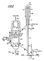
- the cracking apparatus comprises a riser cracking zone 4, and a catalyst disengaging and stripping zone 14, 48 adjacent to a two stage catalyst regeneration vessel 20 comprising two regeneration zones or beds 22, 34 located one above the other so that the flue gas products of the bottom bed 34 can pass upwardly into the bottom portion of the upper bed 22.
- reduced crude feed is charged to the riser cracking zone 4 via conduits 1 and 6 in admixture with one or more of steam (STM) naphtha and water via conduits 5 and 3.
- STM steam
- the steam, naphtha and water act as diluent materials, temperature adjustment materials, velocity providing materials, feed partial pressure reducing materials and a combination thereof to assure intimate rapid atomized and vaporised contact of the reduced crude feed with charged finely divided fluidizable catalyst particles fed from the regeneration vessel via line 44 to provide an upwardly flowing suspension at a temperature of at least about 510°C (950°F) and sufficiently elevated to provide a riser outlet temperature in the range of 510°C to 566°C (950°F to 1050°F).
- the upwardly flowing suspension in rider 4 is at a velocity to provide a hydrocarbon residence time within the range of 0.5 to 4 seconds and more usually in the range of 1 to 2 seconds.
- a short residence time may also be provided by alternatively charging the reduced crude feed through additional inlet conduits 2 and 7 located above the riser bottom.
- the steam, naphtha or other light hydrocarbons introduced to the riser bottom initially fluidize the catalyst charged to the riser via conduit 44 before contact with the reduced crude fed through the conduit 2 or 7.
- Catalyst bed 22 comprises the first stage of regeneration in accordance with the process of this invention.
- flue gas from the lower of the two catalyst beds 34 passes upwardly through apertures 29 in baffle plates 28 separating the two sections of the regeneration vessel and directly into the upper of the two catalyst regeneration beds 22.
- baffle plates 28 be of a porous construction or that the flue gases from the lower bed pass into the plenum chamber 26 for distribution with the regeneration gas and steam via the distributor 27, rather than directly into the bed 22.
- the flue gases from the lower bed may be passed through external cyclones for the removal of catalyst fines before passing to the bottom of the bed 22, in admixture with steam.
- the catalyst particles in the dense fluidised bed 22 are partially regenerated by contact with the mixture comprising the oxygen-containing regeneration gas and steam fed via lines 24 and 25 and the flue gases obtained from the lower bed 34. Partial regeneration of the catalyst in bed 22 is accomplished under steam reforming conditions at temperatures within the range 677°C to 815°C (1250°F to 1500°F). Flue gas products of regeneration pass through cyclone separator 30 before being withdrawn by conduit 32 for use as desired.
- the partially regenerated catalyst from bed 22 then passes to suitable withdrawal wells communicating with standpipes 36 and 40 for passage to the lower bed 34 with optional heating or cooling of the catalyst in standpipe 36 in a heat exchanger 38.
- regeneration of the catalyst is completed to provide a residual carbon content less than 0.1 wt % and preferably no more than 0.05 wt % by further contact with oxygen containing regeneration gas (REG) such as air or oxygen fed via conduit 42 optionally in combination with C0 2 fed via line 46.
- oxygen containing regeneration gas such as air or oxygen fed via conduit 42 optionally in combination with C0 2 fed via line 46.
- residual carbonaceous material is removed without exceeding a temperature of 815°C (1500°F) and preferably without exceeding a temperature of 760°C (1400°F).
- the transfer of catalyst from upper bed 22 to lower bed 34 may also be accomplished by one or more internal standpipes rather than by the external standpipes shown.
- the catalyst regenerated to a desired low level of residual carbon by the combination operation above discussed and at a desired elevated temperature is passed from catalyst bed 34 by standpipe 44 to a lower portion of riser 4 for re-use in the system as above described.
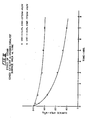
- FIG. II a graph directed to presenting data directed to carbon removal with steam from a GRZ-1 cracking catalyst (commercially available catalyst from W. R. Grace & Co.-Davidson Chemical Division) which had been coke with Arabian Light Reduced Crude.
- the graph shows that the reaction of steam to remove coke or carbonaceous material is relatively just for significant amounts of coke removal within a time span commensurate with that obtainable in a dense fluid catalyst bed regeneration operation.
- a catalyst comprising about 5.8 wt % carbon on catalyst is reduced to a residual carbon level of about 1.0 wt % when contacted with 787°C (1450°F) steam for 2 hours.
- coke removal is achievable with steam at temperatures of about 760°C (1400°F) to form CO and hydrogen which are combustible with added oxygen to generate needed endothermic heat.
- Figures III and IV show the effect of 787°C (1450°F) steam on a coked and uncoked GRZ-1 catalyst with respect to surface area and zeolite intensity.
- Zeolite intensity is identified with the active zeolite component or the catalyst, the greater the intensity, the more of the active crystalline zeolite component.
- the graphical data of Figures 3 and 4 show that steaming of the uncoked catalyst gave a much larger drop in surface area and zeolite intensity than obtained when contacting a coked catalyst with high temperature steam.
- the coke on the catalyst guards the deactivation of the catalyst against high temperature steam. This finding is used to advantage in pursuit of the concepts of this invention which is directed to reducing the temperature of regeneration of catalysts used in reduced crude cracking.
- Catalysts so used are known to accumulate large amounts of carbonaceous material attributable in substantial measure to the Conradson carbon level of the feed being processed and such high levels of deposited carbonaceous materials are instrumental in causing high temperatures to be encountered by burning removal thereof with oxygen containing gas such as air in the absence of extreme caution, head dissipation and restrict temperature sequential burning in a plurality of regeneration zones, all of which techniques are less than desirable.
- the regeneration combination of this invention is not only a unique approach to the removal of relatively large amounts of carbonaceous deposits but so also is the amount of carbonaceous material to be removed by burning with oxygen containing gas sufficiently reduced to permit maintaining desired temperature restrictions below 760°C (1400°F) and more preferably at the lowest temperature conditions promoting extended catalyst life and usage.
- oxygen containing gas sufficiently reduced to permit maintaining desired temperature restrictions below 760°C (1400°F) and more preferably at the lowest temperature conditions promoting extended catalyst life and usage.
- the regeneration concept of sequence of performance permits the processing of higher Conradson carbon feeds than previously considered possible at relatively low temperatures particularly suitable for achieving desired hydrocarbon conversion results.
Landscapes
- Chemical & Material Sciences (AREA)
- Oil, Petroleum & Natural Gas (AREA)
- Engineering & Computer Science (AREA)
- Chemical Kinetics & Catalysis (AREA)
- General Chemical & Material Sciences (AREA)
- Organic Chemistry (AREA)
- Crystallography & Structural Chemistry (AREA)
- Catalysts (AREA)
- Production Of Liquid Hydrocarbon Mixture For Refining Petroleum (AREA)
Claims (9)
Applications Claiming Priority (2)
| Application Number | Priority Date | Filing Date | Title |
|---|---|---|---|
| US36986082A | 1982-04-19 | 1982-04-19 | |
| US369860 | 1982-04-19 |
Publications (2)
| Publication Number | Publication Date |
|---|---|
| EP0092065A1 EP0092065A1 (de) | 1983-10-26 |
| EP0092065B1 true EP0092065B1 (de) | 1986-07-23 |
Family
ID=23457219
Family Applications (1)
| Application Number | Title | Priority Date | Filing Date |
|---|---|---|---|
| EP19830102928 Expired EP0092065B1 (de) | 1982-04-19 | 1983-03-24 | Regeneration eines Katalysators, der bei der Konversion carbo-metallischer Rückstandsöle verwendet worden ist |
Country Status (3)
| Country | Link |
|---|---|
| EP (1) | EP0092065B1 (de) |
| CA (1) | CA1183826A (de) |
| DE (1) | DE3364626D1 (de) |
Families Citing this family (15)
| Publication number | Priority date | Publication date | Assignee | Title |
|---|---|---|---|---|
| CA1242985A (en) * | 1984-02-08 | 1988-10-11 | William P. Hegarty | Method for controlling fluidized catalytic cracker regenerator temperature and velocity with carbon dioxide |
| FR2625748B1 (fr) * | 1988-01-08 | 1992-04-24 | Inst Francais Du Petrole | Utilisation d'un catalyseur contenant une zeolithe de la famille erionite dans un procede de craquage comportant au moins une zone de regeneration |
| EP0332536B1 (de) * | 1988-03-09 | 1992-07-29 | Total Raffinage Distribution S.A. | Verfahren und Vorrichtung zum Regenerieren eines Katalysators in einem Fliessbett |
| FR2628342A1 (fr) * | 1988-03-09 | 1989-09-15 | Total France | Procede et dispositif de regeneration en lit fluidise d'un catalyseur |
| FR2705142B1 (fr) * | 1993-05-10 | 1995-10-27 | Inst Francais Du Petrole | Procede de regulation du niveau thermique d'un solide dans un echangeur de chaleur presentant des nappes cylindriques de tubes. |
| DE10113041A1 (de) * | 2001-03-17 | 2002-09-26 | Linde Ag | Verfahren zur Gewinnung von Kohlenwasserstoffprodukten durch thermische Dampfspaltung und nachfolgende katalytische Behandlung |
| DE10209563B4 (de) * | 2002-03-04 | 2008-02-14 | Denise Kirsch | Schmuckring und Schmuckringbausatz |
| JP2009541538A (ja) * | 2006-06-22 | 2009-11-26 | シエル・インターナシヨネイル・リサーチ・マーチヤツピイ・ベー・ウイ | 無機塩回収による全生成物の製造用装置及び方法 |
| EP2214819A2 (de) * | 2007-11-16 | 2010-08-11 | ExxonMobil Chemical Patents Inc. | Katalysatorwiederherstellungsverfahren |
| US7935245B2 (en) | 2007-12-21 | 2011-05-03 | Uop Llc | System and method of increasing synthesis gas yield in a fluid catalytic cracking unit |
| US7699975B2 (en) | 2007-12-21 | 2010-04-20 | Uop Llc | Method and system of heating a fluid catalytic cracking unit for overall CO2 reduction |
| US7932204B2 (en) | 2007-12-21 | 2011-04-26 | Uop Llc | Method of regenerating catalyst in a fluidized catalytic cracking unit |
| US7811446B2 (en) | 2007-12-21 | 2010-10-12 | Uop Llc | Method of recovering energy from a fluid catalytic cracking unit for overall carbon dioxide reduction |
| US7767075B2 (en) | 2007-12-21 | 2010-08-03 | Uop Llc | System and method of producing heat in a fluid catalytic cracking unit |
| US7699974B2 (en) | 2007-12-21 | 2010-04-20 | Uop Llc | Method and system of heating a fluid catalytic cracking unit having a regenerator and a reactor |
Family Cites Families (6)
| Publication number | Priority date | Publication date | Assignee | Title |
|---|---|---|---|---|
| US4056486A (en) * | 1976-05-07 | 1977-11-01 | Texaco Inc. | Fluidized catalytic cracking regeneration process |
| US4062759A (en) * | 1976-05-07 | 1977-12-13 | Texaco Inc. | Fluidized catalytic cracking regeneration process |
| GB2001545B (en) * | 1977-07-28 | 1982-04-15 | Ici Ltd | Hydrocarbon processing |
| GB1569467A (en) * | 1977-11-09 | 1980-06-18 | Texaco Development Corp | Fluidized catalytic cracking regeneration process |
| US4274942A (en) * | 1979-04-04 | 1981-06-23 | Engelhard Minerals & Chemicals Corporation | Control of emissions in FCC regenerator flue gas |
| US4336160A (en) * | 1980-07-15 | 1982-06-22 | Dean Robert R | Method and apparatus for cracking residual oils |
-
1983
- 1983-03-24 EP EP19830102928 patent/EP0092065B1/de not_active Expired
- 1983-03-24 DE DE8383102928T patent/DE3364626D1/de not_active Expired
- 1983-03-29 CA CA000424732A patent/CA1183826A/en not_active Expired
Also Published As
| Publication number | Publication date |
|---|---|
| CA1183826A (en) | 1985-03-12 |
| DE3364626D1 (en) | 1986-08-28 |
| EP0092065A1 (de) | 1983-10-26 |
Similar Documents
| Publication | Publication Date | Title |
|---|---|---|
| EP0106052B1 (de) | Entmetallisierung und Entkarbonisierung schwerer Rückstandsöl-Einsatzprodukte | |
| US4875994A (en) | Process and apparatus for catalytic cracking of residual oils | |
| CA1156591A (en) | Method for two stage catalyst regeneration | |
| EP2161322B1 (de) | Rückgewinnung des Katalysators aus einem leichte Olefine enthaltenden FCC Abgasstrom | |
| EP1408100B1 (de) | Katalysator Regeneration mit Mittelrohr | |
| EP0171460B1 (de) | Verfahren zur katalytischen Spaltung von Residualölen mit Trockengas als Auftriebgas in einem Steigrohrreaktor | |
| EP0092065B1 (de) | Regeneration eines Katalysators, der bei der Konversion carbo-metallischer Rückstandsöle verwendet worden ist | |
| EP0074501B1 (de) | Verfahren und Katalysator für die Umwandlung von Koksvorläufer und Schwermetalle enthaltenden Ölen | |
| US4584090A (en) | Method and apparatus for catalytically converting fractions of crude oil boiling above gasoline | |
| US4457833A (en) | Process and catalyst for the conversion of carbo-metallic containing oils | |
| JPS61501454A (ja) | 貴重な液体生成物が高収率で得られる重質炭化水素のクラツキング | |
| EP0134924B1 (de) | Zugabe von Wasser zur Regenerationsluft | |
| US4894141A (en) | Combination process for upgrading residual oils | |
| AU648853B2 (en) | Heavy oil catalytic cracking process and apparatus | |
| US4430201A (en) | Regeneration of fluidizable catalyst | |
| US5362380A (en) | Fluid catalytic cracking process yielding hydrogen | |
| US4428822A (en) | Fluid catalytic cracking | |
| EP0490453A1 (de) | Verfahren und Apparat zur Beseitigung von Kohlenstoffmaterialien von Feststoffteilchen | |
| US4915820A (en) | Removal of coke and metals from carbo-metallic oils | |
| CA1183825A (en) | Regeneration of catalyst used in the conversion of carbo-metallic containing residual oils | |
| US20040140246A1 (en) | Process for upgrading fcc product with additional reactor | |
| EP0236055A2 (de) | Verfahren zur Behandlung von Kohlenwasserstoffen | |
| EP0439509A4 (en) | Resid cracking process and apparatus | |
| US4693809A (en) | Hydrocarbon conversion process | |
| EP0234924A2 (de) | Verfahren zur Behandlung von Kohlenwasserstoffen |
Legal Events
| Date | Code | Title | Description |
|---|---|---|---|
| PUAI | Public reference made under article 153(3) epc to a published international application that has entered the european phase |
Free format text: ORIGINAL CODE: 0009012 |
|
| AK | Designated contracting states |
Designated state(s): AT BE DE FR GB IT NL SE |
|
| 17P | Request for examination filed |
Effective date: 19840425 |
|
| GRAA | (expected) grant |
Free format text: ORIGINAL CODE: 0009210 |
|
| AK | Designated contracting states |
Kind code of ref document: B1 Designated state(s): DE FR GB NL |
|
| REF | Corresponds to: |
Ref document number: 3364626 Country of ref document: DE Date of ref document: 19860828 |
|
| ET | Fr: translation filed | ||
| PLBE | No opposition filed within time limit |
Free format text: ORIGINAL CODE: 0009261 |
|
| STAA | Information on the status of an ep patent application or granted ep patent |
Free format text: STATUS: NO OPPOSITION FILED WITHIN TIME LIMIT |
|
| 26N | No opposition filed | ||
| PG25 | Lapsed in a contracting state [announced via postgrant information from national office to epo] |
Ref country code: DE Effective date: 19881201 |
|
| PGFP | Annual fee paid to national office [announced via postgrant information from national office to epo] |
Ref country code: FR Payment date: 19901218 Year of fee payment: 9 |
|
| PGFP | Annual fee paid to national office [announced via postgrant information from national office to epo] |
Ref country code: GB Payment date: 19901224 Year of fee payment: 9 |
|
| PGFP | Annual fee paid to national office [announced via postgrant information from national office to epo] |
Ref country code: NL Payment date: 19910331 Year of fee payment: 9 |
|
| PG25 | Lapsed in a contracting state [announced via postgrant information from national office to epo] |
Ref country code: GB Effective date: 19920324 |
|
| PG25 | Lapsed in a contracting state [announced via postgrant information from national office to epo] |
Ref country code: NL Effective date: 19921001 |
|
| NLV4 | Nl: lapsed or anulled due to non-payment of the annual fee | ||
| GBPC | Gb: european patent ceased through non-payment of renewal fee | ||
| PG25 | Lapsed in a contracting state [announced via postgrant information from national office to epo] |
Ref country code: FR Effective date: 19921130 |
|
| REG | Reference to a national code |
Ref country code: FR Ref legal event code: ST |