EP0092066A1 - Suspension de roue de véhicule - Google Patents
Suspension de roue de véhicule Download PDFInfo
- Publication number
- EP0092066A1 EP0092066A1 EP83102966A EP83102966A EP0092066A1 EP 0092066 A1 EP0092066 A1 EP 0092066A1 EP 83102966 A EP83102966 A EP 83102966A EP 83102966 A EP83102966 A EP 83102966A EP 0092066 A1 EP0092066 A1 EP 0092066A1
- Authority
- EP
- European Patent Office
- Prior art keywords
- axis
- suspension
- seat
- block
- wheel
- Prior art date
- Legal status (The legal status is an assumption and is not a legal conclusion. Google has not performed a legal analysis and makes no representation as to the accuracy of the status listed.)
- Granted
Links
Images

Classifications
-
- B—PERFORMING OPERATIONS; TRANSPORTING
- B60—VEHICLES IN GENERAL
- B60G—VEHICLE SUSPENSION ARRANGEMENTS
- B60G15/00—Resilient suspensions characterised by arrangement, location or type of combined spring and vibration damper, e.g. telescopic type
- B60G15/02—Resilient suspensions characterised by arrangement, location or type of combined spring and vibration damper, e.g. telescopic type having mechanical spring
- B60G15/06—Resilient suspensions characterised by arrangement, location or type of combined spring and vibration damper, e.g. telescopic type having mechanical spring and fluid damper
- B60G15/067—Resilient suspensions characterised by arrangement, location or type of combined spring and vibration damper, e.g. telescopic type having mechanical spring and fluid damper characterised by the mounting on the vehicle body or chassis of the spring and damper unit
- B60G15/068—Resilient suspensions characterised by arrangement, location or type of combined spring and vibration damper, e.g. telescopic type having mechanical spring and fluid damper characterised by the mounting on the vehicle body or chassis of the spring and damper unit specially adapted for MacPherson strut-type suspension
-
- B—PERFORMING OPERATIONS; TRANSPORTING
- B62—LAND VEHICLES FOR TRAVELLING OTHERWISE THAN ON RAILS
- B62D—MOTOR VEHICLES; TRAILERS
- B62D17/00—Means on vehicles for adjusting camber, castor, or toe-in
-
- B—PERFORMING OPERATIONS; TRANSPORTING
- B60—VEHICLES IN GENERAL
- B60G—VEHICLE SUSPENSION ARRANGEMENTS
- B60G2200/00—Indexing codes relating to suspension types
- B60G2200/40—Indexing codes relating to the wheels in the suspensions
- B60G2200/46—Indexing codes relating to the wheels in the suspensions camber angle
-
- B—PERFORMING OPERATIONS; TRANSPORTING
- B60—VEHICLES IN GENERAL
- B60G—VEHICLE SUSPENSION ARRANGEMENTS
- B60G2202/00—Indexing codes relating to the type of spring, damper or actuator
- B60G2202/30—Spring/Damper and/or actuator Units
- B60G2202/31—Spring/Damper and/or actuator Units with the spring arranged around the damper, e.g. MacPherson strut
- B60G2202/312—The spring being a wound spring
-
- B—PERFORMING OPERATIONS; TRANSPORTING
- B60—VEHICLES IN GENERAL
- B60G—VEHICLE SUSPENSION ARRANGEMENTS
- B60G2204/00—Indexing codes related to suspensions per se or to auxiliary parts
- B60G2204/10—Mounting of suspension elements
- B60G2204/12—Mounting of springs or dampers
- B60G2204/124—Mounting of coil springs
-
- B—PERFORMING OPERATIONS; TRANSPORTING
- B60—VEHICLES IN GENERAL
- B60G—VEHICLE SUSPENSION ARRANGEMENTS
- B60G2204/00—Indexing codes related to suspensions per se or to auxiliary parts
- B60G2204/10—Mounting of suspension elements
- B60G2204/12—Mounting of springs or dampers
- B60G2204/128—Damper mount on vehicle body or chassis
-
- B—PERFORMING OPERATIONS; TRANSPORTING
- B60—VEHICLES IN GENERAL
- B60G—VEHICLE SUSPENSION ARRANGEMENTS
- B60G2204/00—Indexing codes related to suspensions per se or to auxiliary parts
- B60G2204/40—Auxiliary suspension parts; Adjustment of suspensions
- B60G2204/41—Elastic mounts, e.g. bushings
-
- B—PERFORMING OPERATIONS; TRANSPORTING
- B60—VEHICLES IN GENERAL
- B60G—VEHICLE SUSPENSION ARRANGEMENTS
- B60G2204/00—Indexing codes related to suspensions per se or to auxiliary parts
- B60G2204/40—Auxiliary suspension parts; Adjustment of suspensions
- B60G2204/43—Fittings, brackets or knuckles
-
- B—PERFORMING OPERATIONS; TRANSPORTING
- B60—VEHICLES IN GENERAL
- B60G—VEHICLE SUSPENSION ARRANGEMENTS
- B60G2204/00—Indexing codes related to suspensions per se or to auxiliary parts
- B60G2204/40—Auxiliary suspension parts; Adjustment of suspensions
- B60G2204/44—Centering or positioning means
-
- B—PERFORMING OPERATIONS; TRANSPORTING
- B60—VEHICLES IN GENERAL
- B60G—VEHICLE SUSPENSION ARRANGEMENTS
- B60G2204/00—Indexing codes related to suspensions per se or to auxiliary parts
- B60G2204/61—Adjustable during maintenance
Definitions
- This invention relates to a vehicle wheel suspension, and more specifically to a suspension of the so-called independent wheel type in which the wheel is supported by a mounting connected to the vehicle body by means of a swinging bar, a torsion bar which connects together the pair of front suspensions and the pair of rear suspensions, and a shock absorber fixed to the vehicle body by means of an elastic block.
- angle of incidence signifies the angle formed between the projection of the shock absorber axis in a plane lateral to the vehicle and parallel to the plane in which the wheel lies, and the vertical to the ground passing through the axis of rotation of the wheel
- offset signifies the segment which is cut in the ground plane by the projection in a plane lateral to the vehicle and parallel to the plane in which the wheel lies, of the axis joining the elastic block to the ball joint connecting the swinging bar to the suspension mounting, and which lies between the projection itself and the vertical to the ground passing through the axis of rotation of the wheel.
- the methods used consist generally either of replacing the elastic suspension block with another block of different form so as to obtain angles of incidence and thus offsets of a different extent, or of applying means to enable the point of connection of the elastic block to the vehicle body to be moved, so as to again obtain a variation in the angle of incidence.
- the object of the present invention is to provide a vehicle wheel suspension free from the described drawbacks, which is able to allow the suspension offset to be simply and quickly changed, and is of simple and economical construction.
- a vehicle suspension of the type comprising a mounting which is arranged to rotatably house the hub of said wheel and is supported by a swinging bar connected to the body of said vehicle and by a shock absorber comprising a casing and a rod, this latter being connected to the vehicle body by means of an elastic block comprising a bearing keyed on to said rod, an outer housing arranged for fixing to a body element, and at least one deformable elastic sleeve disposed between said bearing and said housing, characterised in that said body element is curved, and comprises a substantially oval seat for said elastic block, in which this latter is mobile between at least two predetermined positions, said outer housing being provided, for its fixing to the body, with a flange having a curved surface and arranged to cooperate with said body element.
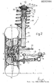
- the reference numeral 1 indicates overall a suspension for a wheel 2 of a vehicle, not shown.
- the suspension 1 is of the so-called “independent wheel” type and is specifically a MacPherson front suspension.
- the suspension 1 comprises a mounting 3 to rotatably house the wheel hub 4 provided with a brake drum 5, and a shock absorber 6 and swinging bar 7 which are arranged to support the mounting 3 by connecting it to the body 8 of said vehicle.
- the swinging bar 7 is connected to the mounting 3 by means of a ball joint 9, and is connected to the body 8 by means of a known hinge, not shown.
- the swinging bar 7 is also connected to a torsion bar-10, which is connected to the body 8 by means of a support 11 and to the swinging bar 7 by means of a rod 12.
- the purpose of the torsion bar 10 is, inter alia, to connect together the two front suspensions and the two rear suspensions respectively, in order to ensure their uniform behaviour.
- the shock absorber 6 is connected to the mounting 3 by means of a lower socket connector 13 rigidly connected to said mounting 3, and is connected at its top to the body 8, namely to a curved body element 14 of substantially spherical form, by means of an elastic block 15 housed in a seat 16 in the body element 14.
- the shock absorber 6 is also provided with a spiral spring 18 mounted about it between a disc 19 connected to the casing 20 of the shock absorber 6 and a disc 21 connected to the shock absorber rod 22 which is slidable in the casing 20. This latter is fixed to the connector 13, whereas the rod 22 is connected to the block 15.
- the mounting 3 is also provided with an arm 23 connected by an articulated joint 24 to the track rod 25 of any known steering device, not shown for simplicity.
- the block 15 comprises a rolling bearing 26 keyed on to the rod 22, an outer housing 27, preferably of sheet metal, arranged for releasable fixing to the body element 14, and at least one deformable elastic sleeve 28, preferably of rubber construction, disposed between the bearing 26 and housing 27.
- the housing 27 is provided with a connection flange 29 which is also curved, having a substantially spherical surface 30 facing the body element 14, and arranged to cooperate with this latter.
- the flange 29 is of substantially pentagonal shape when viewed in plan, and the seat 16 is substantially oval.
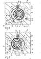
- the block 15 is housed in the seat 16 slackly so as to be mobile therein between at least two predetermined positions shown in Figures 3 and 4 respectively.
- the elastic block 15 can be fixed to the body element 14 either in the position of Figure 3 or in the position of Figure 4 by any removable fixing means of known type.
- the block 15 is fixed to the element 14 by screws which lock the flange 29 against said element 14.'
- a first screw 31 is disposed laterally to the seat 16 to correspond with the transverse axis of symmetry 32 of this latter, and a pair of screws 33 disposed in slots 34 provided in the flange 29 can selectively engage a first bore 35 or a second bore 36 of two pairs 37 of bores provided in the element 14 laterally to the seat 16, on the opposite side to the screw 31.
- the block 15 is housed in the seat 16 eccentrically to the axis of symmetry 32, at opposite ends 38 or 39 of the seat 16, so as to assume two symmetrical positions about the axis 32, in which the axis of the block 15 is distant from the axis 32 by an identical distance e.
- the geometry of the suspension 1 is also such that in a plane X-X lateral to the vehicle and parallel (or coinciding) with the plane in which the wheel 2 lies, the projection of the axis of the shock absorber 6 coincides with the projection of an axis 40 joining the block 15 to the ball joint 9, said projection intersecting the axis of rotation of the wheel 2 and being oblique to the vertical to the ground which passes through the axis of rotation of the wheel 2, in such a manner as to define where it cuts the ground plane a segment b of determined length lying between said projection and said vertical, and constituting the "offset" of the suspension 1.
- the angle lying between the projection of the axis 40 and said vertical coincides with the angle of incidence of the axis of the shock absorber.
- the radius of spherical curvature of the body element 14 and flange 29 has its centre lying substantially on the axis of rotation of the wheel 2.
- the element 14 and flange 29 could be other than spherical, and instead have any curved profile of which the focus is disposed substantially on the axis of the hub 4.
- the angle of incidence ⁇ of the axis of the shock absorber 6 with respect to the ground is also changed during the movement of the block 15 in the seat 16, so as to vary the length of the segment b.
- the shock absorber 6 and the entire mounting 3 rotate about the axis of the wheel 2 parallel to the plane X-X, and consequently the ball joint 9 approaches (or withdraws from) the vertical to the ground which passes through the wheel axis.
- the described suspension 1 has the advantage of allowing the shock absorber 6 to always remain coaxial with the block 15 and relative bearing 26, whatever the angle of incidence ⁇ and the consequent offset b. Consequently, no reaction stresses occur in the block 15 as a consequence of its movement in varying the segment b. Furthermore, the invention provides a suspension which is of simple and economical construction, which uses a single type of elastic block, and which can be adjusted simply and rapidly by merely rotating the block in its seat in the vehicle body, without having to disassemble the suspension itself.
Landscapes
- Engineering & Computer Science (AREA)
- Mechanical Engineering (AREA)
- Chemical & Material Sciences (AREA)
- Combustion & Propulsion (AREA)
- Transportation (AREA)
- Vehicle Body Suspensions (AREA)
Applications Claiming Priority (2)
| Application Number | Priority Date | Filing Date | Title |
|---|---|---|---|
| IT6752782 | 1982-04-21 | ||
| IT67527/82A IT1155316B (it) | 1982-04-21 | 1982-04-21 | Sospensione per una ruota di un veicolo |
Publications (2)
| Publication Number | Publication Date |
|---|---|
| EP0092066A1 true EP0092066A1 (fr) | 1983-10-26 |
| EP0092066B1 EP0092066B1 (fr) | 1985-12-11 |
Family
ID=11303162
Family Applications (1)
| Application Number | Title | Priority Date | Filing Date |
|---|---|---|---|
| EP83102966A Expired EP0092066B1 (fr) | 1982-04-21 | 1983-03-24 | Suspension de roue de véhicule |
Country Status (4)
| Country | Link |
|---|---|
| EP (1) | EP0092066B1 (fr) |
| DE (1) | DE3361467D1 (fr) |
| ES (1) | ES521669A0 (fr) |
| IT (1) | IT1155316B (fr) |
Cited By (15)
| Publication number | Priority date | Publication date | Assignee | Title |
|---|---|---|---|---|
| GB2143784A (en) * | 1983-06-24 | 1985-02-20 | Fischer Ag Georg | Vehicle suspension shock absorber leg connection |
| EP0265059A1 (fr) * | 1986-09-10 | 1988-04-27 | Arindol Pty. Limited | Système de suspension de véhicule |
| EP0320608A3 (en) * | 1987-12-09 | 1989-07-05 | Woco Franz-Josef Wolf & Co. | Spring for a damper |
| EP0326710A3 (en) * | 1988-02-04 | 1989-11-15 | Dr.Ing.H.C. F. Porsche Aktiengesellschaft | Shiftable resilient support bearing for a damper |
| WO1993000244A1 (fr) * | 1991-06-21 | 1993-01-07 | Kevin Joseph Mcintyre | Elements de reglage de suspension d'automobile |
| EP0780250A3 (fr) * | 1995-12-19 | 1998-05-06 | COMPAGNIE GENERALE DES ETABLISSEMENTS MICHELIN-MICHELIN & CIE | Réglage précis d'une jambe de force de suspension MacPherson: moyens de réglage sur la jambe et banc de mesure |
| FR2766449A1 (fr) * | 1996-07-25 | 1999-01-29 | Daimler Benz Ag | Dispositif de reglage de la chasse d'une roue directrice braquee au moyen d'organes de direction articules, notamment pour vehicules automobiles |
| FR2768659A1 (fr) * | 1997-09-24 | 1999-03-26 | Caoutchouc Manuf Plastique | Dispositif de suspension de roue de vehicule |
| WO1999015802A1 (fr) * | 1997-09-24 | 1999-04-01 | Michelin Avs | Moyen d'articulation entre deux pieces de liaison et suspension de roue de vehicule automobile equipe d'un tel moyen |
| US5931485A (en) * | 1996-07-25 | 1999-08-03 | Daimler Benz Ag | Support arrangement for a steered vehicle wheel |
| EP0985565A1 (fr) * | 1998-09-14 | 2000-03-15 | Peugeot Citroen Automobiles SA | Dispositif de fixation supérieure d'un amortisseur de suspension d'une roue avant d'un véhicule automobile |
| US6247688B1 (en) | 1998-08-10 | 2001-06-19 | Michelin Avs | Vehicle wheel suspension device |
| EP2186661A1 (fr) * | 2008-11-14 | 2010-05-19 | Audi AG | Appui modifiable d'un ressort à boudin de compression ou analogue pour un véhicule automobile |
| US20120242055A1 (en) * | 2011-03-25 | 2012-09-27 | GM Global Technology Operations LLC | Bearing, vehicle, and method for assembling a vehicle |
| DE102013011578A1 (de) | 2013-07-11 | 2015-01-15 | Audi Ag | Dämpferlager |
Families Citing this family (1)
| Publication number | Priority date | Publication date | Assignee | Title |
|---|---|---|---|---|
| DE3730176A1 (de) * | 1987-09-09 | 1989-03-30 | Bayerische Motoren Werke Ag | Verstelleinrichtung fuer das gelenk eines lenkers einer radaufhaengung |
Citations (9)
| Publication number | Priority date | Publication date | Assignee | Title |
|---|---|---|---|---|
| US2065071A (en) * | 1934-07-12 | 1936-12-22 | Chrysler Corp | Vehicle wheel suspension |
| FR821418A (fr) * | 1936-05-05 | 1937-12-04 | Audi Ag | Suspension élastique pour voitures automobiles |
| DE1278261B (de) * | 1963-11-30 | 1968-09-19 | Daimler Benz Ag | Vorrichtung zur Nachlaufeinstellung eines mittels Lenker gefuehrten gelenkten Rades,insbesondere fuer Kraftfahrzeuge |
| DE2520580A1 (de) * | 1975-05-09 | 1976-11-18 | Audi Nsu Auto Union Ag | Widerlager fuer die feder und den stossdaempfer einer geradfuehrung fuer unabhaengig aufgehaengte raeder von kraftfahrzeugen |
| FR2405150A1 (fr) * | 1977-10-08 | 1979-05-04 | Volkswagenwerk Ag | Montage d'une jambe de suspension ou d'un amortisseur sur la carrosserie d'un vehicule |
| US4175771A (en) * | 1978-07-27 | 1979-11-27 | General Motors Corporation | Resilient mounting means for MacPherson strut |
| US4213631A (en) * | 1978-06-22 | 1980-07-22 | Wilkerson Edward D | Vehicle wheel alignment adjustment device |
| FR2452411A1 (fr) * | 1979-03-30 | 1980-10-24 | Audi Ag | Suspension de roue pour vehicules automobiles |
| US4372575A (en) * | 1981-02-09 | 1983-02-08 | General Motors Corporation | Vehicle strut type suspension with alignment adjustment |
-
1982
- 1982-04-21 IT IT67527/82A patent/IT1155316B/it active
-
1983
- 1983-03-24 EP EP83102966A patent/EP0092066B1/fr not_active Expired
- 1983-03-24 DE DE8383102966T patent/DE3361467D1/de not_active Expired
- 1983-04-20 ES ES521669A patent/ES521669A0/es active Granted
Patent Citations (9)
| Publication number | Priority date | Publication date | Assignee | Title |
|---|---|---|---|---|
| US2065071A (en) * | 1934-07-12 | 1936-12-22 | Chrysler Corp | Vehicle wheel suspension |
| FR821418A (fr) * | 1936-05-05 | 1937-12-04 | Audi Ag | Suspension élastique pour voitures automobiles |
| DE1278261B (de) * | 1963-11-30 | 1968-09-19 | Daimler Benz Ag | Vorrichtung zur Nachlaufeinstellung eines mittels Lenker gefuehrten gelenkten Rades,insbesondere fuer Kraftfahrzeuge |
| DE2520580A1 (de) * | 1975-05-09 | 1976-11-18 | Audi Nsu Auto Union Ag | Widerlager fuer die feder und den stossdaempfer einer geradfuehrung fuer unabhaengig aufgehaengte raeder von kraftfahrzeugen |
| FR2405150A1 (fr) * | 1977-10-08 | 1979-05-04 | Volkswagenwerk Ag | Montage d'une jambe de suspension ou d'un amortisseur sur la carrosserie d'un vehicule |
| US4213631A (en) * | 1978-06-22 | 1980-07-22 | Wilkerson Edward D | Vehicle wheel alignment adjustment device |
| US4175771A (en) * | 1978-07-27 | 1979-11-27 | General Motors Corporation | Resilient mounting means for MacPherson strut |
| FR2452411A1 (fr) * | 1979-03-30 | 1980-10-24 | Audi Ag | Suspension de roue pour vehicules automobiles |
| US4372575A (en) * | 1981-02-09 | 1983-02-08 | General Motors Corporation | Vehicle strut type suspension with alignment adjustment |
Non-Patent Citations (1)
| Title |
|---|
| PATENTS ABSTRACTS OF JAPAN, vol. 6, no. 45(M-118)(923), 20th March 1982 & JP - A - 56 160 207 (NISSAN JIDOSHA K.K.) 09-12-1981 * |
Cited By (22)
| Publication number | Priority date | Publication date | Assignee | Title |
|---|---|---|---|---|
| GB2143784A (en) * | 1983-06-24 | 1985-02-20 | Fischer Ag Georg | Vehicle suspension shock absorber leg connection |
| EP0265059A1 (fr) * | 1986-09-10 | 1988-04-27 | Arindol Pty. Limited | Système de suspension de véhicule |
| EP0320608A3 (en) * | 1987-12-09 | 1989-07-05 | Woco Franz-Josef Wolf & Co. | Spring for a damper |
| EP0326710A3 (en) * | 1988-02-04 | 1989-11-15 | Dr.Ing.H.C. F. Porsche Aktiengesellschaft | Shiftable resilient support bearing for a damper |
| WO1993000244A1 (fr) * | 1991-06-21 | 1993-01-07 | Kevin Joseph Mcintyre | Elements de reglage de suspension d'automobile |
| EP0780250A3 (fr) * | 1995-12-19 | 1998-05-06 | COMPAGNIE GENERALE DES ETABLISSEMENTS MICHELIN-MICHELIN & CIE | Réglage précis d'une jambe de force de suspension MacPherson: moyens de réglage sur la jambe et banc de mesure |
| US6082720A (en) * | 1995-12-19 | 2000-07-04 | Compagnie Generale Des Etablissements Michelin - Michelin & Cie | Precise adjustment of MacPherson strut: adjustment means on the strut and measuring bench |
| US5947459A (en) * | 1995-12-19 | 1999-09-07 | Compagnie Generale des Etablissements Michelin--Michelin & Cie | Precise adjustment of a MacPherson strut: adjustment means on the strut and measuring bench |
| US5931485A (en) * | 1996-07-25 | 1999-08-03 | Daimler Benz Ag | Support arrangement for a steered vehicle wheel |
| FR2766449A1 (fr) * | 1996-07-25 | 1999-01-29 | Daimler Benz Ag | Dispositif de reglage de la chasse d'une roue directrice braquee au moyen d'organes de direction articules, notamment pour vehicules automobiles |
| WO1999015802A1 (fr) * | 1997-09-24 | 1999-04-01 | Michelin Avs | Moyen d'articulation entre deux pieces de liaison et suspension de roue de vehicule automobile equipe d'un tel moyen |
| FR2768659A1 (fr) * | 1997-09-24 | 1999-03-26 | Caoutchouc Manuf Plastique | Dispositif de suspension de roue de vehicule |
| WO1999015351A1 (fr) * | 1997-09-24 | 1999-04-01 | Michelin Avs | Dispositif de suspension de roue de vehicule |
| US6375205B1 (en) | 1997-09-24 | 2002-04-23 | Michelin Avs | Articulating means between two connecting parts and motor vehicle wheel suspension equipped therewith |
| US6247688B1 (en) | 1998-08-10 | 2001-06-19 | Michelin Avs | Vehicle wheel suspension device |
| EP0985565A1 (fr) * | 1998-09-14 | 2000-03-15 | Peugeot Citroen Automobiles SA | Dispositif de fixation supérieure d'un amortisseur de suspension d'une roue avant d'un véhicule automobile |
| FR2783204A1 (fr) * | 1998-09-14 | 2000-03-17 | Peugeot | Dispositif de fixation superieure d'un amortisseur de suspension d'une roue avant d'un vehicule automobile |
| EP2186661A1 (fr) * | 2008-11-14 | 2010-05-19 | Audi AG | Appui modifiable d'un ressort à boudin de compression ou analogue pour un véhicule automobile |
| US20120242055A1 (en) * | 2011-03-25 | 2012-09-27 | GM Global Technology Operations LLC | Bearing, vehicle, and method for assembling a vehicle |
| DE102011015011A1 (de) | 2011-03-25 | 2012-09-27 | GM Global Technology Operations LLC (n. d. Gesetzen des Staates Delaware) | Lager, Fahrzeug sowie Verfahren zum Montieren eines Fahrzeugs |
| DE102013011578A1 (de) | 2013-07-11 | 2015-01-15 | Audi Ag | Dämpferlager |
| DE102013011578B4 (de) | 2013-07-11 | 2022-01-27 | Audi Ag | Dämpferlager und Verfahren zur Bereitstellung unterschiedlicher Einstellungen von vordefinierten Fahrwerkscharakteristika mittels des Dämpferlagers |
Also Published As
| Publication number | Publication date |
|---|---|
| ES8404251A1 (es) | 1984-04-16 |
| IT1155316B (it) | 1987-01-28 |
| EP0092066B1 (fr) | 1985-12-11 |
| DE3361467D1 (en) | 1986-01-23 |
| IT8267527A0 (it) | 1982-04-21 |
| ES521669A0 (es) | 1984-04-16 |
| IT8267527A1 (it) | 1983-10-21 |
Similar Documents
| Publication | Publication Date | Title |
|---|---|---|
| EP0092066B1 (fr) | Suspension de roue de véhicule | |
| US4213631A (en) | Vehicle wheel alignment adjustment device | |
| US4194760A (en) | Wheel camber adjusting means for vehicles | |
| US6082720A (en) | Precise adjustment of MacPherson strut: adjustment means on the strut and measuring bench | |
| US4834412A (en) | Motorcycle front wheel suspension device | |
| EP0312649B1 (fr) | Suspension de véhicule | |
| EP0195538A2 (fr) | Suspension de roue de véhicule | |
| US4619465A (en) | Shim for adjusting camber | |
| EP0070025A2 (fr) | Suspension à bras tiré pour un vehicule automobile | |
| US2123087A (en) | Individual wheel suspension | |
| US4795187A (en) | King pin member for adjusting camber, and method | |
| US5938220A (en) | Pivot bushing for McPherson type suspension | |
| EP0236303A1 (fr) | Ameliorations apportees a la suspension avant d'une motocyclette | |
| MX9708003A (es) | Suspension de eje montado con resorte pivoteante. | |
| EP0323815A1 (fr) | Suspension arrière pour véhicules automobiles à roues indépendantes du type à quadrilatères transversaux | |
| CN105313960B (zh) | 用于车辆悬架的可调整前束曲线转向节和方法 | |
| CA1226879A (fr) | Suspension independante de roue arriere | |
| US20070040346A1 (en) | Equalizer for a suspension system | |
| US4856886A (en) | Outside rear-view mirror having a mechanically adjustable mirror glass for a vehicle | |
| CA1185424A (fr) | Dispositif de reglage des roues | |
| US4159186A (en) | Ball joint, particularly for use in motor vehicles | |
| US4117709A (en) | Camber adjusting tool | |
| US6276702B1 (en) | Wheel suspension assembly | |
| US3961804A (en) | Steering arm attachment adapter for steering stabilizer | |
| JPS58184327A (ja) | デイスクブレ−キカリパ |
Legal Events
| Date | Code | Title | Description |
|---|---|---|---|
| PUAI | Public reference made under article 153(3) epc to a published international application that has entered the european phase |
Free format text: ORIGINAL CODE: 0009012 |
|
| AK | Designated contracting states |
Designated state(s): DE FR GB SE |
|
| 17P | Request for examination filed |
Effective date: 19840227 |
|
| GRAA | (expected) grant |
Free format text: ORIGINAL CODE: 0009210 |
|
| AK | Designated contracting states |
Designated state(s): DE FR GB SE |
|
| ET | Fr: translation filed | ||
| REF | Corresponds to: |
Ref document number: 3361467 Country of ref document: DE Date of ref document: 19860123 |
|
| PLBE | No opposition filed within time limit |
Free format text: ORIGINAL CODE: 0009261 |
|
| STAA | Information on the status of an ep patent application or granted ep patent |
Free format text: STATUS: NO OPPOSITION FILED WITHIN TIME LIMIT |
|
| 26N | No opposition filed | ||
| PGFP | Annual fee paid to national office [announced via postgrant information from national office to epo] |
Ref country code: SE Payment date: 19930212 Year of fee payment: 11 |
|
| PGFP | Annual fee paid to national office [announced via postgrant information from national office to epo] |
Ref country code: GB Payment date: 19930319 Year of fee payment: 11 |
|
| PG25 | Lapsed in a contracting state [announced via postgrant information from national office to epo] |
Ref country code: GB Effective date: 19940324 |
|
| PG25 | Lapsed in a contracting state [announced via postgrant information from national office to epo] |
Ref country code: SE Free format text: LAPSE BECAUSE OF NON-PAYMENT OF DUE FEES Effective date: 19940325 |
|
| PGFP | Annual fee paid to national office [announced via postgrant information from national office to epo] |
Ref country code: DE Payment date: 19940406 Year of fee payment: 12 |
|
| GBPC | Gb: european patent ceased through non-payment of renewal fee |
Effective date: 19940324 |
|
| EUG | Se: european patent has lapsed |
Ref document number: 83102966.5 Effective date: 19941010 |
|
| PGFP | Annual fee paid to national office [announced via postgrant information from national office to epo] |
Ref country code: FR Payment date: 19950317 Year of fee payment: 13 |
|
| PG25 | Lapsed in a contracting state [announced via postgrant information from national office to epo] |
Ref country code: DE Effective date: 19951201 |
|
| PG25 | Lapsed in a contracting state [announced via postgrant information from national office to epo] |
Ref country code: FR Effective date: 19961129 |
|
| REG | Reference to a national code |
Ref country code: FR Ref legal event code: ST |