EP0092080A1 - Endoscope ultrasonique - Google Patents
Endoscope ultrasonique Download PDFInfo
- Publication number
- EP0092080A1 EP0092080A1 EP83103181A EP83103181A EP0092080A1 EP 0092080 A1 EP0092080 A1 EP 0092080A1 EP 83103181 A EP83103181 A EP 83103181A EP 83103181 A EP83103181 A EP 83103181A EP 0092080 A1 EP0092080 A1 EP 0092080A1
- Authority
- EP
- European Patent Office
- Prior art keywords
- ultrasound
- endoscope
- endoscope according
- probe
- tube
- Prior art date
- Legal status (The legal status is an assumption and is not a legal conclusion. Google has not performed a legal analysis and makes no representation as to the accuracy of the status listed.)
- Ceased
Links
- 238000002604 ultrasonography Methods 0.000 claims abstract description 56
- 239000000523 sample Substances 0.000 claims abstract description 45
- 238000002575 gastroscopy Methods 0.000 claims abstract description 5
- 210000002105 tongue Anatomy 0.000 claims description 9
- 229920002379 silicone rubber Polymers 0.000 claims description 4
- 239000004945 silicone rubber Substances 0.000 claims description 4
- 230000008878 coupling Effects 0.000 claims description 3
- 238000010168 coupling process Methods 0.000 claims description 3
- 238000005859 coupling reaction Methods 0.000 claims description 3
- 239000000853 adhesive Substances 0.000 claims description 2
- 230000001070 adhesive effect Effects 0.000 claims description 2
- 229920001971 elastomer Polymers 0.000 claims description 2
- 239000011810 insulating material Substances 0.000 claims description 2
- 229910001220 stainless steel Inorganic materials 0.000 claims description 2
- 239000010935 stainless steel Substances 0.000 claims description 2
- 239000000463 material Substances 0.000 claims 1
- 230000013011 mating Effects 0.000 claims 1
- 230000005855 radiation Effects 0.000 claims 1
- 239000000654 additive Substances 0.000 description 5
- 230000000996 additive effect Effects 0.000 description 5
- 239000002184 metal Substances 0.000 description 3
- 229910052751 metal Inorganic materials 0.000 description 3
- 238000001839 endoscopy Methods 0.000 description 2
- 239000007788 liquid Substances 0.000 description 2
- 229910000906 Bronze Inorganic materials 0.000 description 1
- 230000006978 adaptation Effects 0.000 description 1
- 238000003491 array Methods 0.000 description 1
- 238000001574 biopsy Methods 0.000 description 1
- 239000010974 bronze Substances 0.000 description 1
- KUNSUQLRTQLHQQ-UHFFFAOYSA-N copper tin Chemical compound [Cu].[Sn] KUNSUQLRTQLHQQ-UHFFFAOYSA-N 0.000 description 1
- 230000000694 effects Effects 0.000 description 1
- 239000003822 epoxy resin Substances 0.000 description 1
- 210000003238 esophagus Anatomy 0.000 description 1
- 239000003365 glass fiber Substances 0.000 description 1
- 238000009413 insulation Methods 0.000 description 1
- 238000012986 modification Methods 0.000 description 1
- 230000004048 modification Effects 0.000 description 1
- 230000000149 penetrating effect Effects 0.000 description 1
- 239000004033 plastic Substances 0.000 description 1
- 229920000647 polyepoxide Polymers 0.000 description 1
- 238000002271 resection Methods 0.000 description 1
- 238000009420 retrofitting Methods 0.000 description 1
- 239000008237 rinsing water Substances 0.000 description 1
- 210000002784 stomach Anatomy 0.000 description 1
- 238000012360 testing method Methods 0.000 description 1
- WFKWXMTUELFFGS-UHFFFAOYSA-N tungsten Chemical compound [W] WFKWXMTUELFFGS-UHFFFAOYSA-N 0.000 description 1
Images



Classifications
-
- A—HUMAN NECESSITIES
- A61—MEDICAL OR VETERINARY SCIENCE; HYGIENE
- A61B—DIAGNOSIS; SURGERY; IDENTIFICATION
- A61B8/00—Diagnosis using ultrasonic, sonic or infrasonic waves
- A61B8/12—Diagnosis using ultrasonic, sonic or infrasonic waves in body cavities or body tracts, e.g. by using catheters
-
- A—HUMAN NECESSITIES
- A61—MEDICAL OR VETERINARY SCIENCE; HYGIENE
- A61B—DIAGNOSIS; SURGERY; IDENTIFICATION
- A61B8/00—Diagnosis using ultrasonic, sonic or infrasonic waves
- A61B8/44—Constructional features of the ultrasonic, sonic or infrasonic diagnostic device
- A61B8/4416—Constructional features of the ultrasonic, sonic or infrasonic diagnostic device related to combined acquisition of different diagnostic modalities, e.g. combination of ultrasound and X-ray acquisitions
-
- A—HUMAN NECESSITIES
- A61—MEDICAL OR VETERINARY SCIENCE; HYGIENE
- A61B—DIAGNOSIS; SURGERY; IDENTIFICATION
- A61B8/00—Diagnosis using ultrasonic, sonic or infrasonic waves
- A61B8/44—Constructional features of the ultrasonic, sonic or infrasonic diagnostic device
- A61B8/4444—Constructional features of the ultrasonic, sonic or infrasonic diagnostic device related to the probe
- A61B8/445—Details of catheter construction
Definitions
- the invention relates to an ultrasound endoscope, in particular for gastroscopy, according to the features of the preamble of patent claim 1.
- An ultrasound endoscope of this type is e.g. previously known from DE-OS 30 09 482.
- the disadvantage here is that the ultrasound head is constantly connected to the endoscope probe.
- the object of the present invention is to provide an endoscope which can be used both with and, if necessary, without an ultrasound head.
- the endoscope probe is therefore coated with the tube or tube cover on which the ultrasound head is seated for the purpose of an ultrasound examination.
- the ultrasound head is therefore not constantly connected to the endoscope probe. Rather, after performing an ultrasound examination, the ultrasound head can be separated from the endoscope probe by pulling off the tube. Then the endoscope can be used without an ultrasound head for normal endoscopy examinations.
- an existing one Endoscope can be retrofitted with an additional ultrasound device. This is relatively easy to do. Such retrofitting can be carried out directly at the user, for example at the doctor in the hospital. leads.
- An ultrasonic test probe in which an ultrasonic head is already arranged at the distal end of a probe tube, is known per se from DE-GM 69 42 159.
- the probe tube in question is not a tube cover in the sense of the invention, which is e.g. can be pulled over an endoscope probe so that the ultrasound head is seated at the distal end of the probe.
- the well-known probe tube rather has spiral springs inside as well as a coaxial connection cable with the signal lines of the ultrasound head.
- the signal lines of the ultrasound head are guided through the hollow interior of the probe tube and not, as required by the present invention, embedded in the tube wall.
- FIG. 1 shows an endoscope 1 which is fitted proximally with an eyepiece 2, a cold light connection 3 and an inlet 4 for a working channel, and distally with a flexible, elongated endoscope probe 5.
- the endoscope 1 of FIG. 1 is used in particular for gastroscopy purposes, ie the endoscope probe 5 is inserted into the stomach of a patient via the esophagus for the examination thereof.
- the head end 6 of the endoscope probe 5 is shown in an enlarged view in FIG.
- the examination optics 7 open at the head end 6 in a conventional manner together with two glass fiber bundles 8 for the lighting, a nozzle channel 9 for rinsing water, a channel 10 for compressed air and a working device channel 11 for resection, suction or biopsy.
- the endoscope 1 of FIGS. 1 and 2 is a conventional gastroscope.
- FIG. 3 shows the same endoscope, but this time with the addition of ultrasound.
- the ultrasound additive consists of a tube or tube cover 12, at the distal end of which an elongated ultrasound array 13 is arranged. Its longitudinal direction extends in the direction of the endoscope probe 5.
- the tube cover 12 is pushed onto the endoscope probe 5 here. If necessary, the tube cover 12 can be removed from the endoscope probe 5 and the ultrasound array 13 can be removed so that conventional endoscopy is performed. can be.
- the signal lines of the array 13 run embedded in the wall of the tube 12, from the array 13 to a proximal connector part 14. Via this connector part 14, the electrical connection to an electronic part 15 is part of a signal control and signal processing device for the ultrasonic signals of the Ultrasound arrays 13 manufactured.
- the electronic part 15 is arranged on the proximal part of the endoscope 1, e.g. postponed.
- a signal cable 16 connects the electronic part 15 to an external (not shown) ultrasound device for energy supply and image processing or image display of the ultrasound echo signals.
- the hose cover 12 is preferably made of silicone rubber. Around fifty RF-shielded signal lines are embedded in the wall of the hose cover 12. Clear spaces between the lines are filled with silicone rubber adhesive.
- a relatively short ultrasound head can also be used for sector scanning.
- Figure 4 shows an enlarged view of the distal end of the endoscope probe 5.
- the structure of the snap sleeve is shown in more detail in FIGS. 7 and 8 in side and front view.
- the spring tongues 22 engage in a shoulder which is arranged in the interior of the tubular sleeve 23. As will become clear later, the spring tongues 22 fix the ultrasound head 13 in a detachable manner.
- the distal end of the tube cover 12 is fastened to the tube sleeve 23 by means of a loop thread 24.
- the signal lines 25 with the RF shield 26, the inner cable insulation 27 and the contact wires 28 lie inside the hose cover 12.
- the insulated contact wires 28 are passed through the interior of a ring housing 29, which carries an array housing 30, into the interior of the array housing 30 led to the individual transducer elements of the array 13 for the purpose of contacting.
- the transducer elements are designated 31.
- the transducer elements are divided, each of which e.g. four pieces to a group 32 (of e.g. a total of 48 groups) are electrically connected together.
- a contact strip 33 is used for contacting.
- the principle of fine division and group contacting is e.g. previously known from DE-PS 28 29 570.
- the retaining ring 29 and the array housing 30 consist of two metal half-shells which, as shown in FIG. 6, run along the joint line 34 are glued together.
- the half shells serve two alignment pins 35.
- The: Halbschplen are made of metal, eg stainless steel. After assembly, they can be covered with an insulating material, e.g. a cap made of insulating rubber.
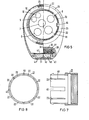
- FIG. 5 shows a head view of the endoscope probe with the addition of ultrasound.
- the reference numerals are the same as in the exemplary embodiment in FIG. 4.
- a carrier body 40 serves as a carrier for the transducer elements 31. consists of epoxy resin with oxidized tungsten powder.
- Carrier body 40 and transducer elements 31 are mounted in the array housing 30 by means of mounting pieces 41.
- the component 42 is a printed circuit board. This can also be omitted if necessary.
- the application surface of the array 13 is provided with an adaptation layer 43 for the converter elements 31.
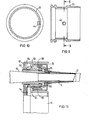
- the tube sleeve 23 is provided with a special locking pin 44.
- the locking pin 44 is, as indicated in FIGS. 9 and 10, soldered into the hose sleeve 23.
- the locking pin 44 engages in a matching wider slot 45 (see FIGS. 7 and 8) between two spring tongues 22 of the snap sleeve 21.
- the remaining slots between the spring tongues 22 of the snap sleeve 21 are less wide than the slot 45.
- some of the narrower slots are designated by 46.
- FIG. 11 shows the proximal connection of the hose cover 12.
- the proximal end of the hose is upside down provided with a sliding sleeve 50, which can be pushed onto the conical end part 51 of the endoscope 1, which merges into the endoscope probe 5.
- the electronic part 15 held thereon is seated on the sliding sleeve 50 by means of a sliding ring 52.
- the sliding ring 52 has the configuration shown in section in FIG. Accordingly, it contains in its interior a circular arrangement of sockets 53 with lines 54. These sockets 53 fit pins 55.
- These pins 55 are, in a corresponding circular arrangement, part of the end connector 14 for coupling the proximal ends of the signal lines 25 to the electronic part 15.
- FIG. 12 shows a further preferred exemplary embodiment of an ultrasound endoscope. This embodiment is a modification of the exemplary embodiment according to FIG. 4.
- FIG. 12 shows a section through the end part of the endoscope. The same and corresponding parts are provided with the same reference numerals as in FIG. 3.
- the embodiment shown in FIG. 12 does not require a snap ring.
- the endoscope probe 5 again contains at its distal end.
- End piece 6a This end 6a is l substantially a cylindrical metal piece of conventional design which has the end surface shown in FIG. 2
- the end piece 6a has an external thread 20, onto which a cylindrical fitting piece 21a in the form of a tube is screwed.
- This screw-on piece 21a extends somewhat beyond the end face 6 with its end.
- the distal end of this fitting piece 21a contains an annular groove 60.
- a retaining ring 61 is snapped into the groove 60.
- the adapter 21a essentially fulfills the function of the snap base 21 shown in FIG. 3.
- a longer tube 23a is applied to the endoscope probe 5 and to the fitting piece 21a.
- the effect of this corresponds to the tube base 23 according to FIG. 3.
- the position of this tube 23a is determined with the aid of the snap ring 61 mentioned above.
- an O-ring 63 is provided in order to prevent liquid from penetrating into the space between the endoscope probe 5 and the tube 23.
- This 0-ring 63 is arranged between the fitting 21a and the end part of the tube 23a.
- the 0-ring 63 is located in an annular groove 63 which is embedded in the outer surface of the fitting 21a.
- the 0-ring 63 thus closes the inside of the tube 23a. This is important because the end part of the gastroscope is exposed to liquids during use or especially during rinsing of the optics.
- the tube 23a carries an elongated housing 29a, which opens into the housing 30 of the ultrasound head 13.
- the entire housing 29a, 30 is preferably made of a plastic. It is noteworthy that a gap 65 is provided between the outer surface of the tube 23a and the inner surface of the housing 29a.
- a piece of hose 12 is housed within this space 65.
- the tube piece 12 itself comprises a shield 26 which contains a larger number of lead wires 28 which lead to the ultrasound transmitter 13.
- the shield 26 is held in place by a wire 24 which is wound both around the tube 23a and around the shield 26.
- the wires 28 are electrical signal connections which connect the ultrasound transmitter 13 to an external control and processing unit (not shown).
- the tube piece 12 slipped over the endoscope probe 6.
- the electrical signal lines 28 are accommodated in the hose wall.
Landscapes
- Life Sciences & Earth Sciences (AREA)
- Health & Medical Sciences (AREA)
- Biomedical Technology (AREA)
- Molecular Biology (AREA)
- Nuclear Medicine, Radiotherapy & Molecular Imaging (AREA)
- Pathology (AREA)
- Radiology & Medical Imaging (AREA)
- Engineering & Computer Science (AREA)
- Physics & Mathematics (AREA)
- Heart & Thoracic Surgery (AREA)
- Medical Informatics (AREA)
- Biophysics (AREA)
- Surgery (AREA)
- Animal Behavior & Ethology (AREA)
- General Health & Medical Sciences (AREA)
- Public Health (AREA)
- Veterinary Medicine (AREA)
- Ultra Sonic Daignosis Equipment (AREA)
- Endoscopes (AREA)
Applications Claiming Priority (2)
| Application Number | Priority Date | Filing Date | Title |
|---|---|---|---|
| DE19823214793 DE3214793A1 (de) | 1982-04-21 | 1982-04-21 | Ultraschall-endoskop |
| DE3214793 | 1982-04-21 |
Publications (1)
| Publication Number | Publication Date |
|---|---|
| EP0092080A1 true EP0092080A1 (fr) | 1983-10-26 |
Family
ID=6161524
Family Applications (1)
| Application Number | Title | Priority Date | Filing Date |
|---|---|---|---|
| EP83103181A Ceased EP0092080A1 (fr) | 1982-04-21 | 1983-03-30 | Endoscope ultrasonique |
Country Status (3)
| Country | Link |
|---|---|
| EP (1) | EP0092080A1 (fr) |
| JP (1) | JPS58188425A (fr) |
| DE (1) | DE3214793A1 (fr) |
Cited By (6)
| Publication number | Priority date | Publication date | Assignee | Title |
|---|---|---|---|---|
| EP0123594A1 (fr) * | 1983-04-06 | 1984-10-31 | Universite Francois Rabelais | Sonde endoscopique de visualisation et d'échographie ultrasonore à balayage |
| FR2569341A1 (fr) * | 1984-08-27 | 1986-02-28 | Inst Nat Sante Rech Med | Sonde ultrasonore d'examen intracorporel |
| FR2585944A1 (fr) * | 1985-08-12 | 1987-02-13 | Alvar Electronic Sa | Sonde a ultrasons implantable et son pro cede de fabrication |
| EP0367472A3 (fr) * | 1988-11-02 | 1991-01-16 | Cardiometrics, Inc. | Ensemble de fil de guidage |
| CN103860130A (zh) * | 2012-12-13 | 2014-06-18 | 蒋小华 | 一种新型超声波探头胃镜探管 |
| CN110809432A (zh) * | 2017-06-29 | 2020-02-18 | 泰尔茂株式会社 | 图像诊断用导管 |
Families Citing this family (2)
| Publication number | Priority date | Publication date | Assignee | Title |
|---|---|---|---|---|
| JP2682243B2 (ja) * | 1991-01-30 | 1997-11-26 | 富士写真光機株式会社 | ラジアル走査式超音波検査装置 |
| JP2682244B2 (ja) * | 1991-01-30 | 1997-11-26 | 富士写真光機株式会社 | ラジアル走査式超音波検査装置 |
Citations (11)
| Publication number | Priority date | Publication date | Assignee | Title |
|---|---|---|---|---|
| DE606098C (de) * | 1933-07-21 | 1934-11-24 | Erich Kalpen Dr | Einrichtung zur Untersuchung des Magens |
| DE1211360B (de) * | 1958-02-22 | 1966-02-24 | Dr Abdul Hayee Saeed | Vorrichtung zur Einfuehrung eines Bronchialkatheters |
| US3315663A (en) * | 1964-04-02 | 1967-04-25 | Goldfarb Herman | Bronchoscope having means for producing mechanical vibrations in the bronchial tract |
| US3556079A (en) * | 1967-05-16 | 1971-01-19 | Haruo Omizo | Method of puncturing a medical instrument under guidance of ultrasound |
| DE2305501A1 (de) * | 1973-02-05 | 1974-08-15 | Siemens Ag | In den koerper eines patienten einfuehrbare ultraschall-sonde |
| FR2242060A1 (fr) * | 1973-09-03 | 1975-03-28 | Akad Tekn Videnskaber | |
| DE2626179A1 (de) * | 1976-06-11 | 1977-12-22 | Karl Storz | Rektoskop, insbesondere zur luftaufblaehung und verfahren zur anwendung desselben |
| DE2736102A1 (de) * | 1976-08-12 | 1978-02-16 | Yeda Res & Dev | Wandleranordnung zum abtasten von lebendem gewebe |
| EP0027185A1 (fr) * | 1979-09-17 | 1981-04-22 | Olympus Optical Co., Ltd. | Enveloppe de protection pour la section flexible d'un endoscope |
| US4319580A (en) * | 1979-08-28 | 1982-03-16 | The Board Of Regents Of The University Of Washington | Method for detecting air emboli in the blood in an intracorporeal blood vessel |
| EP0077923A1 (fr) * | 1981-10-15 | 1983-05-04 | Siemens Aktiengesellschaft | Transducteur à ultrasons à introduire dans un corps |
-
1982
- 1982-04-21 DE DE19823214793 patent/DE3214793A1/de not_active Withdrawn
-
1983
- 1983-03-30 EP EP83103181A patent/EP0092080A1/fr not_active Ceased
- 1983-04-12 JP JP58064391A patent/JPS58188425A/ja active Pending
Patent Citations (11)
| Publication number | Priority date | Publication date | Assignee | Title |
|---|---|---|---|---|
| DE606098C (de) * | 1933-07-21 | 1934-11-24 | Erich Kalpen Dr | Einrichtung zur Untersuchung des Magens |
| DE1211360B (de) * | 1958-02-22 | 1966-02-24 | Dr Abdul Hayee Saeed | Vorrichtung zur Einfuehrung eines Bronchialkatheters |
| US3315663A (en) * | 1964-04-02 | 1967-04-25 | Goldfarb Herman | Bronchoscope having means for producing mechanical vibrations in the bronchial tract |
| US3556079A (en) * | 1967-05-16 | 1971-01-19 | Haruo Omizo | Method of puncturing a medical instrument under guidance of ultrasound |
| DE2305501A1 (de) * | 1973-02-05 | 1974-08-15 | Siemens Ag | In den koerper eines patienten einfuehrbare ultraschall-sonde |
| FR2242060A1 (fr) * | 1973-09-03 | 1975-03-28 | Akad Tekn Videnskaber | |
| DE2626179A1 (de) * | 1976-06-11 | 1977-12-22 | Karl Storz | Rektoskop, insbesondere zur luftaufblaehung und verfahren zur anwendung desselben |
| DE2736102A1 (de) * | 1976-08-12 | 1978-02-16 | Yeda Res & Dev | Wandleranordnung zum abtasten von lebendem gewebe |
| US4319580A (en) * | 1979-08-28 | 1982-03-16 | The Board Of Regents Of The University Of Washington | Method for detecting air emboli in the blood in an intracorporeal blood vessel |
| EP0027185A1 (fr) * | 1979-09-17 | 1981-04-22 | Olympus Optical Co., Ltd. | Enveloppe de protection pour la section flexible d'un endoscope |
| EP0077923A1 (fr) * | 1981-10-15 | 1983-05-04 | Siemens Aktiengesellschaft | Transducteur à ultrasons à introduire dans un corps |
Non-Patent Citations (1)
| Title |
|---|
| IEEE TRANSACTIONS ON SONICS AND ULTRASONICS, Band SU-27, Nr. 6, November 1980, Seiten 277-286, IEEE, New York, USA * |
Cited By (9)
| Publication number | Priority date | Publication date | Assignee | Title |
|---|---|---|---|---|
| EP0123594A1 (fr) * | 1983-04-06 | 1984-10-31 | Universite Francois Rabelais | Sonde endoscopique de visualisation et d'échographie ultrasonore à balayage |
| FR2569341A1 (fr) * | 1984-08-27 | 1986-02-28 | Inst Nat Sante Rech Med | Sonde ultrasonore d'examen intracorporel |
| FR2585944A1 (fr) * | 1985-08-12 | 1987-02-13 | Alvar Electronic Sa | Sonde a ultrasons implantable et son pro cede de fabrication |
| EP0217689A1 (fr) * | 1985-08-12 | 1987-04-08 | Virbac S.A. | Sonde à ultrasons implantable |
| US4823800A (en) * | 1985-08-12 | 1989-04-25 | Virbac, A French Corporation | Implantable ultrasonic probe and method of manufacturing the same |
| EP0367472A3 (fr) * | 1988-11-02 | 1991-01-16 | Cardiometrics, Inc. | Ensemble de fil de guidage |
| CN103860130A (zh) * | 2012-12-13 | 2014-06-18 | 蒋小华 | 一种新型超声波探头胃镜探管 |
| CN110809432A (zh) * | 2017-06-29 | 2020-02-18 | 泰尔茂株式会社 | 图像诊断用导管 |
| US11596310B2 (en) * | 2017-06-29 | 2023-03-07 | Terumo Kabushiki Kaisha | Image diagnosis catheter |
Also Published As
| Publication number | Publication date |
|---|---|
| JPS58188425A (ja) | 1983-11-02 |
| DE3214793A1 (de) | 1983-10-27 |
Similar Documents
| Publication | Publication Date | Title |
|---|---|---|
| DE2938882C2 (de) | Lösbare Kupplung für einen schlauchförmigen Versorgungsanschluß eines Endoskops | |
| DE19609888B4 (de) | Endoskopsatz | |
| DE3108038C2 (fr) | ||
| DE3817915C2 (de) | Flexibles Endoskop | |
| DE69832408T2 (de) | Führungskatheter zur intravaskulären bilderzeugung | |
| DE69333482T2 (de) | Katheter zur Bilderzeugung mittels Ultraschall | |
| DE2948564C2 (de) | Anschlußteil für ein Endoskop | |
| DE10122710B4 (de) | Vorwärts blickendes, radial abtastendes Ultraschallendoskop | |
| DE69930801T2 (de) | Bidirektionaler Bedienungshandgriff für einen Lenkkatheter | |
| DE3885124T2 (de) | Vorrichtung zur Untersuchung der Beleuchtung oder Bestrahlung einer Körperhöhle. | |
| DE19935842C2 (de) | Intracavitäre Ultraschallsonde mit Sektorabtastung | |
| DE68926773T2 (de) | Führungsdraht-Zusammenbau | |
| DE602005000297T2 (de) | Ultraschall-Endoskop | |
| DE29502880U1 (de) | Endoskop für Ultraschallechographie | |
| DE3834230A1 (de) | Resektoskop | |
| WO2012025179A1 (fr) | Elément de connexion électrique et système d'endoscopie | |
| DE10254609B4 (de) | Endoskopkopf | |
| EP0077923A1 (fr) | Transducteur à ultrasons à introduire dans un corps | |
| DE502268T1 (de) | Elektrochirurgisches instrument mit einer nadelelektrode zum schneiden und einer punktelektrode zum koagulieren. | |
| DE10334525A1 (de) | Bipolares Hochfrequenz-Behandlungsinstrument für ein Endoskop | |
| DE69112532T2 (de) | Transösophagischer Probenschaft. | |
| DE102015015993B4 (de) | Endoskop | |
| EP0650382B1 (fr) | Microconnecteur et dispositif et procede pour la realisation d'un element microconnecteur | |
| DE10122709B4 (de) | Radial abtastendes, vorwärts blickendes Ultraschallendoskop | |
| DE3738633A1 (de) | Steckvorrichtung fuer endoskope |
Legal Events
| Date | Code | Title | Description |
|---|---|---|---|
| PUAI | Public reference made under article 153(3) epc to a published international application that has entered the european phase |
Free format text: ORIGINAL CODE: 0009012 |
|
| AK | Designated contracting states |
Designated state(s): AT CH DE FR GB LI |
|
| 17P | Request for examination filed |
Effective date: 19831213 |
|
| STAA | Information on the status of an ep patent application or granted ep patent |
Free format text: STATUS: THE APPLICATION HAS BEEN REFUSED |
|
| 18R | Application refused |
Effective date: 19860728 |
|
| RIN1 | Information on inventor provided before grant (corrected) |
Inventor name: HETZ, WALTER |