EP0092081B1 - Culasse de cylindre en métal léger avec insertion de siège de soupape - Google Patents
Culasse de cylindre en métal léger avec insertion de siège de soupape Download PDFInfo
- Publication number
- EP0092081B1 EP0092081B1 EP83103191A EP83103191A EP0092081B1 EP 0092081 B1 EP0092081 B1 EP 0092081B1 EP 83103191 A EP83103191 A EP 83103191A EP 83103191 A EP83103191 A EP 83103191A EP 0092081 B1 EP0092081 B1 EP 0092081B1
- Authority
- EP
- European Patent Office
- Prior art keywords
- valve seat
- seat insert
- block
- cylinder head
- light metal
- Prior art date
- Legal status (The legal status is an assumption and is not a legal conclusion. Google has not performed a legal analysis and makes no representation as to the accuracy of the status listed.)
- Expired
Links
- 239000002184 metal Substances 0.000 title claims description 30
- 229910052751 metal Inorganic materials 0.000 title claims description 29
- 238000003825 pressing Methods 0.000 claims description 7
- 238000005266 casting Methods 0.000 claims description 4
- 229910000838 Al alloy Inorganic materials 0.000 description 6
- XLYOFNOQVPJJNP-UHFFFAOYSA-N water Substances O XLYOFNOQVPJJNP-UHFFFAOYSA-N 0.000 description 6
- 238000003754 machining Methods 0.000 description 4
- 238000004519 manufacturing process Methods 0.000 description 4
- 238000009434 installation Methods 0.000 description 3
- 239000000567 combustion gas Substances 0.000 description 2
- 238000003780 insertion Methods 0.000 description 2
- 230000037431 insertion Effects 0.000 description 2
- 239000000463 material Substances 0.000 description 2
- 238000000034 method Methods 0.000 description 2
- 229910000831 Steel Inorganic materials 0.000 description 1
- 230000008859 change Effects 0.000 description 1
- 238000002485 combustion reaction Methods 0.000 description 1
- 239000000498 cooling water Substances 0.000 description 1
- 229910001234 light alloy Inorganic materials 0.000 description 1
- 229910001092 metal group alloy Inorganic materials 0.000 description 1
- 238000013021 overheating Methods 0.000 description 1
- 230000008569 process Effects 0.000 description 1
- 230000009467 reduction Effects 0.000 description 1
- 239000007787 solid Substances 0.000 description 1
- 239000010959 steel Substances 0.000 description 1
- 230000009466 transformation Effects 0.000 description 1
Images
Classifications
-
- F—MECHANICAL ENGINEERING; LIGHTING; HEATING; WEAPONS; BLASTING
- F01—MACHINES OR ENGINES IN GENERAL; ENGINE PLANTS IN GENERAL; STEAM ENGINES
- F01L—CYCLICALLY OPERATING VALVES FOR MACHINES OR ENGINES
- F01L3/00—Lift-valve, i.e. cut-off apparatus with closure members having at least a component of their opening and closing motion perpendicular to the closing faces; Parts or accessories thereof
- F01L3/22—Valve-seats not provided for in preceding subgroups of this group; Fixing of valve-seats
-
- F—MECHANICAL ENGINEERING; LIGHTING; HEATING; WEAPONS; BLASTING
- F02—COMBUSTION ENGINES; HOT-GAS OR COMBUSTION-PRODUCT ENGINE PLANTS
- F02F—CYLINDERS, PISTONS OR CASINGS, FOR COMBUSTION ENGINES; ARRANGEMENTS OF SEALINGS IN COMBUSTION ENGINES
- F02F1/00—Cylinders; Cylinder heads
- F02F1/24—Cylinder heads
- F02F1/26—Cylinder heads having cooling means
- F02F1/36—Cylinder heads having cooling means for liquid cooling
- F02F1/38—Cylinder heads having cooling means for liquid cooling the cylinder heads being of overhead valve type
-
- Y—GENERAL TAGGING OF NEW TECHNOLOGICAL DEVELOPMENTS; GENERAL TAGGING OF CROSS-SECTIONAL TECHNOLOGIES SPANNING OVER SEVERAL SECTIONS OF THE IPC; TECHNICAL SUBJECTS COVERED BY FORMER USPC CROSS-REFERENCE ART COLLECTIONS [XRACs] AND DIGESTS
- Y10—TECHNICAL SUBJECTS COVERED BY FORMER USPC
- Y10T—TECHNICAL SUBJECTS COVERED BY FORMER US CLASSIFICATION
- Y10T29/00—Metal working
- Y10T29/49—Method of mechanical manufacture
- Y10T29/49229—Prime mover or fluid pump making
- Y10T29/4927—Cylinder, cylinder head or engine valve sleeve making
- Y10T29/49272—Cylinder, cylinder head or engine valve sleeve making with liner, coating, or sleeve
-
- Y—GENERAL TAGGING OF NEW TECHNOLOGICAL DEVELOPMENTS; GENERAL TAGGING OF CROSS-SECTIONAL TECHNOLOGIES SPANNING OVER SEVERAL SECTIONS OF THE IPC; TECHNICAL SUBJECTS COVERED BY FORMER USPC CROSS-REFERENCE ART COLLECTIONS [XRACs] AND DIGESTS
- Y10—TECHNICAL SUBJECTS COVERED BY FORMER USPC
- Y10T—TECHNICAL SUBJECTS COVERED BY FORMER US CLASSIFICATION
- Y10T29/00—Metal working
- Y10T29/49—Method of mechanical manufacture
- Y10T29/49229—Prime mover or fluid pump making
- Y10T29/49298—Poppet or I.C. engine valve or valve seat making
- Y10T29/49306—Valve seat making
Definitions
- the present invention relates in general to light metal cylinder heads for internal combustion engines and more particularly to valve seat inserts thereof.
- Such light metal cylinder head comprises a block cast in light metal and having intake and exhaust ports and an annular valve seat insert embedded in said block around said valve seat insert.
- Valve seat inserts are widely used in current automobile engines having light metal or aluminum alloy cylinder heads.
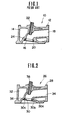
- Fig. 1 shows a prior art aluminum alloy cylinder head 10 having a cast, aluminum alloy block 12 with a water jacket 14.
- the block 12 has a hole 16 prepared by machining at an end of an intake or exhaust port 18.
- a valve seat insert 20 made of hard, heat-resisting metal is inserted into the hole 16 and held in place by interference fit. After insertion, the valve seating surface of the valve seat insert 20 is ground in a manner as to be aligned with a valve guide 22.
- the prior art light metal cylinder head of the above described type encounters the following drawbacks. That is, it is of great importance for the valve seat insert 20 to fit tightly all around the hole 16 in order to provide efficient heat transfer from the valve seat insert 20 to the block 12. This however, necessitates highly accurate machining of the valve seat insert 20 and the hole 16 and therefore results in an expensive manufacturing cost. Further, the pressed-in insert 20 requires a wall portion 24 of the block 12 surrounding the hole 16 to be thick enough to have sufficient strength. This results in poor heat transfer from the valve seat insert 20 to the water jacket 14.
- valve seat insert in the cylinder head by casting the receiving block portion of the cylinder head around the valve seat insert (DE-C-929 157).
- valve seat insert consists of heat-resisting sintered metal providing sufficient wear resistance.
- valve seat insert In order not to subject a greater surface of the valve seat insert to the hot combustion gases, the valve seat insert forms a tapered or cylindrical ring having a small end periphery surface which is exposed to form a valve seating surface, whereas the remaining surface of the valve seat insert is nearly completely embedded in the light alloy cylinder head.
- a light metal cylinder head in accordance with the precharacterising portion of claim 1 which performs excellent heat transfer between a valve seat insert and an associated cylinder head block, particularly to an associated water jacket disposed therein, enabling the reduction of the mass of the respective valve seat support portion of the cylinder head and to further reduce manufacturing costs of the final cylinder head block.
- Another object of the invention is to provide a valve seat with an increased heat transferring surface having means improving connection rigidity between the cylinder head block and the valve seat insert.
- the valve seating surface should correspond to the shape of the inner wall surface of the port to which the valve seat insert is assembled without essentially amending the port opening, respectively.
- an improved light metal cylinder head which comprises a block that is cast in light metal and a valve seat insert that is embedded in the block by casting the block around the valve seat insert.
- the valve seat insert is formed from a heat-resisting sheet metal into a tapered ring by pressing.
- the tapered ring comprises a pair of outward flanges at the axially opposed ends thereof embedded in the cylinder head block so as to provide a firm joint between the valve seat insert and said block.
- the valve seat insert further exhibits a tapered inner circumferential surface smoothly and consecutively joined to one of the block ports and forms a valve seating surface at the larger diameter end of the ring. Except for said inner circumferential surface including the valve seating surface all of the exterior surfaces of the tapered ring are in close contact with the cylinder head block receiving the valve seat insert.
- the present invention sets forth a valve seat insert with a relatively small valve seating surface and without any remarkable change of respective port diameter being joing smoothly and consecutively to the inner wall of the port.
- the outer flange forming part of the enlarged diameter portion of the valve seat insert contributes to establish a valve seating surface.
- the respective tongue-like flange projections serve as heat conducting members providing an excellent heattransferfrom the valve seat insert to a cooling water jacket of the cylinder head due to the firm joint as well as to the considerably enlarged heat transferring contact surface between both members.
- the invention provides a valve seat insert for a light metal cylinder head being assembled with an extremely high connection rigidity enabling low wall thickness within the cylinder head between the valve seat insert and an adjacent water jacket, thus remarkably improving heat removal from the valve seat insert. Additionally, the flanges are also adapted to increase the structural strength of the valve seat insert and, thus, make it possible to form the valve seat insert from a thinner sheet metal.
- a light metal cylinder head according to the present invention is generally indicated at 26 and comprises a cast block 28 and a valve seat insert 30 embedded in the block 28 at a predetermined position thereon by casting the block 28 around the valve seat insert 30.
- the block 28 is cast in light metal such as aluminum alloy and is formed with a water jacket 32 and also formed with intake and exhaust ports though only one port that may be either an intake port or an exhaust port is shown and designated by 34.
- the valve seat insert 30 is made of hard, heat-resisting metal such as SUH 33 (a heat-resisting steel according to Japanese Industrial Standards) and embedded in a wall portion 36 of the block 28 at an end of the intake or exhaust port 34.
- the valve seat insert 30 is in the form of a tapered ring or tube having a tapered inner surface smoothly and consecutively joined to the inner wall of the intake or exhaust port 34.
- the valve seat insert 30 has at the axially opposed ends thereof a pair of outward flanges 30a and 30b that are embedded in the block 28 to provide a firm joint between the valve seat insert 30 and the block 28.
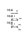
- the valve seat insert 30 is formed from a sheet metal by pressing or metal stamping as shown in Figs. 3A-3C. That is, in producing the valve seat insert 30, an annular sheet metal blank 30' is first prepared. The blank 30' is formed into a tapered tube having the flange 30b at the larger diameter end thereof as shown in Fig. 3B and then formed with the flange 30a at the smaller diameter end as shown in Fig. 3C.
- the valve seat insert 30 is first prepared preferably by pressing as mentioned above and hardened to have a good resistance to wear. The valve seat insert 30 is then set in a mould and afterwards a mass of molten aluminum alloy is poured into the mould and allowed to be cooled. In this connection, the pouring temperature should be lower than the transformation temperature of the heat resisting metal from which the valve seat insert 30 is formed. Selection of the materials for the block 28 and the valve seat insert 30 is made to meet this requirement. When the mass of aluminum alloy becomes solid, the valve seat insert 30 is firmly and integrally secured to the block 28. After being embedded in the block 28, the inner circumferential surface of the valve seat insert 30 is finish ground to form at the larger diameter end thereof a valve seating surface 30c that is aligned with a valve guide 38.
- valve seat insert 30 is united to the block 28 by a thermal and mechanical joint, that is, integrally joined with the block 28, thus providing excellent heat transfer from the valve seat insert 30 to the block 28.
- valve seat insert 30 does not require the highly accurate machining as in the case of the prior art insert, thus making it possible to reduce the manufacturing cost of the cylinder head 26.
- valve seat insert 30 per se can be produced economically by pressing, making it possible to further reduce the manufacturing cost.
- valve seat insert 30 can be a sheet metal pressing since it does not subjected to any large stress in installation, whereas the pressed-in valve seat insert in the prior art cylinder head is subjected to considerable stresses in installation and therefore cannot be so thin.
- the cylinder head block wall portion 36 to which the valve seat insert 30 is embedded can be thinner as compared with the corresponding wall portion of the comparable prior art cylinder head block since it is unnecessary for the wall portion 36 to have sufficient strength for withstanding the stresses incurred in the insertion of the pressed-in valve seat insert, thus providing excellent heat transfer from the valve seat insert 30 to the water jacket-32.
Landscapes
- Engineering & Computer Science (AREA)
- Mechanical Engineering (AREA)
- General Engineering & Computer Science (AREA)
- Chemical & Material Sciences (AREA)
- Combustion & Propulsion (AREA)
- Cylinder Crankcases Of Internal Combustion Engines (AREA)
Claims (1)
- Culasse de cylindre en métal léger (26) comprenant:un bloc (28) coulé en métal léger et ayant des orifices d'admission et d'échappement (34) etune insertion annulaire de siège de soupape (30) noyée dans ledit block (28) en coulant ledit block (28) autour de ladite insertion (30) de siège de soupape; caractérisée en ce queladite insertion de siège de soupape (30) est formée d'un métal en tôle résistant à la chaleur en une bague effilée par emboutissage et a, à ses extrémités axialement opposées, deux ailes (30a, 30b), vers l'extérieur, qui sont noyées dans ledit bloc (28), pour produire un joint ferme entre ladite insertion de siège de soupape (30) et ledit bloc (28) et a également une surface circonférentielle interne effilée jointe régulièrement et consécutivement à l'un desdits orifices et contenant, à son extrémité de plus grand diamètre, une surface de siège de soupape (30b), ladite insertion de siège de soupape (30) étant en contact par toutes ses surfaces extérieures, à l'exception de ladite surface circonférentielle interne, avec ledit bloc (28).
Applications Claiming Priority (2)
| Application Number | Priority Date | Filing Date | Title |
|---|---|---|---|
| JP57066514A JPS58183804A (ja) | 1982-04-21 | 1982-04-21 | 内燃機関の軽合金製シリンダヘツド |
| JP66514/82 | 1982-04-21 |
Publications (2)
| Publication Number | Publication Date |
|---|---|
| EP0092081A1 EP0092081A1 (fr) | 1983-10-26 |
| EP0092081B1 true EP0092081B1 (fr) | 1986-11-05 |
Family
ID=13318030
Family Applications (1)
| Application Number | Title | Priority Date | Filing Date |
|---|---|---|---|
| EP83103191A Expired EP0092081B1 (fr) | 1982-04-21 | 1983-03-30 | Culasse de cylindre en métal léger avec insertion de siège de soupape |
Country Status (4)
| Country | Link |
|---|---|
| US (1) | US4570585A (fr) |
| EP (1) | EP0092081B1 (fr) |
| JP (1) | JPS58183804A (fr) |
| DE (1) | DE3367429D1 (fr) |
Cited By (2)
| Publication number | Priority date | Publication date | Assignee | Title |
|---|---|---|---|---|
| DE4141100A1 (de) * | 1991-12-13 | 1993-06-17 | Audi Ag | Verfahren zum einsetzen eines ventilsitzringes |
| DE102008015854A1 (de) | 2008-03-27 | 2009-10-01 | Volkswagen Ag | Ventilsitzring |
Families Citing this family (25)
| Publication number | Priority date | Publication date | Assignee | Title |
|---|---|---|---|---|
| US4773382A (en) * | 1985-07-29 | 1988-09-27 | Tfs, Inc. | Head for high performance internal combustion engine |
| US4686948A (en) * | 1985-07-29 | 1987-08-18 | Tfs, Inc. | Head for high performance internal combustion engine |
| US4919092A (en) * | 1985-07-29 | 1990-04-24 | Tfs, Inc. | In-line cylinder head for internal combustion engine |
| US5076224A (en) * | 1985-07-29 | 1991-12-31 | Tfs, Inc. | In-line cylinder head for internal combustion engine |
| US5257612A (en) * | 1985-07-29 | 1993-11-02 | Autosales, Incorporated | In-line cylinder head for an internal combustion engine |
| US4688527A (en) * | 1986-03-31 | 1987-08-25 | Chrysler Motors Corporation | Ceramic valve guide and seat |
| JPS62298682A (ja) * | 1986-06-18 | 1987-12-25 | Diesel Kiki Co Ltd | 圧縮機における吐出弁構造 |
| US4934351A (en) * | 1988-12-07 | 1990-06-19 | Ford Motor Company | Fabricating internal combustion engine cylinder heads with close tolerance internal surfaces |
| US4896638A (en) * | 1988-12-07 | 1990-01-30 | Ford Motor Company | Fabricating internal combustion engine cylinder heads with close tolerance internal surfaces |
| JPH0296402U (fr) * | 1989-01-19 | 1990-08-01 | ||
| US5197189A (en) * | 1990-09-06 | 1993-03-30 | Volkswagen Ag | Method of making a cylinder head with a port liner |
| DE4321832C1 (de) * | 1993-06-28 | 1994-12-01 | Mannesmann Ag | 2/2-Wegesitzventil |
| US5802716A (en) * | 1994-09-30 | 1998-09-08 | Toyota Jidosha Kabushiki Kaisha | Method for bonding a valve seat with a cylinder head |
| JPH08296416A (ja) * | 1995-04-26 | 1996-11-12 | Yamaha Motor Co Ltd | バルブシートの接合方法 |
| US5745993A (en) * | 1996-02-27 | 1998-05-05 | Yamaha Hatsudoki Kabushiki Kaisha | Valve seat |
| JP3546261B2 (ja) * | 1996-03-05 | 2004-07-21 | ヤマハ発動機株式会社 | 異種金属材料の接合方法 |
| US5775591A (en) * | 1996-08-16 | 1998-07-07 | Fauci; Dino A. | Portable pressure cleaning device |
| US6017591A (en) * | 1996-11-14 | 2000-01-25 | Ford Global Technologies, Inc. | Method of making adherently sprayed valve seats |
| DE19942386B4 (de) * | 1999-09-04 | 2013-10-02 | Pro-Beam Systems Gmbh | Verfahren zur Randschichtbehandlung von Oberflächen mittels Energiestrahl |
| US20040238780A1 (en) * | 2003-06-02 | 2004-12-02 | Gethmann Doug P. | Control valve with integrated hardened valve seat |
| US20160076480A1 (en) * | 2012-02-04 | 2016-03-17 | David Endrigo | Valve seats for cylinder heads in aircraft engines |
| JP6015682B2 (ja) * | 2014-01-24 | 2016-10-26 | 株式会社デンソー | スプール弁におけるバルブボディの製造方法 |
| US20160333751A1 (en) * | 2015-05-07 | 2016-11-17 | Frank J. Ardezzone | Engine Insert and Process for Installing |
| US10774939B2 (en) | 2018-04-12 | 2020-09-15 | Cla-Val Co. | Valve with integral insert-cast seat and related method |
| CN110425050A (zh) * | 2019-07-26 | 2019-11-08 | 中国第一汽车股份有限公司 | 一种气缸盖总成成型工艺及气缸盖 |
Family Cites Families (11)
| Publication number | Priority date | Publication date | Assignee | Title |
|---|---|---|---|---|
| FR729242A (fr) * | 1931-12-23 | 1932-07-20 | Siemens Ag | élément d'un dispositif technique, par exemple siège de soupape ou guide de soupape d'un moteur à combustion interne, élément ne subissant pas de fortes sollicitations thermiques sur tous les côtés |
| DE575295C (de) * | 1931-12-24 | 1933-04-26 | Siemens & Halske Akt Ges | Aus Berylliumlegierung bestehende Ventilsitze, Ventilfuehrung u. dgl., insbesondere fuer Brennkraftmaschinen |
| US2101970A (en) * | 1933-07-26 | 1937-12-14 | Union Carbide & Carbon Corp | Valve seat |
| US2036520A (en) * | 1934-06-18 | 1936-04-07 | Patrick J Fitzgerald | Folded and pressed ring |
| FR807344A (fr) * | 1935-06-25 | 1937-01-09 | Perfectionnements apportés aux moteurs à explosion ou combustion interne, notamment à ceux à soupape en tête | |
| US2178895A (en) * | 1939-03-09 | 1939-11-07 | Leo Myers | Valve seat inset |
| GB625394A (en) * | 1942-07-03 | 1949-06-27 | Mallory Metallurg Prod Ltd | Improvements in and relating to valve seats for internal combustion engines |
| US2600529A (en) * | 1946-06-19 | 1952-06-17 | Fairchild Engine & Airplane | Engine cylinder construction for cooling valve seat inserts |
| DE929157C (de) * | 1951-10-18 | 1955-06-20 | Volkswagenwerk G M B H | Ventilsitzring an Zylinderkoepfen fuer Brennkraftmaschinen |
| FR1238335A (fr) * | 1959-06-29 | 1960-08-12 | Hispano Suiza Sa | Perfectionnements apportés aux pièces en métal léger, notamment aux culasses de moteur, devant comporter des inclusions métalliques, et aux procédés pour leur élaboration |
| US3428035A (en) * | 1966-12-01 | 1969-02-18 | Ford Motor Co | Internal combustion engine valve seat |
-
1982
- 1982-04-21 JP JP57066514A patent/JPS58183804A/ja active Pending
-
1983
- 1983-03-30 DE DE8383103191T patent/DE3367429D1/de not_active Expired
- 1983-03-30 EP EP83103191A patent/EP0092081B1/fr not_active Expired
- 1983-04-05 US US06/482,306 patent/US4570585A/en not_active Expired - Fee Related
Cited By (2)
| Publication number | Priority date | Publication date | Assignee | Title |
|---|---|---|---|---|
| DE4141100A1 (de) * | 1991-12-13 | 1993-06-17 | Audi Ag | Verfahren zum einsetzen eines ventilsitzringes |
| DE102008015854A1 (de) | 2008-03-27 | 2009-10-01 | Volkswagen Ag | Ventilsitzring |
Also Published As
| Publication number | Publication date |
|---|---|
| JPS58183804A (ja) | 1983-10-27 |
| DE3367429D1 (en) | 1986-12-11 |
| US4570585A (en) | 1986-02-18 |
| EP0092081A1 (fr) | 1983-10-26 |
Similar Documents
| Publication | Publication Date | Title |
|---|---|---|
| EP0092081B1 (fr) | Culasse de cylindre en métal léger avec insertion de siège de soupape | |
| US4562799A (en) | Monolithic ceramic cylinder liner and method of making same | |
| EP0744541B1 (fr) | Procédé pour la production de blocs-moteurs | |
| EP0091097B1 (fr) | Soupape d'un moteur à combustion et méthode de production | |
| WO2004022960A1 (fr) | Cylindre pour moteur a combustion interne | |
| JP2009520902A (ja) | 内燃機関用のピストン及び該ピストンのための製造方法 | |
| EP0410612B1 (fr) | Chambre de précombustion avec isolation thermique | |
| CN100425880C (zh) | 凸轮轴 | |
| US4487175A (en) | Cylinder head for internal combustion engine | |
| EP0155159A2 (fr) | Piston pour moteur à combustion interne et son procédé de fabrication | |
| US4653161A (en) | Manufacture process for aluminum alloy die-cast cylinders | |
| JP2008522086A (ja) | 内燃機関用のピストン | |
| US20040182332A1 (en) | Liquid-cooled valve seat ring | |
| JPS59131747A (ja) | 嵌込弁座を備えた水冷式の内燃機関並びにその製法 | |
| US3937266A (en) | Method for application of wear-resistant coating | |
| JPH05240347A (ja) | エンジン用ピストン耐摩環 | |
| EP0730085B1 (fr) | Culasse et méthode pour fabriquer un siège de soupapes | |
| US3130461A (en) | Cooling passages in cast aluminum cylinder heads and blocks | |
| US1683077A (en) | Valve for internal-combustion engines | |
| US4574865A (en) | Method of making a finned cast recuperator tube | |
| JPH0138277Y2 (fr) | ||
| EP0191008A1 (fr) | Carapace ou objet tubulaire et leur procédé de fabrication | |
| JPS6338345Y2 (fr) | ||
| JPH068243Y2 (ja) | 内燃機関用動弁機構の鋳鋼製中空カムシャフト | |
| JPS6048624B2 (ja) | アルミニウム合金製シリンダの製造法 |
Legal Events
| Date | Code | Title | Description |
|---|---|---|---|
| PUAI | Public reference made under article 153(3) epc to a published international application that has entered the european phase |
Free format text: ORIGINAL CODE: 0009012 |
|
| 17P | Request for examination filed |
Effective date: 19830330 |
|
| AK | Designated contracting states |
Designated state(s): DE FR GB |
|
| RAP1 | Party data changed (applicant data changed or rights of an application transferred) |
Owner name: NISSAN MOTOR CO., LTD. |
|
| GRAA | (expected) grant |
Free format text: ORIGINAL CODE: 0009210 |
|
| AK | Designated contracting states |
Kind code of ref document: B1 Designated state(s): DE FR GB |
|
| REF | Corresponds to: |
Ref document number: 3367429 Country of ref document: DE Date of ref document: 19861211 |
|
| ET | Fr: translation filed | ||
| PLBE | No opposition filed within time limit |
Free format text: ORIGINAL CODE: 0009261 |
|
| STAA | Information on the status of an ep patent application or granted ep patent |
Free format text: STATUS: NO OPPOSITION FILED WITHIN TIME LIMIT |
|
| 26N | No opposition filed | ||
| PGFP | Annual fee paid to national office [announced via postgrant information from national office to epo] |
Ref country code: GB Payment date: 19910225 Year of fee payment: 9 |
|
| PGFP | Annual fee paid to national office [announced via postgrant information from national office to epo] |
Ref country code: FR Payment date: 19910307 Year of fee payment: 9 |
|
| PGFP | Annual fee paid to national office [announced via postgrant information from national office to epo] |
Ref country code: DE Payment date: 19910430 Year of fee payment: 9 |
|
| PG25 | Lapsed in a contracting state [announced via postgrant information from national office to epo] |
Ref country code: GB Effective date: 19920330 |
|
| GBPC | Gb: european patent ceased through non-payment of renewal fee | ||
| PG25 | Lapsed in a contracting state [announced via postgrant information from national office to epo] |
Ref country code: FR Effective date: 19921130 |
|
| PG25 | Lapsed in a contracting state [announced via postgrant information from national office to epo] |
Ref country code: DE Effective date: 19921201 |
|
| REG | Reference to a national code |
Ref country code: FR Ref legal event code: ST |