EP0092089B1 - Abtauvorrichtung für einen Kühlschrank - Google Patents
Abtauvorrichtung für einen Kühlschrank Download PDFInfo
- Publication number
- EP0092089B1 EP0092089B1 EP83103255A EP83103255A EP0092089B1 EP 0092089 B1 EP0092089 B1 EP 0092089B1 EP 83103255 A EP83103255 A EP 83103255A EP 83103255 A EP83103255 A EP 83103255A EP 0092089 B1 EP0092089 B1 EP 0092089B1
- Authority
- EP
- European Patent Office
- Prior art keywords
- temperature
- defrosting
- refrigerator according
- evaporator
- compressor
- Prior art date
- Legal status (The legal status is an assumption and is not a legal conclusion. Google has not performed a legal analysis and makes no representation as to the accuracy of the status listed.)
- Expired
Links
Images

Classifications
-
- F—MECHANICAL ENGINEERING; LIGHTING; HEATING; WEAPONS; BLASTING
- F25—REFRIGERATION OR COOLING; COMBINED HEATING AND REFRIGERATION SYSTEMS; HEAT PUMP SYSTEMS; MANUFACTURE OR STORAGE OF ICE; LIQUEFACTION SOLIDIFICATION OF GASES
- F25D—REFRIGERATORS; COLD ROOMS; ICE-BOXES; COOLING OR FREEZING APPARATUS NOT OTHERWISE PROVIDED FOR
- F25D21/00—Defrosting; Preventing frosting; Removing condensed or defrost water
- F25D21/002—Defroster control
Definitions
- the present invention relates to a refrigerator comprising a number of cooling compartments, of which at least a first one is used for storing fresh food and at least a second one for storing frozen foods, at least a first evaporator assigned to the first compartment and at least a second evaporator assigned to the second compartment, both the refrigerating fluid flowing through them in a series circuit, a compressor for compressing the refrigerating fluid, a condenser for condensing the refrigerating fluid from the compressor, a system of capillary tubes for supplying the refrigerating fluid from the condenser to the evaporators, a return pipe connecting one of the evaporators to the inlet of the compressor, and a temperature sensitive switch element for controlling the operation of the compressor, wherein the defrosting of the first evaporator is natural.
- the complete cooling cycle on refrigerators with more than one cooling compartments is as follows: when the fresh food compartment evaporator reaches a given maximum temperature, the compressor is started up. When the temperature of the said fresh food compartment evaporator falls to a given minimum, however, the compressor is turned off. It takes some time to the temperature of the fresh food compartment to reach again the maximum given temperature; in the same time the temperature in the compartment of frozen foods increases too and it is crucial that it does not exceed a predetermined value, in order not to damage the foods contained in said frozen foods compartments.
- This provision speeds up the temperature increase in the fresh food compartment, so that the time the compressor is off is reduced to a minimum.
- the aim of the present invention is therefore to reduce the above said drawbacks by indicating a refrigerator which ensures efficient operation, saving in energy consumption, and is furthermore reliable in operation and reasonably cheap to manufacture.
- the present invention relates to a refrigerator comprising a number of cooling compartments, of which at least a first one is used for storing fresh food and at least a second one for storing frozen foods, at least a first evaporator assigned to the first compartment and at least a second evaporator assigned to the second compartment, both with refrigerating fluid flowing through them in a series circuit, a compressor for compressing the refrigerating fluid, a condenser for condensing the refrigerating fluid from the compressor, a system of capillary tubes for supplying the refrigerating fluid from the condenser to the evaporators, a return pipe connecting one of the evaporators to the inlet of the compressor, and a temperature sensitive switch element for controlling the operation of the compressor, wherein the defrosting of the first evaporator is natural, characterized in that it further comprises electrical heating defrosting means in thermal contact with the first evaporator, controlled by a second switch element sensitive to the temperature of the first evapor
- the refrigerator is characterized in that it further comprises electrical heating defrosting means in thermal contact with the first evaporator, controlled by a second switch element sensitive to the temperature of the second evaporator and that said second switch keeps inactive said electrical heating defrosting means during the initial part of the time the compressor is off, so permitting the natural defrosting of the first evaporator, and activates said electrical heating defrosting means after the temperature in the second evaporator has exceeded a predetermined level and till the defrosting process has been completed before the temperature in the second compartment reaches a preset maximum level.
- curves "a” and “a”' (dot and dash line), “b” and “b”' (continuous line) and “c” and “c”' (dash line) show the quality of the temperature on the fresh food compartment evaporator and in the freezer of a refrigerator with more than one cooling compartment in the case of natural defrosting, i.e. with no assistance from a defrosting resistor, defrosting performed using the known technique and defrosting according to the present invention respectively.
- t marks the point at which the cooling cycle commences when the compressor is started up
- t 2 the point at which the compressor is turned off.
- This difference in temperature is caused by the heat supplied, in the second case, to the refrigerator by the defrosting resistor.
- defrosting according to the known technique is no more efficient in that it supplies the refrigerator with more than the required amount of heat and, what is more, it supplies it right from the start of defrosting when the difference in temperature between the fresh food compartment evaporator, which is around -25°C, and the fresh food compartment itself, which is around 5°C, is enough to ensure efficient heat exchange and, consequently, good natural defrosting.
- the start of curves "a" and "b" (after t 2 ) are very similar.
- the best solution which is the one adopted by the present invention, is to make use of natural defrosting as long as this is sufficient and to use the defrosting resistor only as long as it is strictly necessary to ensure fast, complete defrosting of the fresh food compartment evaporator before the temperature in the freezer exceeds -18°C.
- the said curves also show how, in the interval t 4 -t 2 , both the compressor and defrosting resistor are off, with no consumption of energy, and how the cycle lasts from t 5 to t i instead of from t 3 to t, as in the case of defrosting according to the known technique.
- This solution therefore provides for several advantages among which a dual saving in energy, in that the defrosting resistor is only left on for the time strictly necessary to ensure complete defrosting, at the same time consuming less electricity than the known defrosting technique; the compressor no longer has the extra job of extracting the superfluous heat supplied to the refrigerator and therefore also works for a shorter length of time as compared with the known defrosting technique; furthermore, the cooling cycles are longer (t s -t 1 ) as compared with the known technique (t 3 t,) and therefore fewer in number, which provides not only for energy saving but also for extending the working life of the compressor and refrigerator.
- the power of the defrosting resistor and the instant in which the resistor is to be turned on should, of course, be calculated to provide for maximum natural defrosting and, consequently, maximum energy saving, though at the same time ensuring that the temperature in the freezer does not exceed -18°C.
- a number of possible solutions have been worked out as shown in the following Figures.
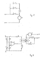
- Numbers 1 and 2 in Fig. 2 indicate two supply terminals on the electricity mains.
- To terminal 2 is connected one end of compressor 3 on a refrigerator with more than one cooling compartment.
- the other end of compressor 3 is connected to one end of defrosting resistor 4, placed in contact with the fresh food evaporator on the same refrigerator, and with one terminal of a mechanical thermostat 5 also placed on the fresh food evaporator of the same refrigerator.
- the other terminal of mechanical thermostat 5 is connected to terminal 1 on the electricity mains to which is also connected one end of any temperature-controlled switch element 6, or more specifically, a second mechanical thermostat, the other end of which is connected to the other end of defrosting resistor 4.
- a manual fast-freeze * switch 7 is connected parallel to the contacts on the second mechanical thermostat 6.
- the second mechanical thermostat 6 is placed on the fresh food evaporator but, in an alternative arrangement, it may also be placed inside the freezer compartment.
- thermostat 5 can be set by the operator within a minimum and maximum temperature range.
- the said thermostat 5 closes, when the evaporator it is placed on reaches maximum temperature (5°C) and opens when the said temperature falls to minimum (ranging from -17 to -25°C depending on the setting made by the operator).
- the temepra- ture-sensitive switch or second mecahnical thermostat 6, however, is set to one specific temperature when the device is assembled at the plant, e.g. -2°C (or -18.5°C in the case of the alternative arrangement with the thermostat inside the freezer).
- the said temperature-sensitive switch 6 is closed, when the temperature in the compartment it is assembled in is higher than the switch setting (-2°C; -18.5°C), and open when the said temperature is below the said setting.
- a refrigerator fitted with the present defrosting device operates as follows: when the temperature of the fresh food compartment evaporator rises to maximum (5°C), thermostat 5 closes and compressor 3 starts up to commence cooling. When the said temperature falls to minimum (-17 to -25°C), thermostat 5 opens to stop compressor 3. This is the point at which natural defrosting of the fresh food compartment evaporator commences, caused by the big difference in temperature between the evaporator itself, which is around -25°C, and the fresh food compartment, which is around 5°C.
- temperature-sensitive switch 6 closes and, as the contacts of thermostat 5 are open, supplies defrosting resistor 4 which supplies a large quantity of heat to the evaporator to raise the temperature rapidly and accelerate defrosting.
- thermostat 5 closes its contacts to short-circuit defrosting resistor 4, stop defrosting and start compressor 3 up again for another cooling cycle. With this operating mode, manual switch 7 is always open.
- defrosting resistor 4 For fast-freeze operation of the refrigerator, however, manual switch 7 is closed so that, whenever compressor 3 stops, defrosting resistor 4 is supplied so as to provide for fast defrosting so that another cooling cycle can be started immediately.
- a starting temperature of -2°C for defrosting resistor 4 was chosen for two reasons: 1) because of the small temperature difference between the evaporator and the fresh food compartment and consequently the low heat exchange possibility; 2) because, with -2°C on the fresh food compartment evaporator, the temperature inside the freezer is sure to be below -18°C. In any case, defrosting resistor 4 is powerful enough to complete defrosting before the temperature in the freezer exceeds the said maximum.
- the alternative arrangement of the present device provides for placing the temperature-sensitive switch 6 inside the freezer and for setting it to a temperature of -18.5°C.
- the said switch 6 will only close to supply defrosting resistor 4 when the temperature in the freezer rises to -18.5°C, thus avoiding all possible waste by only commencing a new cooling cycle when the said compartment requires it.
- defrosting resistor 4 will be powerful enough to ensure defrosting is completed before the freezer temperature reaches -18°C.
- Number 10 in Fig. 3 is a mains terminal to which is connected one end of compressor 11 on a refrigerator with more than one cooling compartment the other end of which is connected to one terminal of switch 12 and one anode (A,) of optotriac 13.
- the other end of switch 12 is connected to the other mains terminal 14 and to one end of defrosting resistor 15 on the fresh food compartment evaporator of the said refrigerator, the other end of which is connected to the other anode (A 2 ) of optotriac 13.
- Switch 12 is controlled by a known type of electronic circuit, not shown in the diagram, which may be of the type described in Italian Patent Application No. 68230-A/80 of July 3rd, 1980 filed by the present applicant.
- Number 16 is a resistor one end of which is connected to a positive d.c. supply (V) while the other end is connected to one end of a negative temperature coefficient (NTC) temperature sensor 17 the other end of which is grounded.
- the junction of resistor 16 and NTC 17 is connected to the non-inverting input of threshold voltage comparator 18.
- To the inverting input of the same threshold voltage comparator 18 is connected the junction of resistor 19, the other end of which goes to supply V, and resistor 20, the other end of which is grounded.
- the output of threshold voltage comparator 18 goes to the cathode of the emitting diode of optotriac 13 the anode of which is connected to one end of resistor 21 the other end of which goes to supply V.
- the cathode of the emitting diode of optotriac 13 is also connected to one terminal of a manual fast-freeze switch 22 the other terminal of which is grounded.
- NTC 17 is placed on the fresh food compartment evaporator and resistors 16, 19 and 20 designed so that the output of threshold voltage comparator 18 is high when the temperature of the fresh food compartment evaporator is below -2°C and low when the said temperature is over -2°C, that defrosting resistor 15 is not energized in the first case whereas it is in the second.
- NTC 17 is placed inside the freezer and resistors 16, 19 and 20 designed so that the output of threshold voltage comparator 18 is high when the temperature of the freezer is below -18.5°C and low when the said temperature is over -18.5°C.
- the defrosting device combining the present circuit and the one described in the abovementioned patent application has three temperature sensors, one on the fresh food compartment evaporator (9 in Fig. 2 of the abovementioned patent application), one inside the fresh food compartment (13 in Fig. 2 of the abovementioned patent application) and one inside the freezer 17.
- the defrosting device described operates as follows: as already stated, switch 12 is controlled by the circuit shown in Fig.
- the said defrosting resistor 15 must, of course, be powerful enough to complete the defrosting operation before the temperature in the freezer exceeds -18°C.
- hand switch 22 is closed so that optotriac 13 is always energized and defrosting resistor 15 always supplied whenever switch 12 is opened.
- the said resistor is more powerful than the one normally used in the known technique (e.g. 25 ⁇ 30 W as compared with 18 W) it completes defrosting faster, keeps compressor 11 running longer and freezes food faster than the known technique. If, during normal operation or fast freezing, the temperature of the fresh food compartment should fall below 0°C, switch 12 opens to commence natural defrosting, in the case of normal operation, or fast defrosting, in the case of fast freezing.
- a threshold of -2°C for commencing fast defrosting was selected because, from that point on, the difference in temperature between the fresh food compartment evaporator and the environment is very small and also because, with such a threshold, we can be certain the temperature in the freezer does not exceed -18°C. A situation could arise, however, in which, on account of low- load operation of the freezer or the fact that the freezer is left unopened for a long period of time, even with a temperature of -2°C on the fresh food compartment evaporator, the freezer does not need cooling in which case natural defrosting could be continued longer.
- a variation of the present defrosting device provides for placing NTC sensor 17 inside the freezer so that, after compressor 11 stops, natural defrosting continues until the temperature in the said freezer reaches -18.5°C. If this temperature is not reached before the temperature of the fresh food compartment evaporator reaches 5°C, a complete natural defrosting cycle would be performed, that is, with no help from defrosting resistor 15.
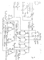
- the Fig. 4 circuit is a variation of the one shown in Fig. 3 whereby fast defrosting only takes place every "n" cycles.
- the said Figure shows: a threshold voltage comparator 30 with hysteresis whose inverting input is connected to one end of condenser 31, the other end of which is grounded (M 1 ), to one end of condenser 32, the other end of which goes to the non-inverting input of the same threshold voltage comparator 30, to one end of resistor 34, the other end of which is connected to (positive d.c.) supply V,, and to one end of negative temperature coefficient temperature sensor (NTC) 35, the other end of which is grounded (M l ).
- NTC negative temperature coefficient temperature sensor
- threshold comparator 30 is also connected to one end of condenser 36, the other end of which is grounded (M,), and to the middle terminal of potentiometer 37.
- One side terminal on potentiometer 37 is connected to one end of resistor 38, the other end of which goes to the cathode of diode 39, the anode of which is connected to the output of threshold voltage comparator 30.
- the other side terminal on potentiometer 37 goes to the junction of resistor 40, the other end of which is grounded (M,), and resistor 41, the other end of which goes to supply V i .
- the output of threshold voltage comparator 30 also goes to one end of condenser 42, the other end of which is grounded (M i ), to one end of resistor 43, the other end of which goes to supply V i , and to the non-inverting input of operational amplifier 44, the inverting input of which is connected to the junction of resistor 45, the other end of which is grounded (M i ), and resistor 46, the other end of which goes to supply V i .
- a hysteresis-free threshold voltage comparator 47 to whose inverting input are connected one end of condenser 48, the other end of which goes to the non-inverting input of the same threshold voltage comparator 47, and the junction of resistor 49, the other end of which goes to supply V 1 , and negative temperature coefficient (NTC) temperature sensor 50, the other end of which is grounded (M I ).
- the non-inverting input of threshold voltage comparator 47 is also connected to the junction of resistor 51, the other end of which goes to supply V 1 , and resistor 52, the other end of which is grounded (M I ). Via resistor 53, the output of threshold voltage comparator 47 goes to the junction of resistors 40 and 41.
- a hysteresis-free threshold voltage comparator 54 to whose inverting input is connected the junction of resistor 34 and temperature sensor 35 and to whose non-inverting input is connected the junction of resistor 55, the other end of which is grounded (M 1 ), and resistor 56, the other end of which goes to supply V I .
- Via resistor 57 the output of threshold voltage comparator 54 goes to supply V, and input "a" of NAND gate 58.
- the junction of resistor 34 and NTC sensor 35 is also connected to one end of resistor 59, the other end of which goes to the anode of diode 60, the cathode of which is connected to the output of NAND gate 58.
- the output of operational amplifier 44 goes to the cathode of an emitting diode on optotransistor 61 and to the clock (pin 114) of a decimal counter 62.
- the anode of the emitting diode on optotransistor 61 goes to supply V 1 via resistor 63.
- Via resistor 64 the collector of optotransistor 61 goes to supply V 2 (positive d.c. but separate from the V, supply).
- the emitter of optotransistor 61 goes to the base of NPN transistor 65, the emitter of which is grounded (M 2 ) (electrically apart from ground M i ).
- the circuit elements connected to terminals V 1 -M 1 and V 2 -M 2 are electrically separate and form two independent circuits, that is, with no electrical connections in common, therefore insulated as per safety standards.
- Via resistor 66 the collector of transistor 65 goes to supply V 2 and the gate of triac 67.
- One of the two anodes on triac 67 is grounded (M 2 ) while the other goes to one end of the windings on compressor 68, the other end of which goes to a terminal on the a.c. voltage electricity mains.
- Resistor 69 and condenser 70 are connected between the said two anodes on triac 67.
- the end of the winding on compressor 68 connected to triac 67 is also connected to one end of 18 W defrosting resistor 71, the other end of which is connected to an anode on triac 72.
- the other anode on triac 72 is connected to ground M 2 to which is also connected the other terminal on the a.c. voltage electricity mains.
- the gate of triac 72 is connected to the collector of PNP transistor 74, the emitter of which is connected to supply V 2 .
- the anode of the emitting diode on optotransistor 76 goes to supply V 1 , while the cathode goes to the anode of diode 78, to the anode of diode 79 and to the "b" input of NAND gate 58.
- the cathode of diode 78 is connected to the output of NAND gate 80, while the cathode of diode 79 is connected to the output of NAND gate 81.
- Input "b" of NAND gate 80 goes to one end of resistor 82 and to one end of condenser 83, the other end of which is grounded (M i ).
- the other end of resistor 82 goes to the output (pin 110) of decimal counter 62 which is also connected to input "b" of NAND gate 84. Inputs "a" of NAND gates 80, 81 and 84 are connected to supply V i .
- the output of NAND gate 84 goes to one end of condenser 85.
- the other end of condenser 85 goes to one end of resistor 86, the other end of which is grounded (M i ), to one end of condenser 87 and to the reset (pin 115) of counter 62.
- the other end of condenser 87 goes to supply V 1 , to the supply (pin 116) of counter 62 and to one end of condenser 88, the other end of which is grounded (M l ).
- NAND gate 81 is connected to the junction of one end of resistor 89, the other end of which goes to supply V i , and the anode of light emitting diode 90, the cathode of which goes to one end of resistor 91, the other end of which is grounded (M l ).
- the said input "b" of NAND gate 81 is also connected to one end of a manual switch 92, the other end of which is grounded (M i ).
- Manual switch 92 forms part of potentiometer 37. It is normally closed and is opened when the switch on the said potentiometer 37 is on the last setting.
- compressor 68 forms part of a refrigerating circuit with more than one refrigerating compartment, that NTC 35 is placed on the fresh food compartment evaporator and that NTC 50 is placed inside the fresh food compartment. Furthermore, we shall commence from fast defrosting of the fresh food compartment evaporator by defrosting resistor 71. When the temperature of the fresh food compartment evaporator (detected by NTC 35) reaches 5°C (defrosting over), the output of threshold voltage comparator 30 switches to high. Via operational amplifier 44, this voltage is transmitted to the cathode of the emitting diode on optotransistor 61 which stops conducting and so disables both optotransistor 61 and transistor 65. A positive signal is therefore sent to the gate of triac 67 which closes to start up compressor 68 and cool the refrigerator.
- NAND gate 58 As input “b" of the said gate is also logic 1, the output of NAND gate 58 will be low.
- the branch formed by resistor 59 and diode 60 (parallel to NTC 35) starts conducting and the voltage at the inverting input of threshold voltage comparator 30 is lowered to simulate the fresh food compartment evaporator reaching 5°C.
- a second pulse is thus sent to the clock on counter 62, which moves forward a second step, and a second cooling cycle is commenced. This is repeated for 4 cycles.
- a fifth pulse is sent to the clock on counter 62 which moves a fifth step forward and raises the voltage at its output (pin 110) so that a logic 1 is sent to inputs "b" of NAND gates 80 and 84.
- NAND gate 80 As input “a" of NAND gate 80 is also high, the output of the said NAND gate 80 switches to low, the emitting diode of optotransistor 76 starts conducting, optotransistor 76 and transistor 74 become saturated and a positive signal is sent to the gate of triac 72 which closes to enable the supply of defrosting resistor 71. At the same time, compressor 68 also receives the starting signal for commencing the fifth cooling cycle.
- the branch formed by counter 62, NAND gate 80, optotransistor 76, transistor 74 and triac 72 may be faster than the branch formed by optotransistor 61, transistor 65 and triac 67 so that a fast defrosting cycle via defrosting resistor 71 may be started instead of the fifth cooling cycle.
- the signal sent to input "b" of NAND gate 80 is delayed by resistor 82 and condenser 83 so that the fifth cooling cycle is sure to be started.
- triac 67 opens at the end of the fifth cooling cycle, as triac 72 is closed, defrosting resistor 71 is supplied and a fast defrosting cycle started and continued until the temperature of the fresh food compartment evaporator reaches 5°C.
- input "b" of NAND gate 58 is low so that the input of the same NAND gate 58 will be high, and, as the branch formed by resistor 59 and diode 60 is not conducting, threshold voltage comparator 30 switches when NTC 35 detects a temperature of 5°C.
- a sixth clock is sent to counter 62, which moves a sixth step forward, its pin 110 switches back to low and the logic 0 is sent to input "b" of NAND gate 84 (which was high).
- a positive pulse will be formed and transmitted, via condenser 85, to the reset (pin 115) of counter 62 which will be zeroed and start counting again from the beginning.
- this sixth clock pulse becomes the first clock pulse of a new set of cycles.
- Condenser 85 has been provided between the output of NAND gate 84 and the reset of counter 62 to "form" the reset pulse and ensure the said pulse is detected at all times by counter 62.
- the circuit described above provides for natural defrosting for four out of five cycles and fast defrosting, with the aid of defrosting resistor 71, for one out of five cycles.
- the natural defrosting cycles terminate when the temperature of the fresh food compartment evaporator reaches -2°C to avoid any danger of the temperature in the freezer exceeding -18°C.
- threshold voltage comparator 47 switches to low, the references at the non-inverting input of threshold voltage comparator 30 are changed and compressor 68 is stopped.
- threshold voltage comparator 54 could be connected to a branch comprising a temperature sensor inside the freezer and resistors 34, 55 and 56 could be set so that the output of threshold voltage comparator 54 switches to high when the temperature in the said freezer exceeds -18.5°C upwards. This arrangement would only start fast defrosting when the freezer actually needed it thus providing for further energy saving.
- triacs 13, 67 and 72 in the Fig. 3 and 4 circuits could be replaced by relay. Part list:
Landscapes
- Engineering & Computer Science (AREA)
- Chemical & Material Sciences (AREA)
- Combustion & Propulsion (AREA)
- Physics & Mathematics (AREA)
- Mechanical Engineering (AREA)
- Thermal Sciences (AREA)
- General Engineering & Computer Science (AREA)
- Defrosting Systems (AREA)
Claims (38)
Applications Claiming Priority (2)
| Application Number | Priority Date | Filing Date | Title |
|---|---|---|---|
| IT67519/82A IT1155313B (it) | 1982-04-20 | 1982-04-20 | Dispositivo di sbrinamento per un apparecchio frigorifero |
| IT6751982 | 1982-04-20 |
Publications (3)
| Publication Number | Publication Date |
|---|---|
| EP0092089A2 EP0092089A2 (de) | 1983-10-26 |
| EP0092089A3 EP0092089A3 (en) | 1984-08-29 |
| EP0092089B1 true EP0092089B1 (de) | 1988-12-14 |
Family
ID=11303109
Family Applications (1)
| Application Number | Title | Priority Date | Filing Date |
|---|---|---|---|
| EP83103255A Expired EP0092089B1 (de) | 1982-04-20 | 1983-04-01 | Abtauvorrichtung für einen Kühlschrank |
Country Status (5)
| Country | Link |
|---|---|
| US (1) | US4530217A (de) |
| EP (1) | EP0092089B1 (de) |
| DE (1) | DE3378694D1 (de) |
| ES (1) | ES521676A0 (de) |
| IT (1) | IT1155313B (de) |
Families Citing this family (15)
| Publication number | Priority date | Publication date | Assignee | Title |
|---|---|---|---|---|
| JP2562639B2 (ja) * | 1988-01-20 | 1996-12-11 | 三洋電機株式会社 | 低温商品貯蔵ケースの温度制御方式 |
| US4974418A (en) * | 1988-10-12 | 1990-12-04 | Honeywell Inc. | Heat pump defrosting operation |
| US4974417A (en) * | 1988-10-12 | 1990-12-04 | Honeywell Inc. | Heat pump defrosting operation |
| US4951473A (en) * | 1988-10-12 | 1990-08-28 | Honeywell, Inc. | Heat pump defrosting operation |
| US5201888A (en) * | 1991-11-14 | 1993-04-13 | White Consolidated Industries, Inc. | Temperature control system for refrigerator/freezer combinations |
| DE4438917C2 (de) * | 1994-11-03 | 1998-01-29 | Danfoss As | Verfahren zum Abtauen eines Kältesystems und Steuergerät zur Durchführung dieses Verfahrens |
| US5842355A (en) * | 1995-03-22 | 1998-12-01 | Rowe International, Inc. | Defrost control system for a refrigerator |
| US5924297A (en) * | 1997-11-03 | 1999-07-20 | Hussmann Corporation | Refrigerated merchandiser with modular evaporator coils and "no defrost" product area |
| JP3888403B2 (ja) * | 1997-12-18 | 2007-03-07 | 株式会社富士通ゼネラル | 空気調和機の制御方法およびその装置 |
| NZ503106A (en) * | 2000-02-28 | 2002-07-26 | Fisher & Paykel Appliances Ltd | Refrigerator with at least a fresh food compartment and evaporator operating within 10 degrees centigrade below compartment temperature, so that air at above 0 degrees is blown over evaporator during off cycle |
| US6817195B2 (en) * | 2002-03-29 | 2004-11-16 | General Electric Company | Reduced energy refrigerator defrost method and apparatus |
| US8417386B2 (en) * | 2008-11-17 | 2013-04-09 | Trane International Inc. | System and method for defrost of an HVAC system |
| WO2011041780A2 (en) * | 2009-10-02 | 2011-04-07 | The Controls Group, Inc. | Removal of an accumulated frozen substance from a cooling unit |
| US8291718B2 (en) * | 2010-09-02 | 2012-10-23 | General Electric Company | DSM defrost during high demand |
| JP5897994B2 (ja) * | 2012-06-06 | 2016-04-06 | シャープ株式会社 | 空気調和機 |
Citations (1)
| Publication number | Priority date | Publication date | Assignee | Title |
|---|---|---|---|---|
| FR2164789A1 (de) * | 1971-12-23 | 1973-08-03 | Philips Nv |
Family Cites Families (12)
| Publication number | Priority date | Publication date | Assignee | Title |
|---|---|---|---|---|
| US2130036A (en) * | 1934-07-21 | 1938-09-13 | John A Shrader | Defroster |
| US2720086A (en) * | 1953-08-13 | 1955-10-11 | Gen Electric | Automatic defrosting systems for twotemperature refrigerators |
| US2867093A (en) * | 1955-12-20 | 1959-01-06 | Gen Motors Corp | Defrosting arrangement for refrigerating system |
| CH413880A (de) * | 1964-11-23 | 1966-05-31 | Forster Ag Hermann | Kühlschrank |
| US3553975A (en) * | 1967-08-07 | 1971-01-12 | Sanyo Electric Co | Refrigerator temperature and defrosting control |
| DE2010717A1 (de) * | 1970-03-06 | 1971-09-23 | Necchi Societä per Azioni, Pavia (Italien) | Schmiervorrichtung für gekapselte Motor-Verdichter-Aggregate |
| AT325644B (de) * | 1973-10-11 | 1975-10-27 | Bosch Hausgeraete Gmbh | Kühlmöbel, insbesondere zweitemperaturen-kühlschrank |
| DE2557794A1 (de) * | 1975-12-22 | 1977-06-23 | Licentia Gmbh | Verfahren und vorrichtung zum abtauen des verdampfers bei einem kuehlgeraet mit abtauvorrichtung |
| DE2629595A1 (de) * | 1976-07-01 | 1978-01-05 | Licentia Gmbh | Verfahren und vorrichtung zum abtauen des verdampfers bei einem kuehlgeraet mit abtauvorrichtung |
| DE2753744C3 (de) * | 1977-12-02 | 1981-11-19 | Bosch-Siemens Hausgeräte GmbH, 7000 Stuttgart | Gefriergerät, insbesondere Gefrierschrank, Gefriertruhe o.dgl. mit Abtauvorrichtung |
| US4299095A (en) * | 1979-08-13 | 1981-11-10 | Robertshaw Controls Company | Defrost system |
| US4305259A (en) * | 1980-04-03 | 1981-12-15 | Eaton Corporation | Frost sensor employing self-heating thermistor as sensor element |
-
1982
- 1982-04-20 IT IT67519/82A patent/IT1155313B/it active
-
1983
- 1983-04-01 DE DE8383103255T patent/DE3378694D1/de not_active Expired
- 1983-04-01 EP EP83103255A patent/EP0092089B1/de not_active Expired
- 1983-04-19 US US06/486,369 patent/US4530217A/en not_active Expired - Fee Related
- 1983-04-20 ES ES521676A patent/ES521676A0/es active Granted
Patent Citations (1)
| Publication number | Priority date | Publication date | Assignee | Title |
|---|---|---|---|---|
| FR2164789A1 (de) * | 1971-12-23 | 1973-08-03 | Philips Nv |
Also Published As
| Publication number | Publication date |
|---|---|
| IT8267519A1 (it) | 1983-10-20 |
| ES8404043A1 (es) | 1984-04-01 |
| IT1155313B (it) | 1987-01-28 |
| US4530217A (en) | 1985-07-23 |
| DE3378694D1 (en) | 1989-01-19 |
| ES521676A0 (es) | 1984-04-01 |
| EP0092089A3 (en) | 1984-08-29 |
| IT8267519A0 (it) | 1982-04-20 |
| EP0092089A2 (de) | 1983-10-26 |
Similar Documents
| Publication | Publication Date | Title |
|---|---|---|
| EP0092089B1 (de) | Abtauvorrichtung für einen Kühlschrank | |
| KR860002043B1 (ko) | 제상장치 | |
| US4173871A (en) | Refrigeration apparatus demand defrost control system and method | |
| US6138465A (en) | Method for controlling the temperature of a refrigeration unit and temperature control arrangement for a refrigeration unit | |
| US20040244389A1 (en) | Integrated refrigeration control | |
| JP3424924B2 (ja) | 冷蔵庫の除霜ヒータ制御方法 | |
| US4056948A (en) | Presettable defrost timer | |
| US2545054A (en) | Refrigerator control | |
| EP0045728B1 (de) | Elektronischer Temperaturregler für ein Gefriergerät | |
| US4530218A (en) | Refrigeration apparatus defrost control | |
| US4086780A (en) | Refrigerating apparatus, in particular two-temperature refrigerator | |
| US3367128A (en) | Control system for ice-making apparatus | |
| US4344295A (en) | Control for timed operation of ice maker | |
| US3277662A (en) | Refrigeration system defrost control | |
| US20100242506A1 (en) | Evaporator fan motor control in a refrigerated merchandiser | |
| EP1325271B1 (de) | Verfahren zur steuerung eines kältegerätes | |
| CN220291481U (zh) | 一种电气机柜自动分级散热结构 | |
| US3483919A (en) | Electric refrigerator with defrosting means | |
| EP0388726B1 (de) | Kühlgerät mit nur einer thermostatischen Temperaturregelvorrichtung | |
| US3918267A (en) | Ice-maker control circuit with slab limiting control | |
| GB2100031A (en) | Electrical control circuit for refrigerators and freezers | |
| CN109539686B (zh) | 冰箱控制装置及冰箱 | |
| JPH0230706Y2 (de) | ||
| US2231628A (en) | Defroster | |
| JPS5914702Y2 (ja) | 解凍装置付冷凍冷蔵庫の制御装置 |
Legal Events
| Date | Code | Title | Description |
|---|---|---|---|
| PUAI | Public reference made under article 153(3) epc to a published international application that has entered the european phase |
Free format text: ORIGINAL CODE: 0009012 |
|
| AK | Designated contracting states |
Designated state(s): DE FR GB NL SE |
|
| PUAL | Search report despatched |
Free format text: ORIGINAL CODE: 0009013 |
|
| AK | Designated contracting states |
Designated state(s): DE FR GB NL SE |
|
| 17P | Request for examination filed |
Effective date: 19850219 |
|
| GRAA | (expected) grant |
Free format text: ORIGINAL CODE: 0009210 |
|
| AK | Designated contracting states |
Kind code of ref document: B1 Designated state(s): DE FR GB NL SE |
|
| RAP2 | Party data changed (patent owner data changed or rights of a patent transferred) |
Owner name: INDESIT - S.R.L. |
|
| REF | Corresponds to: |
Ref document number: 3378694 Country of ref document: DE Date of ref document: 19890119 |
|
| ET | Fr: translation filed | ||
| PLBE | No opposition filed within time limit |
Free format text: ORIGINAL CODE: 0009261 |
|
| STAA | Information on the status of an ep patent application or granted ep patent |
Free format text: STATUS: NO OPPOSITION FILED WITHIN TIME LIMIT |
|
| 26N | No opposition filed | ||
| EAL | Se: european patent in force in sweden |
Ref document number: 83103255.2 |
|
| PGFP | Annual fee paid to national office [announced via postgrant information from national office to epo] |
Ref country code: NL Payment date: 19950430 Year of fee payment: 13 |
|
| PGFP | Annual fee paid to national office [announced via postgrant information from national office to epo] |
Ref country code: FR Payment date: 19950503 Year of fee payment: 13 |
|
| PGFP | Annual fee paid to national office [announced via postgrant information from national office to epo] |
Ref country code: GB Payment date: 19950505 Year of fee payment: 13 |
|
| PGFP | Annual fee paid to national office [announced via postgrant information from national office to epo] |
Ref country code: SE Payment date: 19950510 Year of fee payment: 13 |
|
| PGFP | Annual fee paid to national office [announced via postgrant information from national office to epo] |
Ref country code: DE Payment date: 19950517 Year of fee payment: 13 |
|
| PG25 | Lapsed in a contracting state [announced via postgrant information from national office to epo] |
Ref country code: GB Effective date: 19960401 |
|
| PG25 | Lapsed in a contracting state [announced via postgrant information from national office to epo] |
Ref country code: SE Effective date: 19960402 |
|
| PG25 | Lapsed in a contracting state [announced via postgrant information from national office to epo] |
Ref country code: NL Effective date: 19961101 |
|
| GBPC | Gb: european patent ceased through non-payment of renewal fee |
Effective date: 19960401 |
|
| PG25 | Lapsed in a contracting state [announced via postgrant information from national office to epo] |
Ref country code: FR Effective date: 19961227 |
|
| PG25 | Lapsed in a contracting state [announced via postgrant information from national office to epo] |
Ref country code: DE Effective date: 19970101 |
|
| NLV4 | Nl: lapsed or anulled due to non-payment of the annual fee |
Effective date: 19961101 |
|
| EUG | Se: european patent has lapsed |
Ref document number: 83103255.2 |
|
| REG | Reference to a national code |
Ref country code: FR Ref legal event code: ST |