EP0092231A1 - Circuit d'excitation pour dispositifs laser, en particulier pour laser à haute énergie du type TE, avec ajustement de pré-ionisation - Google Patents
Circuit d'excitation pour dispositifs laser, en particulier pour laser à haute énergie du type TE, avec ajustement de pré-ionisation Download PDFInfo
- Publication number
- EP0092231A1 EP0092231A1 EP83103776A EP83103776A EP0092231A1 EP 0092231 A1 EP0092231 A1 EP 0092231A1 EP 83103776 A EP83103776 A EP 83103776A EP 83103776 A EP83103776 A EP 83103776A EP 0092231 A1 EP0092231 A1 EP 0092231A1
- Authority
- EP
- European Patent Office
- Prior art keywords
- circuit
- pulse
- laser
- pfn
- ionization
- Prior art date
- Legal status (The legal status is an assumption and is not a legal conclusion. Google has not performed a legal analysis and makes no representation as to the accuracy of the status listed.)
- Granted
Links
- 230000005284 excitation Effects 0.000 title claims description 24
- 239000003990 capacitor Substances 0.000 claims abstract description 20
- 239000004020 conductor Substances 0.000 claims abstract description 18
- 101100084409 Caenorhabditis elegans pfn-1 gene Proteins 0.000 claims abstract description 13
- 101100353414 Caenorhabditis elegans pfn-2 gene Proteins 0.000 claims description 12
- 238000010278 pulse charging Methods 0.000 claims description 7
- 238000007600 charging Methods 0.000 claims description 3
- 230000015556 catabolic process Effects 0.000 claims description 2
- XLYOFNOQVPJJNP-UHFFFAOYSA-N water Substances O XLYOFNOQVPJJNP-UHFFFAOYSA-N 0.000 claims description 2
- 102100020720 Calcium channel flower homolog Human genes 0.000 claims 3
- 101000932468 Homo sapiens Calcium channel flower homolog Proteins 0.000 claims 3
- 230000004913 activation Effects 0.000 claims 2
- 238000010891 electric arc Methods 0.000 claims 1
- 239000007788 liquid Substances 0.000 claims 1
- 230000003287 optical effect Effects 0.000 claims 1
- 101000577619 Homo sapiens Profilin-1 Proteins 0.000 abstract description 3
- 102100028857 Profilin-1 Human genes 0.000 abstract description 3
- 230000037452 priming Effects 0.000 abstract 1
- 238000010586 diagram Methods 0.000 description 6
- 230000008878 coupling Effects 0.000 description 1
- 238000010168 coupling process Methods 0.000 description 1
- 238000005859 coupling reaction Methods 0.000 description 1
- 238000011161 development Methods 0.000 description 1
- 230000018109 developmental process Effects 0.000 description 1
- 238000005265 energy consumption Methods 0.000 description 1
- 238000000034 method Methods 0.000 description 1
Images


Classifications
-
- H—ELECTRICITY
- H01—ELECTRIC ELEMENTS
- H01S—DEVICES USING THE PROCESS OF LIGHT AMPLIFICATION BY STIMULATED EMISSION OF RADIATION [LASER] TO AMPLIFY OR GENERATE LIGHT; DEVICES USING STIMULATED EMISSION OF ELECTROMAGNETIC RADIATION IN WAVE RANGES OTHER THAN OPTICAL
- H01S3/00—Lasers, i.e. devices using stimulated emission of electromagnetic radiation in the infrared, visible or ultraviolet wave range
- H01S3/09—Processes or apparatus for excitation, e.g. pumping
- H01S3/097—Processes or apparatus for excitation, e.g. pumping by gas discharge of a gas laser
- H01S3/0971—Processes or apparatus for excitation, e.g. pumping by gas discharge of a gas laser transversely excited
- H01S3/09713—Processes or apparatus for excitation, e.g. pumping by gas discharge of a gas laser transversely excited with auxiliary ionisation, e.g. double discharge excitation
Definitions
- the invention relates to an excitation circuit for laser systems, in particular for TE high-energy lasers, according to the preamble of claim 1.
- Such an excitation circle has been proposed, for example, in the earlier application P 31 28 206.7 of July 16, 1981 and is known from DE-OS 29 32 781, however, without showing pre-ionization devices.
- Suitable pre-ionization devices are known, for example, from DE-OS 30 35 702 with sliding discharge paths and from DE-OS 30 35 730 with pre-ionization rods.
- DE-OS 30 35 702 with sliding discharge paths
- DE-OS 30 35 730 with pre-ionization rods.
- the time of use of the pre-ionization is namely to be coordinated with any laser system, for example KrF, XeCl, XeF or C0 2 , and for cost reasons the pre-ionization should be able to be carried out with as little effort as possible and with low energy requirements.
- the invention has for its object to provide an excitation circuit for laser systems with the associated pre-ionization device so that it takes into account the aforementioned requirements in a particularly effective manner, i.e., in which the effort of circuit measures can be kept low.
- the object is achieved in the main with an excitation circuit for laser systems according to the generic term by the features specified in the characterizing part of claim 1.
- the invention is suitable both for sliding spark gaps as pre-ionization devices and for pre-ionization devices which work with ignition electrodes which are arranged with a small flashover distance, in particular axially parallel to the elongated laser electrodes, in particular as so-called pre-ionization bars are each assigned to one of the opposing laser electrodes.
- an effective pre-ionization device for the operation of TE lasers, an effective pre-ionization device, as described, for example, in P 30 35 702.9 and P 30 35 730.3, is of particular importance.
- the time of use of the pre-ionization is to be coordinated with any laser system, for example KrF, XeCl, XeF or C0 2 , and for cost reasons the pre-ionization should be able to be carried out with as little effort as possible and with low energy consumption.
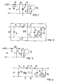
- Fig. 1 shows the basic electrical connection of a pre-ionization device VE, as described in P 30 35 702.9.
- C 1 , C 2 are capacitors of a BlUmlein circuit
- G is the sliding spark gap with the two poles g
- S is a switching element, for example a spark gap.
- the circuit is connected to the high-voltage supply HV via the inductor L v or a resistor R V (shown in dashed lines as an alternative).
- R o is a high-impedance impedance, in particular a resistor, which is connected in parallel to the sliding spark gap G. High-resistance means high-resistance in comparison to the resistance of the ignited sliding spark gap G.
- FIG. 2 shows the circuit diagram of a TE laser in which the Blümlein circuit is used as the pulse-forming network and the capacitors are charged by the high voltage HV, as is required when water is used as the dielectric.
- the laser electrodes of the laser chamber LK are denoted by E L , the high-impedance impedance, in particular a resistor, connected in parallel to the laser discharge path, with R K , the stripline capacitors with C Ft C K ; the high-voltage switch with S L , the earth potential rail of the pulse-forming network works PFN 1 with B and the circuit elements of the pulse charging capacity, the pulse switch and the series inductance with Cp, Sp and Lp connected to this at the input of the pulse-forming network PFN1.
- the high-voltage supply for the pre-ionization can expediently be tapped at points A or A * or A ', where A is between Sp and Lp at the input of PFN1 on the high-voltage side, A * at the high branch point to the high-voltage switch S L and, on the one hand, a strip conductor capacitor C F and A 'directly on the supply line of the high-lying laser electrode E L.
- the capacitors C 1 , C 2 are charged while the voltage is applied to the laser electrodes.
- the sliding spark gap G breaks through in this variant after the switch S L has been ignited, the point in time being able to be predetermined by setting the ignition voltage of the switch S.
- the capacitance C 1 is omitted in comparison to FIG. 1; C corresponds to the capacitance C 2 and R 1 to the impedance R o .
- the point in time of the pre-ionization is controlled in accordance with the auxiliary circuit HS1 according to FIG. 1.
- a charge transfer circuit PFN 2 as shown in FIG. 4, is used as the pulse-forming network for the laser circuit, the measures described for pre-ionization control can be applied analogously.
- the same parts as in FIG. 2 have the same reference numerals.
- FIG. 5 shows the pulse-forming network PFN 1 according to Fig. 2 and the rest of the circuit for the pre-ionization according to P 30 35 730. 3, with a Blümlein circuit used as the PFN for the laser circuit and, for the sake of simplicity, only one auxiliary electrode each Preionization device VE, H is drawn, which is assigned to a laser electrode E L.
- FIG. 6 shows the same basic arrangement of the pre-ionization device VE, H with a charge transfer circuit as the pulse-forming network PFN 2 of the laser, the same parts again having the same reference numerals, cf. also Fig. 4.
- FIG. 7 shows on the basis of an auxiliary circuit HS 3, which consists of two auxiliary circuit halves of the same type for each electrode E L , which allows the ignition timing of the pre-ionization to be shifted out.
- Small spark gaps F for example surge arresters, are inserted into the leads of the inner conductors of the ignition electrodes or pre-ionization rods h, which can be bridged by small capacitances C '.
- the potential of the inner conductor remains almost at the potential of the neighboring electrode due to the capacitive coupling of the inner conductor of the ignition electrode with the adjacent electrode E L (see rollover distance ü), so that a potential difference is formed on both electrodes of the spark gap F. .
- the full potential difference between the inner conductor of the ignition electrode h and the neighboring electrode E L is only present when the spark gap is broken.
- the time of the pre-ionization can be shifted by varying the breakdown voltage of the spark gap F.
- This auxiliary circuit HS 3 is connected directly to node A ', cf. 5 and 6.
- FIG. 8 describes an auxiliary circuit HS 4, which makes it possible to pre-ionize before closing the switch S L of the pulse-forming network PFN 1 or PFN 2.
- the capacitor C o ' is charged from point A * of the pulse charging device via an impedance R V1 , which is designed as a capacitor, inductance or ohmic resistor.
- R V1 is designed as a capacitor, inductance or ohmic resistor.
- the high-impedance R 2 lies parallel to the discharge path h - E L , and the series connection of C o and F is connected in parallel to this parallel connection, the pulse voltage being supplied via R v1 at the connection point between C o and F.
- A can also be selected as the connection point if the ignition pulse for VE should come sooner.
- the two halves of the auxiliary circuit HS 4 also correspond to the circuit HS 2.
- a variation of the circuit according to FIG. 8 consists in connecting the inner conductor of the ignition electrode h directly to the points A * or A (FIG. 8a).
- FIG. 9 shows a variant of the auxiliary circuit HS 4 according to FIG. 8.
- This auxiliary circuit HS 6 allows a higher potential difference to be achieved between the inner conductor of the ignition electrode and the adjacent electrode E L , the pre-ionization also being used in the arrangement in FIG. 9 before the switch S L is closed.
- the auxiliary circuit halves are designed as Blümlein circuits; the circuit elements corresponding to the circuit elements R 0 , C 1 , C 2 and S according to FIG. 1 are denoted by R 3 , C 2 , C * and F.
- the auxiliary circuit HS 7 shown in FIG. 10 allows the pre-ionization to be set to a point in time after the switch S L is closed .
- the capacitance C3 is charged via an impedance R V3 (capacitance, inductance or ohmic resistance) until the spark gap F breaks through.
- R V3 impedance, inductance or ohmic resistance
- Fig. 8 shows that in the auxiliary circuit HS 7, the circuit elements R 4 , F, C3 and R V3 correspond to the circuit elements R 29 F, C 0 and R V1 according to Fig. 8 (HS 4), but the Lines containing ballast impedance R v3 are not connected to A or A * , but to A'or B respectively.
- the auxiliary circuit HS 8 shown in FIG. 11 allows a higher voltage to be achieved than HS 7.
- FIG. 11 the auxiliary circuit halves of the pre-ionization device VE, H are again based on a Blümlein circuit, as can be seen from a comparison with FIG. 9.
- the circuit elements corresponding to the circuit elements R 3 , C 1 , C 2 , F and R v2 according to FIG. 9 are designated in FIG. 11 with R 5 , C 4 , C 5 , F and R v4 .
- the branches with R v4 are connected to A 'or B instead of being connected to A or A * corresponding to FIG. 10.
- the L, C values L 20 , C 20 of the auxiliary circuit which is used to couple the sliding spark gap G to the main circuit, are small or very small compared to the L, C values in the main discharge circuit of the laser, that is to say to the C values of the strip conductor capacitors C K and C F and to the L values of the impedance R K and to other inductances contained in the main discharge circuit, which in particular result from the self-inductance of the laser head, the feed lines and the strip conductor capacitors and which are symbolized by the equivalent inductance L 10 . Due to the smaller LC values of the auxiliary circuit HS 9, the preionization device according to FIG.
- auxiliary circuit HS 10 works faster than the main discharge.
- R V10 is an impedance or a resistor which is connected in parallel with the sliding spark gap G, g and which has a high resistance compared to the resistance value of the ignited sliding spark gap F, g.
- the auxiliary circuit HS 9 according to FIG. 12 is a series resonant circuit which is connected in series with the sliding spark gap and which is connected to the switching point A * .
- the auxiliary circuit HS 9 to the auxiliary circuit HS 10, a Blümlein circuit is supplemented by the parallel capacitance C 10 , the connection point of the auxiliary circuit with respect to A * being the inner end of the inductor L 20 and its outer end connected to the two g un g L 10 - S L is connected.
- FIG. 14 shows further variations, in which the main discharge circuit is based on a charge transfer circuit.
- the auxiliary circuit according to FIG. 14, which corresponds to that according to FIG. 12, has been supplemented according to FIG. 15 to a Blümlein circuit corresponding to FIG. 13.
- the switching element S L of the pulse-forming networks PFN 1 (Blümlein circuit) or PFN 2 (charge transfer circuit) as a switching element of the pre-ionization auxiliary circuits HS 9 to HS 12 is also used.
- the dimensions of the circuit elements L 209 C 20 ' C 10 of the auxiliary circuits HS 9 to HS 12 required for the timely ignition of the sliding spark gaps G are given in relation to the circuit elements L 10 , C F , C K of the main circuit by inequalities.
- These auxiliary circuits are particularly suitable for C0 2 lasers, in which a less rapid response of the pre-ionization devices is required, such as with excimer lasers.
- FIG. 16 shows a diagram to illustrate the possible point in time for the ignition of the pre-ionization devices VE depending on the connection of their auxiliary circuits to the circuit points A, A * or A '. Everything else is clear from the explanations of the diagram. It has proven to be advantageous if the preionization bars VE, H, HS 3 to HS 8, which have preionization bars h, operate according to the principle of the corona discharge and for this purpose consist of a rod-shaped, electrically conductive electrode core and an insulating dielectric jacket.
Landscapes
- Physics & Mathematics (AREA)
- Electromagnetism (AREA)
- Engineering & Computer Science (AREA)
- Plasma & Fusion (AREA)
- Optics & Photonics (AREA)
- Lasers (AREA)
Priority Applications (1)
| Application Number | Priority Date | Filing Date | Title |
|---|---|---|---|
| AT83103776T ATE16223T1 (de) | 1982-04-19 | 1983-04-19 | Anregungskreis fuer lasersysteme, insbesondere fuer te-hochenergielaser, mit einstellung der vorionisierung. |
Applications Claiming Priority (2)
| Application Number | Priority Date | Filing Date | Title |
|---|---|---|---|
| DE3214333 | 1982-04-19 | ||
| DE3214333 | 1982-04-19 |
Publications (2)
| Publication Number | Publication Date |
|---|---|
| EP0092231A1 true EP0092231A1 (fr) | 1983-10-26 |
| EP0092231B1 EP0092231B1 (fr) | 1985-10-23 |
Family
ID=6161233
Family Applications (1)
| Application Number | Title | Priority Date | Filing Date |
|---|---|---|---|
| EP83103776A Expired EP0092231B1 (fr) | 1982-04-19 | 1983-04-19 | Circuit d'excitation pour dispositifs laser, en particulier pour laser à haute énergie du type TE, avec ajustement de pré-ionisation |
Country Status (4)
| Country | Link |
|---|---|
| EP (1) | EP0092231B1 (fr) |
| JP (1) | JPS59500591A (fr) |
| AT (1) | ATE16223T1 (fr) |
| WO (1) | WO1983003720A1 (fr) |
Cited By (2)
| Publication number | Priority date | Publication date | Assignee | Title |
|---|---|---|---|---|
| WO1997025759A1 (fr) * | 1996-01-05 | 1997-07-17 | Boris Vasilievich Lazhintsev | Dispositif d'electrodes permettant la formation d'une decharge volumetrique auto-entretenue |
| RU2212083C1 (ru) * | 2002-05-15 | 2003-09-10 | Федеральное государственное унитарное предприятие "Научно-исследовательский институт электрофизической аппаратуры им. Д.В.Ефремова" | Устройство накачки широкоапертурного газового лазера или усилителя высокого давления |
Families Citing this family (4)
| Publication number | Priority date | Publication date | Assignee | Title |
|---|---|---|---|---|
| FR2579382B1 (fr) * | 1985-03-22 | 1987-06-05 | Saint Louis Inst | Dispositif d'alimentation d'un tube laser |
| JPS62282476A (ja) * | 1986-05-30 | 1987-12-08 | Mitsubishi Electric Corp | レ−ザ装置 |
| EP0402417A1 (fr) * | 1988-04-25 | 1990-12-19 | Siemens Aktiengesellschaft | Dispositif de pre-ionisation de lasers a gaz pompes par decharge, notamment pour la pre-ionisation par rayons x |
| RU2141708C1 (ru) * | 1998-03-10 | 1999-11-20 | Государственное предприятие "Научно-исследовательский институт электрофизической аппаратуры им.Д.В.Ефремова" | Устройство накачки мощного импульсно-периодического газового лазера |
Citations (4)
| Publication number | Priority date | Publication date | Assignee | Title |
|---|---|---|---|---|
| EP0048407A1 (fr) * | 1980-09-22 | 1982-03-31 | Kraftwerk Union Aktiengesellschaft | Laser TEA à haute énergie avec barres d'ionisation parallèles à l'axe du laser |
| DE3035702A1 (de) * | 1980-09-22 | 1982-04-29 | Kraftwerk Union AG, 4330 Mülheim | Vorionisierungs-anordnung fuer tea-laser, insbesondere tea-excimmer-laser |
| DE3128206A1 (de) * | 1981-07-16 | 1983-01-27 | Kraftwerk Union AG, 4330 Mülheim | Bandleiterkondensator zur energiespeicherung, vorzugsweise fuer hochenergielaser |
| EP0024576B1 (fr) * | 1979-08-13 | 1984-07-25 | Kraftwerk Union Aktiengesellschaft | Dispositif pour la production de décharges pulsées rapides dans un laser, notamment pour des lasers à haute energie |
-
1983
- 1983-04-19 JP JP83501344A patent/JPS59500591A/ja active Pending
- 1983-04-19 EP EP83103776A patent/EP0092231B1/fr not_active Expired
- 1983-04-19 AT AT83103776T patent/ATE16223T1/de not_active IP Right Cessation
- 1983-04-19 WO PCT/DE1983/000072 patent/WO1983003720A1/fr not_active Ceased
Patent Citations (4)
| Publication number | Priority date | Publication date | Assignee | Title |
|---|---|---|---|---|
| EP0024576B1 (fr) * | 1979-08-13 | 1984-07-25 | Kraftwerk Union Aktiengesellschaft | Dispositif pour la production de décharges pulsées rapides dans un laser, notamment pour des lasers à haute energie |
| EP0048407A1 (fr) * | 1980-09-22 | 1982-03-31 | Kraftwerk Union Aktiengesellschaft | Laser TEA à haute énergie avec barres d'ionisation parallèles à l'axe du laser |
| DE3035702A1 (de) * | 1980-09-22 | 1982-04-29 | Kraftwerk Union AG, 4330 Mülheim | Vorionisierungs-anordnung fuer tea-laser, insbesondere tea-excimmer-laser |
| DE3128206A1 (de) * | 1981-07-16 | 1983-01-27 | Kraftwerk Union AG, 4330 Mülheim | Bandleiterkondensator zur energiespeicherung, vorzugsweise fuer hochenergielaser |
Non-Patent Citations (5)
| Title |
|---|
| APPLIED PHYSICS LETTERS, Band 37, Nr. 10, 15. November 1980, Seiten 883-885, American Institute of Physics, New York, USA * |
| APPLIED PHYSICS LETTERS, Band 37, Nr. 9, 1. November 1980, Seiten 771-773, New York, USA * |
| APPLIED PHYSICS LETTERS, Band 38, Nr. 1, 1. Januar 1981, Seiten 3-6, American Institute of Physics, New York, USA * |
| JAPANESE JOURNAL OF APPLIED PHYSICS, Band 20, Nr. 1, Januar 1981, Seiten 129-137, Tokyo, JP. * |
| REVIEW OF SCIENTIFIC INSTRUMENTS, Band 47, Nr. 5, Mai 1976, Seiten 608-613, American Institute of Physics, New York, USA * |
Cited By (2)
| Publication number | Priority date | Publication date | Assignee | Title |
|---|---|---|---|---|
| WO1997025759A1 (fr) * | 1996-01-05 | 1997-07-17 | Boris Vasilievich Lazhintsev | Dispositif d'electrodes permettant la formation d'une decharge volumetrique auto-entretenue |
| RU2212083C1 (ru) * | 2002-05-15 | 2003-09-10 | Федеральное государственное унитарное предприятие "Научно-исследовательский институт электрофизической аппаратуры им. Д.В.Ефремова" | Устройство накачки широкоапертурного газового лазера или усилителя высокого давления |
Also Published As
| Publication number | Publication date |
|---|---|
| ATE16223T1 (de) | 1985-11-15 |
| JPS59500591A (ja) | 1984-04-05 |
| EP0092231B1 (fr) | 1985-10-23 |
| WO1983003720A1 (fr) | 1983-10-27 |
Similar Documents
| Publication | Publication Date | Title |
|---|---|---|
| DE69629422T2 (de) | Hochspannungsimpulsgenerator | |
| DE3314157A1 (de) | Anregungskreis fuer lasersysteme, insbesondere fuer te-hochenergielaser, mit einstellung der vorionisierung | |
| DE3705165C2 (fr) | ||
| WO1989010657A1 (fr) | Procede et dispositif generateur d'impulsions de haute tension et de haute puissance, notamment pour lasers a gaz a decharge partielle | |
| DE102007046902A1 (de) | Impulsspannungsgenerator sowie Stoßwellentherapievorrichtung mit einem Impulsspannungsgenerator | |
| EP0024576A1 (fr) | Dispositif pour la production de décharges pulsées rapides dans un laser, notamment pour des lasers à haute energie | |
| EP0108299B1 (fr) | Système d'excitation pour créer une décharge impulsionnelle rapide à haute tension en particulier pour exciter un laser à haute performance | |
| DE19541031A1 (de) | Gepulste Laservorrichtung mit Entladungsanregung | |
| EP0092231B1 (fr) | Circuit d'excitation pour dispositifs laser, en particulier pour laser à haute énergie du type TE, avec ajustement de pré-ionisation | |
| WO1989010645A1 (fr) | Agencement de pre-ionisation, notamment de pre-ionisation par rayons x, pour des lasers a gaz pompes par decharge, notamment des lasers excimer | |
| DE3644004C2 (de) | Schaltung für die Vorionisierung und Hauptentladung eines gepulsten Gaslasers | |
| EP0914754A1 (fr) | Dispositif d'allumage pour une lampe a decharge et procede pour allumer une lampe a decharge | |
| DE4302406C2 (de) | Stromversorgungseinheit zur funkenerosiven Bearbeitung | |
| DE3319952C2 (fr) | ||
| EP1058488A1 (fr) | Circuit d'allumage pour lampe | |
| DE1803162B2 (de) | Überspannungsableiter | |
| DE69904178T3 (de) | Elektrisches schienenfahrzeug und stromversorgungseinrichtung , insbesonderen für ein solches fahrzeug | |
| EP0130443B1 (fr) | Circuit d'excitation pour un système laser TE à haute énergie | |
| DE2008219A1 (de) | überspannungsableiter | |
| DE3914923A1 (de) | Entladungsvorrichtung | |
| DE3791058C2 (de) | Verfahren und Vorrichtung zum Einbrennen von Elektronenröhren | |
| EP1184944A2 (fr) | Laser à excimère et procédé d'opération d'un laser à excimère | |
| DE19608658C1 (de) | Schaltungsanordnung zum Zünden und Betreiben einer Hochdruckgasentladungslampe | |
| DE69113133T2 (de) | Vorrichtung zur Anregung einer Gaslaser-Entladung. | |
| EP0794695B1 (fr) | Circuit pour alimenter une lampe à décharge à hautepression |
Legal Events
| Date | Code | Title | Description |
|---|---|---|---|
| PUAI | Public reference made under article 153(3) epc to a published international application that has entered the european phase |
Free format text: ORIGINAL CODE: 0009012 |
|
| AK | Designated contracting states |
Designated state(s): AT CH FR GB IT LI |
|
| 17P | Request for examination filed |
Effective date: 19831213 |
|
| ITF | It: translation for a ep patent filed | ||
| GRAA | (expected) grant |
Free format text: ORIGINAL CODE: 0009210 |
|
| AK | Designated contracting states |
Designated state(s): AT CH FR GB IT LI |
|
| REF | Corresponds to: |
Ref document number: 16223 Country of ref document: AT Date of ref document: 19851115 Kind code of ref document: T |
|
| ET | Fr: translation filed | ||
| PLBE | No opposition filed within time limit |
Free format text: ORIGINAL CODE: 0009261 |
|
| STAA | Information on the status of an ep patent application or granted ep patent |
Free format text: STATUS: NO OPPOSITION FILED WITHIN TIME LIMIT |
|
| 26N | No opposition filed | ||
| PGFP | Annual fee paid to national office [announced via postgrant information from national office to epo] |
Ref country code: AT Payment date: 19900328 Year of fee payment: 8 |
|
| PGFP | Annual fee paid to national office [announced via postgrant information from national office to epo] |
Ref country code: GB Payment date: 19900331 Year of fee payment: 8 |
|
| PGFP | Annual fee paid to national office [announced via postgrant information from national office to epo] |
Ref country code: FR Payment date: 19900427 Year of fee payment: 8 |
|
| ITTA | It: last paid annual fee | ||
| PGFP | Annual fee paid to national office [announced via postgrant information from national office to epo] |
Ref country code: CH Payment date: 19900724 Year of fee payment: 8 |
|
| PG25 | Lapsed in a contracting state [announced via postgrant information from national office to epo] |
Ref country code: GB Effective date: 19910419 Ref country code: AT Effective date: 19910419 |
|
| PG25 | Lapsed in a contracting state [announced via postgrant information from national office to epo] |
Ref country code: LI Effective date: 19910430 Ref country code: CH Effective date: 19910430 |
|
| GBPC | Gb: european patent ceased through non-payment of renewal fee | ||
| PG25 | Lapsed in a contracting state [announced via postgrant information from national office to epo] |
Ref country code: FR Effective date: 19911230 |
|
| REG | Reference to a national code |
Ref country code: CH Ref legal event code: PL |
|
| REG | Reference to a national code |
Ref country code: FR Ref legal event code: ST |