EP0092375A2 - Chauffe-eau - Google Patents
Chauffe-eau Download PDFInfo
- Publication number
- EP0092375A2 EP0092375A2 EP83302091A EP83302091A EP0092375A2 EP 0092375 A2 EP0092375 A2 EP 0092375A2 EP 83302091 A EP83302091 A EP 83302091A EP 83302091 A EP83302091 A EP 83302091A EP 0092375 A2 EP0092375 A2 EP 0092375A2
- Authority
- EP
- European Patent Office
- Prior art keywords
- water heater
- chamber
- tubes
- flue
- integration
- Prior art date
- Legal status (The legal status is an assumption and is not a legal conclusion. Google has not performed a legal analysis and makes no representation as to the accuracy of the status listed.)
- Withdrawn
Links
Images

Classifications
-
- F—MECHANICAL ENGINEERING; LIGHTING; HEATING; WEAPONS; BLASTING
- F28—HEAT EXCHANGE IN GENERAL
- F28D—HEAT-EXCHANGE APPARATUS, NOT PROVIDED FOR IN ANOTHER SUBCLASS, IN WHICH THE HEAT-EXCHANGE MEDIA DO NOT COME INTO DIRECT CONTACT
- F28D21/00—Heat-exchange apparatus not covered by any of the groups F28D1/00 - F28D20/00
- F28D21/0001—Recuperative heat exchangers
- F28D21/0003—Recuperative heat exchangers the heat being recuperated from exhaust gases
- F28D21/0005—Recuperative heat exchangers the heat being recuperated from exhaust gases for domestic or space-heating systems
- F28D21/0007—Water heaters
-
- F—MECHANICAL ENGINEERING; LIGHTING; HEATING; WEAPONS; BLASTING
- F24—HEATING; RANGES; VENTILATING
- F24B—DOMESTIC STOVES OR RANGES FOR SOLID FUELS; IMPLEMENTS FOR USE IN CONNECTION WITH STOVES OR RANGES
- F24B9/00—Stoves, ranges or flue-gas ducts, with additional provisions for heating water
- F24B9/006—Stoves, ranges or flue-gas ducts, with additional provisions for heating water flue-gas ducts
Definitions
- This invention relates to a water heater.
- a water heater to be interposed in a flue, the water heater comprising inner and outer peripherally-interspaced tubular members whereof the inner projects at both ends beyond the outer and is dimensioned for fitment between and integration with spaced and mutually-adjacent ends of axially-aligned flue sections, walls bridging directly between the ends of the outer member and the periphery of the inner member and sealed to both thus to define a peripherally continuous watertight chamber between the two members, and nozzles at or adjacent opposite ends of the outer member for integration of the chamber into a water circulation system.
- At least one watertight tube extends between openings in the inner tubular member, the tube fitted therein in sealed relation with the peripheries thereof whereby the tube participates in water circulation.
- Two or more tubes are provided preferably parallel and at normal to the tubular members.
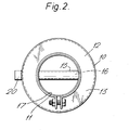
- outer and inner peripherally-interspaced tubular members of a water heater to be interposed in a flue above a boiler and of annular shape in horizontal cross- section when in its upright installed attitude are denoted 10 and 11 respectively.
- the inner member 11 projects at both ends beyond the outer member and is dimensioned for fitment between and integration with spaced and mutually-adjacent ends of axially-aligned flue sections.
- Walls 13 and 14 bridge directly between the ends of the outer member and the periphery of the inner member and sealed to both to define a peripherally continuous watertight chamber or jacket 12 between the two members 10 and 11.
- Outlet and inlet nozzles 20 are provided at or adjacent to opposite ends of the outer member 10 for integration of the chamber 12 into a water circulation system.
- the tubes 14 are fitted in openings in sealed relation with the peripheries thereof.
- the cavities 16 in the tubes 15 and the chamber 12 allows water to be heated to be circulated therethrough.
- the water heater is installed in an upright attitude in a flue immediately above a boiler 19 and in a flue section 19A and a clampable collar 17 is provided for securing the extension above the top wall 13 in a flue section 18 and the nozzles-20 are connected up to a water circulation system for integration of the chamber and cavities therewith. Water circulates through the cavities and chamber and is heated as exhaust gases from combustion of a fire in the boiler 19 pass up through the flue for escape up the chimney.
- the installed attitude of the water heater depends on the attitude of the flue: if the flue is vertical then the water heater is upright, and if the flue is horizontal then so is the water heater.
- the watertight tubes 15 may lie in parallel planes but be angularly displaced one with each other.
Landscapes
- Engineering & Computer Science (AREA)
- Chemical & Material Sciences (AREA)
- Combustion & Propulsion (AREA)
- Mechanical Engineering (AREA)
- General Engineering & Computer Science (AREA)
- Physics & Mathematics (AREA)
- Thermal Sciences (AREA)
- Instantaneous Water Boilers, Portable Hot-Water Supply Apparatuses, And Control Of Portable Hot-Water Supply Apparatuses (AREA)
- Steam Or Hot-Water Central Heating Systems (AREA)
Applications Claiming Priority (2)
| Application Number | Priority Date | Filing Date | Title |
|---|---|---|---|
| GB8211012 | 1982-04-15 | ||
| GB8211012 | 1982-04-15 |
Publications (2)
| Publication Number | Publication Date |
|---|---|
| EP0092375A2 true EP0092375A2 (fr) | 1983-10-26 |
| EP0092375A3 EP0092375A3 (fr) | 1984-01-11 |
Family
ID=10529723
Family Applications (1)
| Application Number | Title | Priority Date | Filing Date |
|---|---|---|---|
| EP83302091A Withdrawn EP0092375A3 (fr) | 1982-04-15 | 1983-04-14 | Chauffe-eau |
Country Status (1)
| Country | Link |
|---|---|
| EP (1) | EP0092375A3 (fr) |
Cited By (2)
| Publication number | Priority date | Publication date | Assignee | Title |
|---|---|---|---|---|
| GB2158209A (en) * | 1984-05-02 | 1985-11-06 | Jonathan Leslie Greenall | Detachable back boiler |
| GR20150100572A (el) * | 2015-12-31 | 2017-08-31 | Αφοι Σ. Ναουμη Ο.Ε. Με Δ.Τ. Heidel | Εναλλακτης θερμοτητας καμιναδας |
Family Cites Families (7)
| Publication number | Priority date | Publication date | Assignee | Title |
|---|---|---|---|---|
| CH87511A (de) * | 1917-12-29 | 1920-12-16 | Kozlowsky Ernst | Warmwasserheizung für kleinere Räume. |
| FR871265A (fr) * | 1941-04-02 | 1942-04-17 | Chauffe-eau | |
| FR1030012A (fr) * | 1950-12-22 | 1953-06-09 | Metallurg Heraud Freres Soc | Appareil chauffe-eau pour fourneaux de cuisine |
| DE2530219A1 (de) * | 1975-07-07 | 1977-02-03 | Kurt Tonk | Lydrodynamischer thermokouvektor |
| DE2814155A1 (de) * | 1978-04-01 | 1979-10-11 | Mth Apparatebau Meissner Gmbh | Waermetauscher fuer verbrennungsanlagen |
| DE2817451A1 (de) * | 1978-04-21 | 1979-10-25 | Juergen Sempf | Schornsteineinsatz zur vermeidung der versottung und zur warmwasserbereitung |
| DE2940718A1 (de) * | 1979-10-08 | 1981-04-16 | Herbert 4408 Dülmen Rottmann | Kaminheizkessel |
-
1983
- 1983-04-14 EP EP83302091A patent/EP0092375A3/fr not_active Withdrawn
Cited By (2)
| Publication number | Priority date | Publication date | Assignee | Title |
|---|---|---|---|---|
| GB2158209A (en) * | 1984-05-02 | 1985-11-06 | Jonathan Leslie Greenall | Detachable back boiler |
| GR20150100572A (el) * | 2015-12-31 | 2017-08-31 | Αφοι Σ. Ναουμη Ο.Ε. Με Δ.Τ. Heidel | Εναλλακτης θερμοτητας καμιναδας |
Also Published As
| Publication number | Publication date |
|---|---|
| EP0092375A3 (fr) | 1984-01-11 |
Similar Documents
| Publication | Publication Date | Title |
|---|---|---|
| ES8406692A1 (es) | Una disposicion de caldera totalamente soldada de un solo calderin para un horno. | |
| ATE70348T1 (de) | Wassererhitzer mit senkrechten rohren. | |
| SU1588289A3 (ru) | Реактор с циркулирующим псевдоожиженным слоем | |
| GB2025599A (en) | Waste-heat recovery method and apparatus | |
| RU93042762A (ru) | Водогрейный котел | |
| EP0205993A3 (fr) | Chauffe-eau chauffé par combustibles solides ayant une marche de flamme inversée pour une installation de chauffage central et en général pour une installation d'eau chaude | |
| JPS55152339A (en) | Liquid heater | |
| GB2183804A (en) | Boilers and water heaters for flues | |
| US4176709A (en) | Stack-type heat exchanger | |
| RU97100098A (ru) | Водогрейный котел | |
| JPS5752715A (en) | Combustion furnace | |
| FR2592137B1 (fr) | Procede d'enrichissement en vapeur d'eau de l'air de combustion fourni a un generateur de chaleur et chaudiere comportant application de ce procede. | |
| EP0092375A3 (fr) | Chauffe-eau | |
| RU2117879C1 (ru) | Отопительный котел | |
| SU909475A1 (ru) | Котел | |
| RU2021561C1 (ru) | Дымовая труба | |
| KR900006507Y1 (ko) | 폐기물소각로를 이용한 보일러 가열장치 | |
| ATE191272T1 (de) | Wärmetauscher | |
| SU1709925A3 (ru) | Котел посто нного сгорани | |
| SU885710A1 (ru) | Многофакельна горелка | |
| KR810000160Y1 (ko) | 급탕용 온수 보일러 | |
| SE8603907D0 (sv) | Vermepanna med forbettrad vermeoverforing | |
| SU985563A2 (ru) | Топочный экран | |
| SU1070402A1 (ru) | Теплогенератор | |
| KR810002319Y1 (ko) | 방사상 흡인통을 입설한 보일러 |
Legal Events
| Date | Code | Title | Description |
|---|---|---|---|
| PUAI | Public reference made under article 153(3) epc to a published international application that has entered the european phase |
Free format text: ORIGINAL CODE: 0009012 |
|
| AK | Designated contracting states |
Designated state(s): AT BE CH DE FR GB IT LI LU NL SE |
|
| PUAL | Search report despatched |
Free format text: ORIGINAL CODE: 0009013 |
|
| AK | Designated contracting states |
Designated state(s): AT BE CH DE FR GB IT LI LU NL SE |
|
| 17P | Request for examination filed |
Effective date: 19840711 |
|
| STAA | Information on the status of an ep patent application or granted ep patent |
Free format text: STATUS: THE APPLICATION IS DEEMED TO BE WITHDRAWN |
|
| 18D | Application deemed to be withdrawn |
Effective date: 19850526 |
|
| RIN1 | Information on inventor provided before grant (corrected) |
Inventor name: MULHOLLAND, WILLIAM JAMES |