EP0092426B1 - Anpassbare Gasturbinenbeschleunigungssteuerung - Google Patents
Anpassbare Gasturbinenbeschleunigungssteuerung Download PDFInfo
- Publication number
- EP0092426B1 EP0092426B1 EP83302209A EP83302209A EP0092426B1 EP 0092426 B1 EP0092426 B1 EP 0092426B1 EP 83302209 A EP83302209 A EP 83302209A EP 83302209 A EP83302209 A EP 83302209A EP 0092426 B1 EP0092426 B1 EP 0092426B1
- Authority
- EP
- European Patent Office
- Prior art keywords
- acceleration
- engine
- schedule
- rate
- discharge pressure
- Prior art date
- Legal status (The legal status is an assumption and is not a legal conclusion. Google has not performed a legal analysis and makes no representation as to the accuracy of the status listed.)
- Expired
Links
- 230000001133 acceleration Effects 0.000 title claims description 68
- 230000003044 adaptive effect Effects 0.000 title description 5
- 239000000446 fuel Substances 0.000 claims description 42
- 239000003607 modifier Substances 0.000 claims description 29
- 230000008859 change Effects 0.000 claims description 13
- 238000000034 method Methods 0.000 claims description 10
- 238000010586 diagram Methods 0.000 description 6
- 230000004048 modification Effects 0.000 description 3
- 238000012986 modification Methods 0.000 description 3
- 230000004044 response Effects 0.000 description 3
- 230000006870 function Effects 0.000 description 2
- 230000009471 action Effects 0.000 description 1
- 230000007812 deficiency Effects 0.000 description 1
- 238000001514 detection method Methods 0.000 description 1
- 230000006866 deterioration Effects 0.000 description 1
- 230000004069 differentiation Effects 0.000 description 1
- 238000005070 sampling Methods 0.000 description 1
Images




Classifications
-
- F—MECHANICAL ENGINEERING; LIGHTING; HEATING; WEAPONS; BLASTING
- F02—COMBUSTION ENGINES; HOT-GAS OR COMBUSTION-PRODUCT ENGINE PLANTS
- F02C—GAS-TURBINE PLANTS; AIR INTAKES FOR JET-PROPULSION PLANTS; CONTROLLING FUEL SUPPLY IN AIR-BREATHING JET-PROPULSION PLANTS
- F02C9/00—Controlling gas-turbine plants; Controlling fuel supply in air- breathing jet-propulsion plants
- F02C9/26—Control of fuel supply
- F02C9/28—Regulating systems responsive to plant or ambient parameters, e.g. temperature, pressure, rotor speed
-
- F—MECHANICAL ENGINEERING; LIGHTING; HEATING; WEAPONS; BLASTING
- F05—INDEXING SCHEMES RELATING TO ENGINES OR PUMPS IN VARIOUS SUBCLASSES OF CLASSES F01-F04
- F05D—INDEXING SCHEME FOR ASPECTS RELATING TO NON-POSITIVE-DISPLACEMENT MACHINES OR ENGINES, GAS-TURBINES OR JET-PROPULSION PLANTS
- F05D2270/00—Control
- F05D2270/01—Purpose of the control system
- F05D2270/04—Purpose of the control system to control acceleration (u)
-
- F—MECHANICAL ENGINEERING; LIGHTING; HEATING; WEAPONS; BLASTING
- F05—INDEXING SCHEMES RELATING TO ENGINES OR PUMPS IN VARIOUS SUBCLASSES OF CLASSES F01-F04
- F05D—INDEXING SCHEME FOR ASPECTS RELATING TO NON-POSITIVE-DISPLACEMENT MACHINES OR ENGINES, GAS-TURBINES OR JET-PROPULSION PLANTS
- F05D2270/00—Control
- F05D2270/01—Purpose of the control system
- F05D2270/10—Purpose of the control system to cope with, or avoid, compressor flow instabilities
- F05D2270/101—Compressor surge or stall
Definitions
- the present invention relates to the exercise of control over the delivery of fuel to a gas turbine engine.
- surge is a mismatch between the speed of the compressor blades and the incoming air.
- Gas turbine engine surges are characterized by a sudden and large loss of power, a loss of air flow, an increase in temperature and mechanical vibration. These mechanical vibrations, as well as the temperature increases, impose substantial stress on the engine and particularly on the turbine blades. While also occurring under other operating conditions, engine surge will most often occur during acceleration.
- Prior attempts to ensure that engine surge will not occur have concentrated on the establishment of fuel flow rate schedules.
- prior art fuel controls will be pre-programmed with an acceleration schedule and, in theory, if fuel flow is maintained in accordance with the requirements of the schedule, the engine is accelerated without surge. It is to be noted that, if an excess of fuel is delivered to the engine during surge, the engine is likely to stay in the surge condition or experience multiple surges.
- the prior art controls will typically include a safety factor which is known as the surge margin.
- the surge margin will be taken into account in deriving the acceleration schedule and the engine will be capable of accepting a predetermined percentage of additional fuel flow before surge will occur.
- Prior art closed loop acceleration controls essentially constitute a plot of the ratio of the rate of change of gas generator speed to compressor inlet pressure versus corrected gas generator speed. This type of control is known in the art as an NDOT/PT2 control. If the engine surges, an NDOT/PT2 control will in itself increase fuel flow to compensate for the stalled acceleration. This increase in fuel flow, in turn, increases the probability that the engine will not accelerate through the surge prone area, i.e., multiple surges will result, and corrective action by the pilot will be required.
- Both United States Patent No. 3971208 and European Patent Application No. 0025406 disclose a method of controlling the delivery of fuel to a gas turbine engine during acceleration of the engine, the engine including a gas generator having a compressor, said method including storing data comprising an acceleration schedule.
- the U.S. Patent shows a surge valve logic system, including a surge schedule, which prevents excessive bleed and loss of engine efficiency. Valve area is continually adjusted as engine speed changes.
- the surge schedule - which is corrected ratio units to corrected speed - is adjusted in accordance with valve opening. The difference between the system output ratio units and scheduled ratio units is determinative of valve.position.
- the system disclosed in this patent is not an adaptive system.
- the European application discloses a system in which the acceleration schedule is an NDOT acceleration schedule, (NDOT/ambient pressure versus speed), but again the system has no adaptive features.
- a method of controlling the delivery of fuel to a gas turbine engine during acceleration of the engine including a gas generator having a compressor and further including a fuel metering system which is responsive to fuel flow command signals for varying the rate of delivery of fuel to the engine, which method includes providing an engine acceleration schedule and which is characterized by:
- the present invention overcomes the above- discussed and other deficiencies of the prior art by providing for active modification of the acceleration schedule of a gas turbine engine fuel control.
- the region of the acceleration schedule where the surge was encountered will be lowered to increase surge margin.
- Apparatus for controlling the delivery of fuel to a gas turbine engine during acceleration of the engine preferably senses the decay rate of engine compressor discharge pressure during surge and modifies the pre-programmed acceleration schedule so as to increase surge margin.
- an adaptive acceleration schedule is provided wherein "modifiers" are stored which correspond to each of the stored acceleration schedule break- points.
- the modifiers are scale factors which are normally equal to unity. However, each time a surge is detected, the modifier which corresponds to the point on the acceleration schedule where the surge was experienced will be decremented by a preselected percentage.
- the fuel flow related information from the acceleration schedule is multiplied by the modifier with the result that, subsequent to a surge having been detected, future accelerations will be modified within a small corrected speed band surrounding the surge point.
- a closed loop electronic fuel control is depicted in the form of a functional block diagram.
- the fuel control adjusts the rate of flow of a combustible fuel to a gas turbine engine, indicated generally at 10, by delivering a fuel flow demand signal WF * to a fuel metering system 12.
- metering system 12 will cause the rate of flow WF of pressurized fuel to engine 10 to be varied in accordance with the operating conditions and, in an aircraft environment, in accordance with the pilot's command.
- Engine 10 will, as is standard practice in the art, be instrumented such that signals commensurate with a plurality of engine operating parameters will be provided. These operating parameter signals will include gas generator speed NG, compressor discharge pressure CDP, power turbine speed NP and gas generator compressor inlet temperature T2.
- the WF * signal delivered to the metering system 12 will be that one of several simultaneously generated fuel flow rate related signals which corresponds to the lowest value of fuel flow.
- a plurality of fuel flow related signals may be provided by speed governors which have been indicated generally at 14.
- speed governors may be prior art electronic governors or they may be governors of the type described in published European application No. 092425, entitled “Gas Turbine Engine Fuel Control” filed on 19th April 1983.
- the fuel flow related signal or signals provided by the governors 14 are delivered to an auc- tioneering circuit or lowest value gate 16.
- a fuel flow related signal from an acceleration gain control 18, which is in part derived from a pre-programmed acceleration schedule is also delivered as an input to gate 16.
- the fuel flow related signal passed by gate 16 is delivered to an altitude compensation circuit 20 wherein it is multiplied by a signal commensurate with the actual instantaneous compressor discharge pressure (CDP) which, presuming that the engine is not in surge, is related to altitude.
- CDP instantaneous compressor discharge pressure
- the output of compensation circuit 20 is the WF * command signal for the metering system 12.
- the gas generator compressor discharge pressure signal provided by the engine sensor is also delivered as the input to a surge detector which has been indicated generally at 22.
- surge detector 22 the CDP signal is differentiated, in a differentiator 24, to provide a CDP signal the magnitude of which is a measure of the rate of change of gas generator compressor discharge pressure.
- the output of differentiator 24 and a surge limit signal i.e., a constant commensurate with a value of CDP which corresponds to an engine'surge, are compared in a comparator 26.
- the magnitude of the constant delivered to comparator 26 will be such that the comparator will provide a first input to an AND gate 28 when the rate of change of the compressor discharge pressure is greater than the predetermined surge limit level, i.e., gate 28 will be enabled when the engine is in surge.
- the second input to gate 28 will be a signal provided by gate 16 which is indicative of the passage, to compensation circuit 20, of the acceleration limit signal provided by gain control circuit 18.
- "AND" gate 28 will provide a reset signal to a scale factor modifier, indicated generally at 30, when the engine is in the acceleration mode and a surge occurs.
- the fuel control will vary the rate of delivery of fuel to the engine as required by an acceleration schedule.
- This acceleration schedule will have been provided by the manufacturer, will pertain to the engine in its new and thus presumably rated condition and will be stored in the suitable memory or look-up table 32.
- the acceleration schedule comprises a plot of the ratio of rate of change of gas generator speed to compressor discharge pressure (NDOT/CDP) versus the ratio of gas generator speed to inlet temperature correction (NG/V6) which quantity is commonly termed corrected speed.
- NDOT/CDP rate of change of gas generator speed to compressor discharge pressure
- NG/V6 gas generator speed to inlet temperature correction
- the ratio NG/V8 or corrected speed addresses memory 32 so as to read out an NDOT/ CDP value for each value of the NG/V8 ratio.
- the value read out of memory 32 is applied to a multiplier 36 wherein it is multiplied by an output signal provided by modifier 30 as will be described in greater detail below. Suffice it for the present to note that the output of multiplier 36 will be a (K M ) (NDOT/CDP) signal, i.e., a value derived from the stored acceleration schedule as modified by the scale factor K M .
- the modified NDOT/CDP signal is multiplied, in a further multiplier 38, by a signal commensurate with the actual sensed value of CDP to provide an NDOT signal which is integrated, in integrator 40, to provide a gas generator speed signal as determined by the modified value taken from the acceleration schedule.
- the NG signal provided by integrator 40 is algebraically summed, in a summation circuit 42, with the actual instantaneous NG to provide an NG error signal.
- the NG error signal is delivered to the acceleration gain control circuit 18 wherein a fixed gain of fuel flow per compressor discharge pressure is computed as a function of the speed error.
- the control mode of the present invention may be implemented in the form of a suitably programmed microprocessor which functions in accordance with the flow diagram of FIGURES 1-3.
- the gas generator speed NG is sensed to determine whether the speed is below 60% of maximum. The purpose of this test is to eliminate the possibility of effecting a modification of the acceleration schedule as a result of engine parameters sensed during start-up. If the speed is not less than 60% of maximum, as indicated at 52, a determination is made as to whether the engine is in fact in the acceleration mode. If the engine is in the acceleration mode a surge detection subroutine 54, which is represented in FIGURE 2, is implemented.
- This routine calls for a compressor discharge pressure timing counter to be incremented as indicated at 56.
- the state of the counter is then sensed, as indicated at 58 and, if the count is at zero, the CDP counter is reset to -2 in step 60.
- the present input sampling of CDP is compared to the value of CDP that was input when the counter was last at zero. This represents values of CDP at the beginning and end of a fixed time increment used for differentiation.
- the difference between the present and last CDP represents CDP, which is compared with the surge limit in step 64.
- CDP is greater than the surge limit, indicating that a surge has occurred, there will be a return to the surge compensating routine, as indicated at 66, in order to find the modifier address as indicated at 68 in FIGURE 1.
- the last value of compressor discharge pressure will, as indicated at 70, be reset to the present value of CDP for recomputing CDP.
- the surge detector subroutine is then exited back to the main program. If the count resulting from the incrementing of the CDP counter in step 56 does not result in zero, indicating that the differentiating time has not expired, the subroutine will also be exited back to the main program.
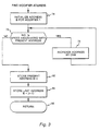
- the modifier address will be found in the manner indicated in FIGURE 3.
- the modifier address is initialized to the lowest corrected speed setting.
- the acceleration schedule addresses A -- A + n -- A + m are the addresses in memory 32 where the NDOT/CDP acceleration values, respectively NDOT/CDP(o) --- NDOT/ CDP(n) --- NDOT/CDP(m) are stored. These acceleration values correspond to respective engine speed points NG(o) --- NG(n) --- NG(m).
- the modifier addresses which correspond to the addresses of memory 32 are identified by the operator B and the modifier values stored at these addresses are represented in the last column of the look-up table of FIGURE 4. As indicated above, initially the stored modifier values will all be equal to one (1).
- the equations on FIGURE 4 show how the acceleration schedule is interpolated between two look-up table points and how the modifier scale factor is interpolated from two look-up table points.
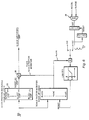
- FIGURE 6 is a functional block diagram of the scale factor modifier of FIGURE 5.
- the present invention is applicable to either open or closed loop controls.
- the invention provides for the modification of a pre-programmed acceleration control schedule as a result of engine surges. More specifically, this invention is directed to an adaptive gas turbine engine acceleration control wherein, in response to engine surges, a programmed acceleration schedule is modified on-line to avoid future surges when the same operating conditions are encountered.
Landscapes
- Engineering & Computer Science (AREA)
- Chemical & Material Sciences (AREA)
- Combustion & Propulsion (AREA)
- Mechanical Engineering (AREA)
- General Engineering & Computer Science (AREA)
- Control Of Positive-Displacement Air Blowers (AREA)
Claims (4)
Applications Claiming Priority (2)
| Application Number | Priority Date | Filing Date | Title |
|---|---|---|---|
| US369531 | 1982-04-19 | ||
| US06/369,531 US4490791A (en) | 1982-04-19 | 1982-04-19 | Adaptive gas turbine acceleration control |
Publications (2)
| Publication Number | Publication Date |
|---|---|
| EP0092426A1 EP0092426A1 (de) | 1983-10-26 |
| EP0092426B1 true EP0092426B1 (de) | 1988-01-07 |
Family
ID=23455853
Family Applications (1)
| Application Number | Title | Priority Date | Filing Date |
|---|---|---|---|
| EP83302209A Expired EP0092426B1 (de) | 1982-04-19 | 1983-04-19 | Anpassbare Gasturbinenbeschleunigungssteuerung |
Country Status (4)
| Country | Link |
|---|---|
| US (1) | US4490791A (de) |
| EP (1) | EP0092426B1 (de) |
| CA (1) | CA1201188A (de) |
| DE (1) | DE3375181D1 (de) |
Cited By (1)
| Publication number | Priority date | Publication date | Assignee | Title |
|---|---|---|---|---|
| US8555653B2 (en) | 2009-12-23 | 2013-10-15 | General Electric Company | Method for starting a turbomachine |
Families Citing this family (24)
| Publication number | Priority date | Publication date | Assignee | Title |
|---|---|---|---|---|
| US4608833A (en) * | 1984-12-24 | 1986-09-02 | Borg-Warner Corporation | Self-optimizing, capacity control system for inverter-driven centrifugal compressor based water chillers |
| GB2228977B (en) * | 1985-08-02 | 1990-11-21 | Lucas Ind Plc | Running control for a gas turbine engine |
| DE3830804A1 (de) * | 1988-09-09 | 1990-03-15 | Mtu Muenchen Gmbh | Verfahren und anordnung zur regelung der brennstoffzufuhr einer gasturbine |
| GB8911806D0 (en) * | 1989-05-23 | 1989-07-12 | Rolls Royce Plc | Gas turbine engine fuel control system with enhanced relight capability |
| US5126933A (en) * | 1990-02-07 | 1992-06-30 | White Iii Charles A | Self-learning memory unit for process controller and self-updating function generator |
| US5040119A (en) * | 1990-04-05 | 1991-08-13 | Caterpillar Inc. | Draft control apparatus and method |
| US5285634A (en) * | 1991-12-09 | 1994-02-15 | United Technologies Corporation | Aircraft gas turbine engine control |
| US5732546A (en) * | 1996-07-19 | 1998-03-31 | General Electric Company | Transient turbine overtemperature control |
| US5694760A (en) * | 1996-07-19 | 1997-12-09 | General Electric Company | Cumbustor lean flameout control |
| US7376504B2 (en) * | 2001-11-15 | 2008-05-20 | Goodrich Pump & Engine Control Systems, Inc. | Method of engine surge discrimination |
| US6820429B2 (en) | 2001-11-15 | 2004-11-23 | Goodrich Pump & Engine Control Systems, Inc. | Adaptive acceleration schedules for gas turbine engine control systems |
| US6823675B2 (en) * | 2002-11-13 | 2004-11-30 | General Electric Company | Adaptive model-based control systems and methods for controlling a gas turbine |
| US7712299B2 (en) * | 2006-09-05 | 2010-05-11 | Conocophillips Company | Anti-bogdown control system for turbine/compressor systems |
| US9145833B2 (en) | 2010-05-25 | 2015-09-29 | General Electric Company | Gas turbine startup control |
| US8899488B2 (en) | 2011-05-31 | 2014-12-02 | United Technologies Corporation | RFID tag system |
| FR2977638B1 (fr) * | 2011-07-04 | 2017-10-06 | Snecma | Procede de commande pour transitoires de regime d'une turbomachine |
| US10094292B2 (en) * | 2012-03-02 | 2018-10-09 | Hamilton Sundstrand Corporation | Method of acceleration control during APU starting |
| US8720258B2 (en) * | 2012-09-28 | 2014-05-13 | United Technologies Corporation | Model based engine inlet condition estimation |
| CN106323640B (zh) * | 2015-06-30 | 2018-10-30 | 中航空天发动机研究院有限公司 | 一种航空发动机加减速供油试验方法 |
| FR3089263B1 (fr) * | 2018-12-03 | 2020-12-11 | Safran Aircraft Engines | Procédé et dispositif de détection d’un décollement tournant affectant un compresseur d’un turboréacteur |
| US11643981B2 (en) * | 2021-08-30 | 2023-05-09 | Pratt & Whitney Canada Corp. | System and method for controlling fuel flow to an aircraft engine during start |
| CN114837821B (zh) * | 2022-04-29 | 2023-07-07 | 中国航发沈阳发动机研究所 | 一种航空发动机地面起动供油规律自适应调整方法及系统 |
| CN115638054B (zh) * | 2022-08-26 | 2025-09-30 | 中国航发沈阳发动机研究所 | 一种航空发动机转速上升率控制规律的设计方法 |
| CN118686701B (zh) * | 2024-08-27 | 2024-11-29 | 中国航发湖南动力机械研究所 | 发动机加减速防喘控制方法、装置、电子设备及存储介质 |
Citations (2)
| Publication number | Priority date | Publication date | Assignee | Title |
|---|---|---|---|---|
| US3971208A (en) * | 1974-04-01 | 1976-07-27 | The Garrett Corporation | Gas turbine fuel control |
| EP0025406A1 (de) * | 1979-08-23 | 1981-03-18 | United Technologies Corporation | System und Verfahren zur elektronischen Brennstoffregelung |
Family Cites Families (7)
| Publication number | Priority date | Publication date | Assignee | Title |
|---|---|---|---|---|
| US2974483A (en) * | 1956-09-28 | 1961-03-14 | John C Sanders | Acceleration control for gas turbine engines with compressor surge limiting |
| US3482396A (en) * | 1967-08-17 | 1969-12-09 | Gen Motors Corp | Electronic fuel control system |
| US4117668A (en) * | 1975-11-19 | 1978-10-03 | United Technologies Corporation | Stall detector for gas turbine engine |
| US4249238A (en) * | 1978-05-24 | 1981-02-03 | The United States Of America As Represented By The Administrator Of The National Aeronautics And Space Administration | Apparatus for sensor failure detection and correction in a gas turbine engine control system |
| US4407013A (en) * | 1980-10-20 | 1983-09-27 | Leeds & Northrup Company | Self tuning of P-I-D controller by conversion of discrete time model identification parameters |
| US4432201A (en) * | 1981-01-14 | 1984-02-21 | Aviation Electric Ltd. | Acceleration limit reset |
| US4449360A (en) * | 1981-04-30 | 1984-05-22 | Aviation Electric Ltd. | Stall detector and surge prevention feature for a gas turbine engine |
-
1982
- 1982-04-19 US US06/369,531 patent/US4490791A/en not_active Expired - Lifetime
-
1983
- 1983-04-18 CA CA000426110A patent/CA1201188A/en not_active Expired
- 1983-04-19 EP EP83302209A patent/EP0092426B1/de not_active Expired
- 1983-04-19 DE DE8383302209T patent/DE3375181D1/de not_active Expired
Patent Citations (2)
| Publication number | Priority date | Publication date | Assignee | Title |
|---|---|---|---|---|
| US3971208A (en) * | 1974-04-01 | 1976-07-27 | The Garrett Corporation | Gas turbine fuel control |
| EP0025406A1 (de) * | 1979-08-23 | 1981-03-18 | United Technologies Corporation | System und Verfahren zur elektronischen Brennstoffregelung |
Cited By (1)
| Publication number | Priority date | Publication date | Assignee | Title |
|---|---|---|---|---|
| US8555653B2 (en) | 2009-12-23 | 2013-10-15 | General Electric Company | Method for starting a turbomachine |
Also Published As
| Publication number | Publication date |
|---|---|
| CA1201188A (en) | 1986-02-25 |
| DE3375181D1 (en) | 1988-02-11 |
| US4490791A (en) | 1984-12-25 |
| EP0092426A1 (de) | 1983-10-26 |
Similar Documents
| Publication | Publication Date | Title |
|---|---|---|
| US4490791A (en) | Adaptive gas turbine acceleration control | |
| EP0092425B1 (de) | Brennstoffregler für Gasturbinentriebwerke | |
| US4622808A (en) | Surge/stall cessation detection system | |
| EP1444428B1 (de) | Verfahren und vorrichtung zur vermeidung des pumpens in einer gasturbine | |
| US5272637A (en) | Method and apparatus for controlling the supply of fuel to a gas turbine during load rejection | |
| US5083277A (en) | Fuel control system | |
| US5051918A (en) | Gas turbine stall/surge identification and recovery | |
| EP0661426B1 (de) | Gasturbinenanlage und Verfahren zu deren Betrieb | |
| CA1096463A (en) | Control for gas turbine engine | |
| US4275557A (en) | Method and apparatus for controlling thrust in a gas turbine engine | |
| EP0187114B1 (de) | Transiente Abblasregelung für einen Gasturbinenmotor | |
| US5023793A (en) | Apparatus and method for dynamic compensation of a propeller pitch speed control governor | |
| US4998949A (en) | Overspeed limiter for gas turbine aeroengine | |
| CA1240380A (en) | Transient derivative scheduling control system | |
| EP3351771B1 (de) | Gasturbinenmotorbrennstoffsteuerungssystem und -verfahren | |
| US3994623A (en) | Method and apparatus for controlling a dynamic compressor | |
| US4087961A (en) | Fuel control system for gas turbine engine operated on gaseous fuel | |
| EP0376875B1 (de) | Rauschempfindliche signalabhängige Schaltung | |
| US20040187473A1 (en) | Acceleration control in multi spool gas turbine engine | |
| US3979655A (en) | Control system for controlling a dynamic compressor | |
| GB2160999A (en) | Modification of regulation values in anticipation of compensatory change in the values | |
| US4532763A (en) | Isochronous gas turbine speed control | |
| US3882672A (en) | System arrangement for governing gas turbine engines, especially gas turbine aero-engines | |
| EP0063999A1 (de) | Brennstoffregeleinrichtung für eine Gasturbine | |
| US4672806A (en) | Isochronous gas turbine speed control |
Legal Events
| Date | Code | Title | Description |
|---|---|---|---|
| PUAI | Public reference made under article 153(3) epc to a published international application that has entered the european phase |
Free format text: ORIGINAL CODE: 0009012 |
|
| AK | Designated contracting states |
Designated state(s): DE FR GB IT |
|
| 17P | Request for examination filed |
Effective date: 19840327 |
|
| GRAA | (expected) grant |
Free format text: ORIGINAL CODE: 0009210 |
|
| AK | Designated contracting states |
Kind code of ref document: B1 Designated state(s): DE FR GB IT |
|
| REF | Corresponds to: |
Ref document number: 3375181 Country of ref document: DE Date of ref document: 19880211 |
|
| RAP2 | Party data changed (patent owner data changed or rights of a patent transferred) |
Owner name: COLT INDUSTRIES INC. |
|
| ITF | It: translation for a ep patent filed | ||
| RAP2 | Party data changed (patent owner data changed or rights of a patent transferred) |
Owner name: COLT INDUSTRIES INC |
|
| RAP4 | Party data changed (patent owner data changed or rights of a patent transferred) |
Owner name: COLT INDUSTRIES INC |
|
| ET | Fr: translation filed | ||
| REG | Reference to a national code |
Ref country code: GB Ref legal event code: 732 |
|
| REG | Reference to a national code |
Ref country code: FR Ref legal event code: TP |
|
| PLBE | No opposition filed within time limit |
Free format text: ORIGINAL CODE: 0009261 |
|
| STAA | Information on the status of an ep patent application or granted ep patent |
Free format text: STATUS: NO OPPOSITION FILED WITHIN TIME LIMIT |
|
| ITPR | It: changes in ownership of a european patent |
Owner name: FUSIONI;COLT INDUSTRIES OPERATING CORP. |
|
| 26N | No opposition filed | ||
| ITTA | It: last paid annual fee | ||
| REG | Reference to a national code |
Ref country code: GB Ref legal event code: IF02 |
|
| PGFP | Annual fee paid to national office [announced via postgrant information from national office to epo] |
Ref country code: FR Payment date: 20020401 Year of fee payment: 20 |
|
| PGFP | Annual fee paid to national office [announced via postgrant information from national office to epo] |
Ref country code: GB Payment date: 20020416 Year of fee payment: 20 |
|
| PGFP | Annual fee paid to national office [announced via postgrant information from national office to epo] |
Ref country code: DE Payment date: 20020418 Year of fee payment: 20 |
|
| PG25 | Lapsed in a contracting state [announced via postgrant information from national office to epo] |
Ref country code: GB Free format text: LAPSE BECAUSE OF EXPIRATION OF PROTECTION Effective date: 20030418 |
|
| REG | Reference to a national code |
Ref country code: GB Ref legal event code: PE20 |