EP0092484A1 - Anzeigevorrichtung für Kraftfahrzeugdrehzahlmesser - Google Patents
Anzeigevorrichtung für Kraftfahrzeugdrehzahlmesser Download PDFInfo
- Publication number
- EP0092484A1 EP0092484A1 EP83400770A EP83400770A EP0092484A1 EP 0092484 A1 EP0092484 A1 EP 0092484A1 EP 83400770 A EP83400770 A EP 83400770A EP 83400770 A EP83400770 A EP 83400770A EP 0092484 A1 EP0092484 A1 EP 0092484A1
- Authority
- EP
- European Patent Office
- Prior art keywords
- revolutions
- engine
- warning
- driving
- display device
- Prior art date
- Legal status (The legal status is an assumption and is not a legal conclusion. Google has not performed a legal analysis and makes no representation as to the accuracy of the status listed.)
- Granted
Links
Images

Classifications
-
- G—PHYSICS
- G01—MEASURING; TESTING
- G01P—MEASURING LINEAR OR ANGULAR SPEED, ACCELERATION, DECELERATION, OR SHOCK; INDICATING PRESENCE, ABSENCE, OR DIRECTION, OF MOVEMENT
- G01P1/00—Details of instruments
- G01P1/07—Indicating devices, e.g. for remote indication
- G01P1/08—Arrangements of scales, pointers, lamps or acoustic indicators, e.g. in automobile speedometers
- G01P1/10—Arrangements of scales, pointers, lamps or acoustic indicators, e.g. in automobile speedometers for indicating predetermined speeds
-
- G—PHYSICS
- G01—MEASURING; TESTING
- G01P—MEASURING LINEAR OR ANGULAR SPEED, ACCELERATION, DECELERATION, OR SHOCK; INDICATING PRESENCE, ABSENCE, OR DIRECTION, OF MOVEMENT
- G01P1/00—Details of instruments
- G01P1/07—Indicating devices, e.g. for remote indication
- G01P1/08—Arrangements of scales, pointers, lamps or acoustic indicators, e.g. in automobile speedometers
- G01P1/10—Arrangements of scales, pointers, lamps or acoustic indicators, e.g. in automobile speedometers for indicating predetermined speeds
- G01P1/103—Arrangements of scales, pointers, lamps or acoustic indicators, e.g. in automobile speedometers for indicating predetermined speeds by comparing the value of the measured signal with one or several reference values
-
- G—PHYSICS
- G01—MEASURING; TESTING
- G01R—MEASURING ELECTRIC VARIABLES; MEASURING MAGNETIC VARIABLES
- G01R13/00—Arrangements for displaying electric variables or waveforms
- G01R13/40—Arrangements for displaying electric variables or waveforms using modulation of a light beam otherwise than by mechanical displacement, e.g. by Kerr effect
- G01R13/404—Arrangements for displaying electric variables or waveforms using modulation of a light beam otherwise than by mechanical displacement, e.g. by Kerr effect for discontinuous display, i.e. display of discrete values
- G01R13/405—Arrangements for displaying electric variables or waveforms using modulation of a light beam otherwise than by mechanical displacement, e.g. by Kerr effect for discontinuous display, i.e. display of discrete values using a plurality of active, i.e. light emitting, e.g. electro-luminescent elements, i.e. bar graphs
- G01R13/406—Arrangements for displaying electric variables or waveforms using modulation of a light beam otherwise than by mechanical displacement, e.g. by Kerr effect for discontinuous display, i.e. display of discrete values using a plurality of active, i.e. light emitting, e.g. electro-luminescent elements, i.e. bar graphs representing measured value by a dot or a single line
Definitions
- This invention relates to a display unit of tachometer for automobile, in which liquid-crystal bar graphic displaying is used.
- one of the objects of this invention is to provide a display unit of tachometer for automobile equipped with the technical means capable of displaying both actual number of revolutions ans preset number of revolutions of automobile engine at an inexpensive cost and in a manner of watching these revolutions readily on one and the same display device.
- Another object of this invention is to provide a novel display unit of tachometer for automobile capable of fulfilling various display functions with bar graphic displaying under the display formation by plane liquid crystal, displaying clearly high speed warning revolution area or high speed critical revolution area shown by yellow zone or red zone and giving simultaneously alarming effects by means of flickering and the like.
- this invention relates to a display unit of tachometer for automobile, displaying necessary number of revolutions of engine with scales at the basic scale units of each segment on a display device of bar graphic displaying provided with necessary number of segments, displaying constantly warning number of revolutions of engine by selectively driving only the segment displaying desired warning number of revolutions, displaying actual number of revolutions of engine by driving all the segments corresponding to number of revolutions other than the actual number of revolutions, or displaying number of revolutions exceeding the warning number of revolutions by stopping the driving of only the segment corresponding to the warning number of revolutions when the number of revolutions of engine exceed the warning number of revolutions and further displaying critical number of revolutions with the flickering of the display device by driving intermittently each segment when number of revolutions of engine reach preset critical number of revolutions.
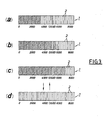
- oblique line portion shows working state
- line-less portion shows inactive state
- Numeral 1 is a display device which is formed as the bar graphic displaying A cimprising necessary number of segments 2 using, for example, liquid crystal. Namely, in the illustration, n-piece segments 2 same in size of long and narrow plates are arranged and connected together, and each one piece of segments are displayed in sequence as one scale of basic units, for examples 100 rpm, 200 rpm and so on.
- Numeral 3 is scales shown on the necessary positions of the aforesaid display device 1. And, in case of necessity, color displays may be made, together with the scales 3, with yellow for warning revolution area, red for critical revolution area, and so on.
- the display device 1 can display proper numerical values as a result of changes in condition of light and darkness, transparency and turbidity, etc. which are caused by the changes of optical properties of the liquid crystal relative to the necessary segment 2 on which voltage is impressed and are different from the liquid crystal relative to other segments on which no voltage is impressed.
- the display device 1 may take the necessary construction easy to watch for a driver in the daytime and nighttime with transmitted light, reflected light, etc. by display means under DS (dynamic scattering) system, TN (twisted nematic) system, ECB (electrically controlled birefringence) system, PC (phase change) system, etc. according to the difference in the mechanism transforming the changes in condition of liquid crystal caused by electric signals into optical information.
- DS dynamic scattering
- TN twisted nematic
- ECB electrically controlled birefringence
- PC phase change
- each segment 2 can freely be arranged, for example the arrangement in up-to-down direction, not to speak of the arrangement in right-to-left direction as shown, and can be constructed to desired shapes without limiting to the construction shown, while a number of display device 1 can be formed to circular arc, circle, circular ring, etc. as desired according to the shapes of segments.
- Numeral 4 is an engine revolution operational circuit which is so arranged as to receive ignition pulse signals of automobile engine and to operate number of revolutions per minute (rpm) of engine as desired.
- Numeral 5 is a warning revolution decision circuit, in which warning number of revolutions are selectively set to 5 500 rpm, and is connected to the operational circuit 4. And further, when number of revolutions per minute of engine are smaller in value than 5 500 rpm to the segment 2 corresponding to 5 500 rpm of the display device 1 through driving circuit 6 of the display device 1, a warning revolution decision circuit 5 is capable of making the display device 1 perform liquid-crystal displaying by means of giving optical changes of liquid crystal of the segment 2 through connecting wire 10 by the driving circuit 6 ; when number of revolutions per minute of engine are larger in value than 5 500 rpm, the warning revolution decision circuit 5 is so arranged as to enable the segment 2 corresponding to 5 500 rpm to stop its driving by stopping the functioning of the driving circuit 6.
- Numeral 7 is a critical revolution decision circuit, in which critical number of revolutions are selectively set to 6 000 rpm, and is connected to the engine revolution operational circuit 4. And further, when number of revolutions per minute of engine reach the value exceeding 6 000 rpm to the segment 2 corresponding to 6 000 rpm of the display device 1 through the driving circuit 6 of the display device 1, the critical revolution decision circuit 7 is capable to making the display device 1 perform flickering display of all the segments 2 corresponding to the number of revolutions per minute responding to higher speed by giving intermittently the display inhibiting signals to the driving circuit 6. And also, it may be so arranged as to readily change the aforesaid warning number of revolutions and critical number of revolutions by means of setting.
- Numeral 8 is a bar graph decoder for making the driving circuit 6 of the display device 1 function, and is so arranged as to drive n- 1 pieces of segment 2 by each connecting wire 9 with the exclusion of 1 piece of segment 2, which is driven by signals transmitted by the aforesaid warning revolution decision circuit 5, from n-piece segments 2 constructing the display device 1.
- the bar graph decoder 8 is not connected with the segments corresponding to said number of revolutions, whereby the segments do not function to come to the state in Fig. 3 (b), and other segments 2 function to bring the liquid-crystal display.
- the warning revolution decision circuit 5 in which warning number of revolutions are set to 5,500 rpm, transmits output signals so as to drive segments 2 corresponding to number of revolutions smaller in value than 5,500 rpm through the driving circuit 6 when number of revolutions of engine are smaller in value than 5,500 rpm, so that the circuit 5 can perform the liquid-crystal display as other oblique line portions of Fig. 3 (a) by driving only the segments 2 corresponding to said number of revolutions.
- This invention has an advantage of making a driver enjoy safe driving by preventing reckless driving because, as mentioned above, of displaying number of revolutions of engine on the display device of bar graphic displaying by using segments such as liquid crystal and of making it possible for a driver to constantly compare number of revolutions of engine with warning number of revolutions by setting such number of revolutions and by making the segments corresponding to such warning number of revolutions, and has further advantage of being able to secure more safety because, as mentioned above, of making the bar graphic displaying of the display device flicker to make it possible to give a driver warning when number of revolutions of engine exceed the critical number of revolutions.
- the display device which is constructed by bar graphic display, has the effects of good style and easy watch for a driver.
Landscapes
- Physics & Mathematics (AREA)
- General Physics & Mathematics (AREA)
- Indicating Measured Values (AREA)
- Instrument Panels (AREA)
Applications Claiming Priority (2)
| Application Number | Priority Date | Filing Date | Title |
|---|---|---|---|
| JP64875/82 | 1982-04-20 | ||
| JP57064875A JPS58190766A (ja) | 1982-04-20 | 1982-04-20 | 自動車用タコメ−タの表示装置 |
Publications (2)
| Publication Number | Publication Date |
|---|---|
| EP0092484A1 true EP0092484A1 (de) | 1983-10-26 |
| EP0092484B1 EP0092484B1 (de) | 1986-10-29 |
Family
ID=13270737
Family Applications (1)
| Application Number | Title | Priority Date | Filing Date |
|---|---|---|---|
| EP19830400770 Expired EP0092484B1 (de) | 1982-04-20 | 1983-04-19 | Anzeigevorrichtung für Kraftfahrzeugdrehzahlmesser |
Country Status (4)
| Country | Link |
|---|---|
| EP (1) | EP0092484B1 (de) |
| JP (1) | JPS58190766A (de) |
| DE (1) | DE3367283D1 (de) |
| ES (1) | ES8404059A1 (de) |
Cited By (3)
| Publication number | Priority date | Publication date | Assignee | Title |
|---|---|---|---|---|
| WO1993002253A1 (de) * | 1991-07-20 | 1993-02-04 | Wacker-Werke Gmbh & Co.Kg | Verfahren zum feststellen und anzeigen der beim arbeiten mit einem bodenverdichtungsgerät erreichten bodendichte |
| CN100432875C (zh) * | 2006-08-02 | 2008-11-12 | 北京金奔腾汽车科技有限公司 | 汽车解码器的数据超范围警告色显示方法 |
| US9299109B2 (en) * | 2014-07-17 | 2016-03-29 | Kenneth Carl Steffen Winiecki | Motor vehicle monitoring method for determining driver negligence of an engine |
Families Citing this family (3)
| Publication number | Priority date | Publication date | Assignee | Title |
|---|---|---|---|---|
| JPH0713642B2 (ja) * | 1985-06-17 | 1995-02-15 | ヤマハ発動機株式会社 | 液晶表示式速度計 |
| EP1927955B1 (de) | 2005-09-21 | 2013-03-20 | Glory Ltd. | Münzenempfangs- und -abgabemaschine |
| KR101073396B1 (ko) | 2009-05-14 | 2011-10-13 | 콘티넨탈 오토모티브 일렉트로닉스 유한회사 | 자동차의 게이지 제어장치 및 그 방법 |
Citations (4)
| Publication number | Priority date | Publication date | Assignee | Title |
|---|---|---|---|---|
| DE1623871B1 (de) * | 1967-06-02 | 1971-09-09 | Vdo Schindling | Vorrichtung zur anzeige von messwerten mit unterschiedlichem abbildungsmasstab |
| US3673992A (en) * | 1971-02-08 | 1972-07-04 | Vernon C Westberg | Combined tachometer and maximum speed limiting device |
| GB2019070A (en) * | 1978-04-14 | 1979-10-24 | Fresenius Chem Pharm Ind | Indicator and limit value alarm apparatus |
| US4262255A (en) * | 1977-03-18 | 1981-04-14 | Matsushita Electric Industrial Co., Ltd. | Level indicating device |
-
1982
- 1982-04-20 JP JP57064875A patent/JPS58190766A/ja active Granted
-
1983
- 1983-04-19 EP EP19830400770 patent/EP0092484B1/de not_active Expired
- 1983-04-19 ES ES521614A patent/ES8404059A1/es not_active Expired
- 1983-04-19 DE DE8383400770T patent/DE3367283D1/de not_active Expired
Patent Citations (4)
| Publication number | Priority date | Publication date | Assignee | Title |
|---|---|---|---|---|
| DE1623871B1 (de) * | 1967-06-02 | 1971-09-09 | Vdo Schindling | Vorrichtung zur anzeige von messwerten mit unterschiedlichem abbildungsmasstab |
| US3673992A (en) * | 1971-02-08 | 1972-07-04 | Vernon C Westberg | Combined tachometer and maximum speed limiting device |
| US4262255A (en) * | 1977-03-18 | 1981-04-14 | Matsushita Electric Industrial Co., Ltd. | Level indicating device |
| GB2019070A (en) * | 1978-04-14 | 1979-10-24 | Fresenius Chem Pharm Ind | Indicator and limit value alarm apparatus |
Non-Patent Citations (1)
| Title |
|---|
| ELECTRONIQUE ET APPLICATIONS INDUSTRIELLES, no. 268, 1st May 1979, pages 19-21, Paris, FR. * |
Cited By (5)
| Publication number | Priority date | Publication date | Assignee | Title |
|---|---|---|---|---|
| WO1993002253A1 (de) * | 1991-07-20 | 1993-02-04 | Wacker-Werke Gmbh & Co.Kg | Verfahren zum feststellen und anzeigen der beim arbeiten mit einem bodenverdichtungsgerät erreichten bodendichte |
| EP0632165A1 (de) * | 1991-07-20 | 1995-01-04 | WACKER-WERKE GmbH & Co. KG | Verfahren zum Feststellen und Anzeigen der beim Arbeiten mit einem Bodenverdichtungsgerät erreichten Bodendichte |
| US5415494A (en) * | 1991-07-20 | 1995-05-16 | Wacker-Werke Gmbh & Co. Kg | Process for determining and indicating the degree of ground compacting attained during work with a ground compacter |
| CN100432875C (zh) * | 2006-08-02 | 2008-11-12 | 北京金奔腾汽车科技有限公司 | 汽车解码器的数据超范围警告色显示方法 |
| US9299109B2 (en) * | 2014-07-17 | 2016-03-29 | Kenneth Carl Steffen Winiecki | Motor vehicle monitoring method for determining driver negligence of an engine |
Also Published As
| Publication number | Publication date |
|---|---|
| DE3367283D1 (en) | 1986-12-04 |
| EP0092484B1 (de) | 1986-10-29 |
| JPS58190766A (ja) | 1983-11-07 |
| ES521614A0 (es) | 1984-04-01 |
| ES8404059A1 (es) | 1984-04-01 |
| JPS6334430B2 (de) | 1988-07-11 |
Similar Documents
| Publication | Publication Date | Title |
|---|---|---|
| EP0092483A2 (de) | Verbrauchsanzeigeeinheit für Kraftwagen | |
| US6714126B2 (en) | Vehicle indicator unit having wowing and graduation lighting function | |
| EP0092486A1 (de) | Anzeigevorrichtung für Geschwindigkeitsmesser für Kraftfahrzeug | |
| US6693523B1 (en) | Instrument cluster for motor vehicles with variable-color display | |
| US6259981B1 (en) | Caution/warning system for displaying system malfunctions/faults in a night-time viewing mode | |
| US4867536A (en) | Color selectable liquid crystal display system | |
| EP0092484A1 (de) | Anzeigevorrichtung für Kraftfahrzeugdrehzahlmesser | |
| WO2005039916A1 (en) | Flat panel color cluster | |
| EP0092485A1 (de) | Anzeigevorrichtung für Geschwindigkeitsmesser für Kraftfahrzeug | |
| JPS5631651A (en) | Digital display unit for automobile | |
| US6778095B2 (en) | Variable light source device for pointer-type meter | |
| RU92983U1 (ru) | Универсальное табло обратного отсчета времени с проводным интерфейсом для светофорного объекта | |
| KR100844710B1 (ko) | 문자 가림 방지형 포인터 장치 | |
| GB1384647A (en) | Navigation aid | |
| JPS5984640A (ja) | 車両用警報装置 | |
| JP2003097977A (ja) | 表示装置 | |
| JP5985365B2 (ja) | 表示装置 | |
| US4310909A (en) | Analog electronic timepiece | |
| EP1403126A2 (de) | Informationsanzeigegerät für Fahrzeug | |
| JP6354986B2 (ja) | 車両用計器 | |
| KR960005997Y1 (ko) | 자동차의 과속시 경고장치 | |
| JPS6391636A (ja) | 車両用電子計器盤 | |
| JPS57117007A (en) | Trouble display device of control system | |
| KR200310409Y1 (ko) | 교통신호기 | |
| GB1458437A (en) | Central warning apparatus for vehicles |
Legal Events
| Date | Code | Title | Description |
|---|---|---|---|
| PUAI | Public reference made under article 153(3) epc to a published international application that has entered the european phase |
Free format text: ORIGINAL CODE: 0009012 |
|
| 17P | Request for examination filed |
Effective date: 19830422 |
|
| AK | Designated contracting states |
Designated state(s): DE FR GB IT NL SE |
|
| GRAA | (expected) grant |
Free format text: ORIGINAL CODE: 0009210 |
|
| AK | Designated contracting states |
Kind code of ref document: B1 Designated state(s): DE FR GB IT NL SE |
|
| ITF | It: translation for a ep patent filed | ||
| REF | Corresponds to: |
Ref document number: 3367283 Country of ref document: DE Date of ref document: 19861204 |
|
| ET | Fr: translation filed | ||
| PLBE | No opposition filed within time limit |
Free format text: ORIGINAL CODE: 0009261 |
|
| STAA | Information on the status of an ep patent application or granted ep patent |
Free format text: STATUS: NO OPPOSITION FILED WITHIN TIME LIMIT |
|
| 26N | No opposition filed | ||
| PGFP | Annual fee paid to national office [announced via postgrant information from national office to epo] |
Ref country code: DE Payment date: 19910315 Year of fee payment: 9 |
|
| PGFP | Annual fee paid to national office [announced via postgrant information from national office to epo] |
Ref country code: GB Payment date: 19910318 Year of fee payment: 9 |
|
| PGFP | Annual fee paid to national office [announced via postgrant information from national office to epo] |
Ref country code: SE Payment date: 19910326 Year of fee payment: 9 |
|
| ITTA | It: last paid annual fee | ||
| PGFP | Annual fee paid to national office [announced via postgrant information from national office to epo] |
Ref country code: NL Payment date: 19910430 Year of fee payment: 9 |
|
| PG25 | Lapsed in a contracting state [announced via postgrant information from national office to epo] |
Ref country code: GB Effective date: 19920419 |
|
| PG25 | Lapsed in a contracting state [announced via postgrant information from national office to epo] |
Ref country code: SE Effective date: 19920420 |
|
| PG25 | Lapsed in a contracting state [announced via postgrant information from national office to epo] |
Ref country code: NL Effective date: 19921101 |
|
| GBPC | Gb: european patent ceased through non-payment of renewal fee | ||
| NLV4 | Nl: lapsed or anulled due to non-payment of the annual fee | ||
| PG25 | Lapsed in a contracting state [announced via postgrant information from national office to epo] |
Ref country code: DE Effective date: 19930101 |
|
| PGFP | Annual fee paid to national office [announced via postgrant information from national office to epo] |
Ref country code: FR Payment date: 19930302 Year of fee payment: 11 |
|
| PG25 | Lapsed in a contracting state [announced via postgrant information from national office to epo] |
Ref country code: FR Effective date: 19941229 |
|
| EUG | Se: european patent has lapsed |
Ref document number: 83400770.0 Effective date: 19921108 |
|
| REG | Reference to a national code |
Ref country code: FR Ref legal event code: ST |