EP0092490A2 - Nozzle with spark ignition - Google Patents
Nozzle with spark ignition Download PDFInfo
- Publication number
- EP0092490A2 EP0092490A2 EP83400789A EP83400789A EP0092490A2 EP 0092490 A2 EP0092490 A2 EP 0092490A2 EP 83400789 A EP83400789 A EP 83400789A EP 83400789 A EP83400789 A EP 83400789A EP 0092490 A2 EP0092490 A2 EP 0092490A2
- Authority
- EP
- European Patent Office
- Prior art keywords
- tube
- inner tube
- end part
- outer tube
- gas mixture
- Prior art date
- Legal status (The legal status is an assumption and is not a legal conclusion. Google has not performed a legal analysis and makes no representation as to the accuracy of the status listed.)
- Withdrawn
Links
Images
Classifications
-
- F—MECHANICAL ENGINEERING; LIGHTING; HEATING; WEAPONS; BLASTING
- F23—COMBUSTION APPARATUS; COMBUSTION PROCESSES
- F23D—BURNERS
- F23D14/00—Burners for combustion of a gas, e.g. of a gas stored under pressure as a liquid
- F23D14/46—Details
- F23D14/48—Nozzles
- F23D14/52—Nozzles for torches; for blow-pipes
Definitions
- the front end of the outer tube of the nozzle is generally provided with a surface and skirt, protruding beyond from the front end of the inner tube of the nozzle.
- the diameter and the depth of the skirted surface must have a defined ratio which is a function of the diameter of the supply gas inlet channel and the pressure of the fluid in circulation.
- the insulating member (5) which is essential to limit the location of the formation of sparks only at the end of the nozzle, as indicated above, is suitably arranged so as to cause the formation of sparks before the outlet of the gas mixture. As a result, the structure is simple and convenient to make.
- the inner tube (1) and the outer tube (3) are both made of copper. We pass a mixture of propane and oxygen from preheating in an annular passage channel (4) provided between the tubes (1) and (3).
- the electrical insulating member (5) is made of ceramic.
- the inner surface (10) of the insulating member (5) faces a part of the channel (4) constituted by several grooves (14) formed by machining on the outer periphery of the inner tube (1), and in the direction of the axis of said tube (1).
- the grooves (14) are arranged at equal intervals on the periphery of the tube (1).
Landscapes
- Engineering & Computer Science (AREA)
- Chemical & Material Sciences (AREA)
- Combustion & Propulsion (AREA)
- Mechanical Engineering (AREA)
- General Engineering & Computer Science (AREA)
- Spark Plugs (AREA)
Abstract
Description
La présente invention a pour objet une buse à allumage par étincelles dans laquelle l'extrémité avant d'un tube intérieur et l'extrémité avant d'un tube extérieur forment une paire d'électrodes.The present invention relates to a spark ignition nozzle in which the front end of an inner tube and the front end of an outer tube form a pair of electrodes.
La buse de la présente invention, bien que conçue en vue d'être essentiellement utilisée sur des chalumeaux d'oxycoupage, peut être également utilisée comme buse pour brûleurs de chauffage (y compris les brûleurs de soudage au gaz). Cette buse est tout aussi utile sur les chalumeaux manuels qu'automatiques. Le choix du gaz d'alimentation utilisable avec la buse n'est pas limitatif car différents gaz peuvent être employés en fonction de la matière constituant le tube extérieur, la longueur de la surface en jupe (que l'on décrira plus loin) à l'extrémité avant de la buse, l'écartement des électrodes, etc...The nozzle of the present invention, although designed for use primarily on flame cutting torches, can also be used as a nozzle for heating burners (including gas welding burners). This nozzle is just as useful on manual torches as it is on automatic ones. The choice of the supply gas usable with the nozzle is not limiting since different gases can be used depending on the material constituting the outer tube, the length of the skirted surface (which will be described later) to l front end of the nozzle, the spacing of the electrodes, etc ...
Afin d'empêcher la projection des flammes comme dans le cas des brûleurs à propane par suite d'une faible vitesse de combustion, l'extrémité avant du tube extérieur de la buse est généralement munie d'une surface er jupe, faisant saillie au delà de 1.'extrémité avant du tube intérieur de la buse. Le diamètre et la profondeur de la surface en jupe doivent avoir un rapport défini qui est fonction du diamètre du canal d'arrivée de gaz d'alimentation et de la pression du fluide en circulation.In order to prevent the projection of flames as in the case of propane burners due to a low combustion speed, the front end of the outer tube of the nozzle is generally provided with a surface and skirt, protruding beyond from the front end of the inner tube of the nozzle. The diameter and the depth of the skirted surface must have a defined ratio which is a function of the diameter of the supply gas inlet channel and the pressure of the fluid in circulation.
D'autre part, ces buses à allumage par étincelles englobent également les buses dont les tubes intérieur et extérieur servent de conducteurs aux électrodes à étincelles. Dans ce cas, il est nécessaire d'isoler électriquement le tube intérieur du tube extérieur au moyen d'un canal de circulation de mélange gazeux, prévu entre les deux, afin de ne produire des étincelles qu'à l'extrémité avant de la buse.On the other hand, these spark ignition nozzles also include nozzles whose inner and outer tubes serve as conductors to the spark electrodes. In this case, it is necessary to electrically isolate the inner tube from the outer tube by means of a gas mixture circulation channel, provided between the two, in order to produce sparks only at the front end of the nozzle. .
La présente invention a été réalisée en se basant sur les recherches effectuées sur les dispositions relatives entre la surface en jupe et la matière électro-isolante interposée entre les tubes afin de remplir les conditions exposées ci-dessus.The present invention has been achieved based on research carried out on the relative arrangements between the skirted surface and the electrically insulating material interposed between the tubes in order to fulfill the conditions set out above.
L'un des objets de la présente invention est d'assurer un bon allumage par étincelles en tenant compte de la surface en jupe.One of the objects of the present invention is to ensure good ignition by sparks taking account of the skirt surface.
Un autre objet de l'invention est de réaliser une buse à allumage par étincelles comprenant un tube intérieur électro-conducteur et un tube extérieur électro-conducteur, isolé électriquement du précédent, ledit tube extérieur étant monté autour du tube intérieur et faisant saillie en avant au-delà du tube intérieur, un organe isolant électrique étant monté au moins dans la partie d'extrémité avant du tube extérieur de façon que sa face frontale soit disposée en avant de la face frontale du tube intérieur,la surface intérieure de la partie d'extrémité avant du tube extérieur et la partie d'extrémité avant de la surface intérieure de l'organe isolant définissant une surface en jupe, l'extrémité arrière de la partie d'extrémité avant du tube extérieur définissant la surface en jupe et la face frontale du tube intérieur constituant une paire d'électrodes à étincelles.Another object of the invention is to produce a spark ignition nozzle comprising an electrically conductive inner tube and an electrically conductive outer tube, electrically isolated from the above, said outer tube being mounted around the inner tube and projecting forward beyond the inner tube, an electrically insulating member being mounted at least in the front end portion of the outer tube so that its front face is disposed in front of the front face of the inner tube, the inner surface of the front end part of the outer tube and the front end part of the inner surface of the insulating member defining a skirted surface, the rear end of the front end part of the outer tube defining the surface in skirt and the front face of the inner tube constituting a pair of spark electrodes.
Un autre objet de l'invention est en outre de réaliser une buse à allumage par étincelles telle que ci-dessus et caractérisée par le fait qu'un canal de passage de mélange gazeux est prévu entre le tube intérieur et le tube extérieur, la surface intérieure de l'organe isolant faisant face au canal de passage de mélange gazeux, le tube intérieur comportant plusieurs canaux de passage de mélange gazeux en formef de rainure, ménagés axialement dans la périphérie extérieure de sa partie d'extrémité avant, et tout autour de celle-ci.Another object of the invention is further to provide a spark ignition nozzle as above and characterized in that a gas mixture passage channel is provided between the inner tube and the outer tube, the surface interior of the insulating member facing the gas mixture passageway, the inner tube having a plurality of channels of gas mixture passage f orm e f groove axially formed in the outer periphery of its front end portion, and all around it.
La buse objet de l'invention décrite ci-dessus peut être allumée en toute sécurité, sans projection de flammes.The nozzle object of the invention described above can be ignited safely, without projecting flames.
D'autres objets et avantages de l'invention apparaîtront dans la description suivante, faite en se référant aux dessins joints dans lesquels :
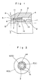
- La Fig. 1 est une vue partielle en coupe longitudinale de l'extrémité de la buse selon un premier mode de réalisation,
- La Fig. 2 est une vue latérale en élévation de la buse, selon la ligne II-II de la Fig. 1,
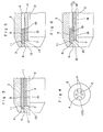
- La Fig. 3 est une vue partielle en coupe longitudinale de l'extrémité de la buse selon un second mode de réalisation,
- La Fig. 4 est une vue latérale en élévation de la buse selon le mode de réalisation de la Fig. 3,
- La Fig. 5 est une vue partielle en coupe longitudinale de la buse selon un troisième mode de réalisation et,
- La Fig. 6 est une vue partielle en coupe longitudinale de la buse selon un quatrième mode de réalisation.
- Fig. 1 is a partial view in longitudinal section of the end of the nozzle according to a first embodiment,
- Fig. 2 is a side view in elevation of the nozzle, along the line II-II of FIG. 1,
- Fig. 3 is a partial view in longitudinal section of the end of the nozzle according to a second embodiment,
- Fig. 4 is a side view in elevation of the nozzle according to the embodiment of FIG. 3,
- Fig. 5 is a partial view in longitudinal section of the nozzle according to a third embodiment and,
- Fig. 6 is a partial view in longitudinal section of the nozzle according to a fourth embodiment.
La structure commune aux quatre modes de réalisation représentés sur les dessins joints est décrite en se référant aux Figures 1 à 6.The structure common to the four embodiments shown in the accompanying drawings is described with reference to Figures 1 to 6.
Un tube extérieur électro-conducteur (3) est monté sur un tube intérieur élecro-conducteur (1) et isolé électriquement de celui-ci. Le tube extérieur (3) fait saillie en avant au-delà du tube intérieur (1). Un organe isolant électrique (5) est monté au moins dans la partie d'extrémité avant du tube extérieur (3) et sa face frontale (9) est disposée en avant de la face frontale (7) du tube intérieur (1). La surface intérieure de la partie d'extrémité avant du tube extérieur (3) et la partie d'extrémité avant de la surface intérieure (10) de l'organe isolant (5) définissent une surface en jupe (6). L'extrémité arrière (11) de la partie d'extrémité avant du tube extérieur définissant la surface en jupe (6) et la face frontale (7) du tube intérieur (1) constituent une paire d'électrodes à étincelles (12, 13).An electrically conductive outer tube (3) is mounted on an electrically conductive inner tube (1) and electrically insulated therefrom. The outer tube (3) projects forward beyond the inner tube (1). An electrical insulating member (5) is mounted at least in the front end part of the outer tube (3) and its front face (9) is arranged in front of the front face (7) of the inner tube (1). The inner surface of the front end part of the outer tube (3) and the front end part of the inner surface (10) of the insulating member (5) define a skirted surface (6). The rear end (11) of the front end part of the outer tube defining the skirt surface (6) and the front face (7) of the inner tube (1) constitute a pair of spark electrodes (12, 13 ).
Dans la structure décrite ci-dessus, les étincelles sont produites en un emplacement situé en avant de la sortie du mélange gazeux, c'est-à-dire en avant de la face frontale (7) du tube intérieur afin que le mélange gazeux puisse s'enflammer de façon plus sûre que lorsque les étincelles sont produites en un emplacement coïncidant exactement avec la face frontale (7) ou à l'arrière (vers l'intérieur) de celle-ci.In the structure described above, the sparks are produced at a location located in front of the outlet of the gas mixture, that is to say in front of the front face (7) of the inner tube so that the gas mixture can ignite more safely than when sparks are produced at a location exactly coinciding with the front face (7) or at the rear (inwards) thereof.
L'organe isolant (5) qui est essentiel pour limiter l'emplacement de la formation des étincelles uniquement à l'extrémité de la buse, comme indiqué plus haut, est disposé de manière adéquate de manière à provoquer la formation des étincelles en avant de la sortie du mélange gazeux. En conséquence, la structure est simple et commode à réaliser.The insulating member (5) which is essential to limit the location of the formation of sparks only at the end of the nozzle, as indicated above, is suitably arranged so as to cause the formation of sparks before the outlet of the gas mixture. As a result, the structure is simple and convenient to make.
La présente invention a donc l'avantage de pouvoir assurer un allumage adéquat à l'aide d'une structure simple.The present invention therefore has the advantage of being able to ensure adequate ignition using a simple structure.
Un premier mode de réalisation de l'invention va maintenant être décrit en se référant aux Fig. 1 et 2. Les dispositions de la structure commune déjà décrites ne seront pas reprises dans cette description.A first embodiment of the invention will now be described with reference to FIGS. 1 and 2. The provisions of the common structure already described will not be repeated in this description.
Le tube intérieur (1) et le tube extérieur (3) sont tous deux en cuivre. On fait passer un mélange de gaz propane et d'oxygène de préchauffage dans un canal de passage annulaire (4) prévu entre les tubes (1) et (3). L'organe isolant électrique (5) est en céramique. La surface intérieure (10) de l'organe isolant (5) fait face à une partie du canal (4) constituée par plusieurs rainures (14) ménagées par usinage sur la périphérie extérieure du tube intérieur (1), et dans le sens de l'axe dudit tube (1). Les rainures (14) sont disposées à intervalles égaux sur la périphérie du tube (1).The inner tube (1) and the outer tube (3) are both made of copper. We pass a mixture of propane and oxygen from preheating in an annular passage channel (4) provided between the tubes (1) and (3). The electrical insulating member (5) is made of ceramic. The inner surface (10) of the insulating member (5) faces a part of the channel (4) constituted by several grooves (14) formed by machining on the outer periphery of the inner tube (1), and in the direction of the axis of said tube (1). The grooves (14) are arranged at equal intervals on the periphery of the tube (1).
Bien que la surface intérieure (10) de l'organe isolant et la surface en jupe (6) aient été représentées de façon à affleurer l'une l'autre, il est possible de les déplacer l'une par rapport à l'autre, vers l'intérieur ou l'extérieur, dans le sens radial.Although the inner surface (10) of the insulating member and the skirted surface (6) have been represented so as to be flush with each other, it is possible to move them relative to each other , inwards or outwards, in the radial direction.
Il est préférable d'utiliser un bloc piézo-électrique comme alimentation électrique, mais il n'a pas été représenté. Bien que l'on puisse utiliser l'énergie de l'oxygène de coupe à haute pression pour commander le bloc piézo-électrique, on peut également utiliser en variante une force de percussion mécanique ou manuelle ou une force de compression. Le bloc piézo-électrique peut être monté dans la tête de chalumeau ou de torche ou dans la buse. Outre le bloc piézo-électrique, il est également possible d'utiliser une batterie ou l'alimentation du réseau.It is preferable to use a piezoelectric block as a power supply, but it has not been shown. Although the energy of cutting oxygen at high pressure can be used to control the piezoelectric block, alternatively a mechanical or manual percussive force or a compressive force can also be used. The piezoelectric block can be mounted in the torch or torch head or in the nozzle. In addition to the piezoelectric block, it is also possible to use a battery or the mains supply.
Une second mode de réalisation va maintenant être décrit en se référant aux Fig. 3 et 4.A second embodiment will now be described with reference to Figs. 3 and 4.
Plusieurs canaux de passage de mélange gazeux (4) traversent le tube intérieur (1) sur toute sa longueur. L'organe isolant (5) est interposé entre le tube intérieur (1) et le tube extérieur (3), sur toute l'étendue sur laquelle ces deux organes sont en regard.Several gas mixture passage channels (4) pass through the inner tube (1) over its entire length. The insulating member (5) is interposed between the inner tube (1) and the outer tube (3), over the entire extent over which these two members are opposite.
Un troisième mode de réalisation va maintenant être décrit en se référant à la Fig. 5. Un canal annulaire de mélange gazeux (4) est ménagé entre le tube intérieur (1) et le tube extérieur (3), comme dans le cas du premier mode de réalisation, mais la face frontale du canal (4) est fermée par l'organe isolant (5). Plusieurs canaux de passage de mélange gazeux (15), communiquant avec le canal annulaire (4), s'étendent à travers la partie d'extrémité avant du tube intérieur (1).A third embodiment will now be described with reference to FIG. 5. An annular gas mixture channel (4) is formed between the inner tube (1) and the outer tube (3), as in the case of the first embodiment, but the front face of the channel (4) is closed by the insulating member (5). A plurality of gas mixture passage channels (15), communicating with the annular channel (4), extend through the front end portion of the inner tube (1).
La Fig. 6 représente un quatrième mode de réalisation. Le tube intérieur (1) est subdivisé en deux tubes, l'un externe (17) et l'autre interne (16). Le tube intérieur interne (16) et le tube intérieur externe (17) sont assemblés et un canal annulaire de passage de mélange gazeux (18) est ménagé entre eux deux, sauf à leurs parties d'extrémité avant. Plusieurs canaux de passage de mélange gazeux en forme de rainures (19), communiquant avec la rainure annulaire (18), sont ménagés sur la périphérie extérieure de la partie d'extrémité avant du tube intérieur interne (16), dans le sens de l'axe dudit tube (16).Fig. 6 shows a fourth embodiment. The inner tube (1) is subdivided into two tubes, one external (17) and the other internal (16). The inner inner tube (16) and the inner tube external (17) are assembled and an annular gas passage passage channel (18) is formed between them, except at their front end parts. Several groove-shaped gas mixture passage channels (19), communicating with the annular groove (18), are provided on the outer periphery of the front end part of the inner inner tube (16), in the direction of the axis of said tube (16).
Claims (5)
Applications Claiming Priority (2)
| Application Number | Priority Date | Filing Date | Title |
|---|---|---|---|
| JP5900082A JPS57179660A (en) | 1981-04-10 | 1982-04-10 | Method and means for detecting pneumonia coccus x iv antigen in sample of human cell |
| JP59000/82 | 1982-04-21 |
Publications (2)
| Publication Number | Publication Date |
|---|---|
| EP0092490A2 true EP0092490A2 (en) | 1983-10-26 |
| EP0092490A3 EP0092490A3 (en) | 1984-03-28 |
Family
ID=13100584
Family Applications (1)
| Application Number | Title | Priority Date | Filing Date |
|---|---|---|---|
| EP83400789A Withdrawn EP0092490A3 (en) | 1982-04-10 | 1983-04-21 | Nozzle with spark ignition |
Country Status (2)
| Country | Link |
|---|---|
| EP (1) | EP0092490A3 (en) |
| FR (1) | FR2525738A1 (en) |
Family Cites Families (2)
| Publication number | Priority date | Publication date | Assignee | Title |
|---|---|---|---|---|
| FR1343579A (en) * | 1962-09-04 | 1963-11-22 | Harris Calorific Co | Lighter torch |
| US3540656A (en) * | 1968-03-08 | 1970-11-17 | Goss Gas Inc | Torch tips |
-
1983
- 1983-04-21 FR FR8306533A patent/FR2525738A1/en active Pending
- 1983-04-21 EP EP83400789A patent/EP0092490A3/en not_active Withdrawn
Also Published As
| Publication number | Publication date |
|---|---|
| EP0092490A3 (en) | 1984-03-28 |
| FR2525738A1 (en) | 1983-10-28 |
Similar Documents
| Publication | Publication Date | Title |
|---|---|---|
| EP0689007B1 (en) | Cooling the take-off injector in a combustion chamber with two burner heads | |
| CA2649998C (en) | Arrangement of a semi-conductor-type spark plug in a combustion chamber of a gas turbine engine | |
| FR2507682A1 (en) | PRECOMBUSTION CHAMBER IN A CYLINDER HEAD OF A DIESEL ENGINE | |
| EP3969735B1 (en) | Engine with an ignition insert with active prechamber | |
| EP1770332A1 (en) | Device for guiding an element into an orifice of a gas turbine combustion chamber wall | |
| CA1200689A (en) | Hot gunite lance nozzle | |
| CA2639231C (en) | Improved internal combustion gas-powered hand tool | |
| FR2644558A1 (en) | Arc furnace equipped with fuel oil/oxygen burners and fuel oil/oxygen burner | |
| EP0092490A2 (en) | Nozzle with spark ignition | |
| WO1998059199A1 (en) | Gas appliance such as a thermal weed sprayer | |
| CA2016471A1 (en) | Oxygen cutting tip | |
| FR2536506A1 (en) | FUEL PREPARATION DEVICE, LIKELY TO BE CARRIED AT HIGH TEMPERATURE, PARTICULARLY FOR GASIFICATION BURNERS SUPPLIED WITH LIQUID FUEL, AND METHOD FOR MANUFACTURING THE DEVICE | |
| EP0093053A2 (en) | Torch with spark ignition | |
| WO1999034105A1 (en) | Acoustic igniter and ignition method for propellant liquid rocket engine | |
| FR2740272A1 (en) | Ignition device with sealing joint for internal combustion engine | |
| EP0427591B1 (en) | Plasma torch with non-cooled plasma gas injection | |
| EP0102907A2 (en) | Torch with spark ignition | |
| EP0368829B1 (en) | Solid-fuel burner | |
| FR2622745A1 (en) | Spark igniter for jet engine, with floating positioning | |
| WO1991001077A1 (en) | Plasma torch | |
| EP0093047A2 (en) | Torch nozzle with spark ignition | |
| FR2719361A1 (en) | Improvements to gas burners. | |
| FR2735940A1 (en) | PLASMA TORCH WITH GENERAL STRUCTURE SENSIBLY AXI-SYMMETRIC | |
| FR2525739A1 (en) | SPARK IGNITION TYPE TORCH | |
| EP0093642A2 (en) | Nozzle with spark ignition |
Legal Events
| Date | Code | Title | Description |
|---|---|---|---|
| PUAI | Public reference made under article 153(3) epc to a published international application that has entered the european phase |
Free format text: ORIGINAL CODE: 0009012 |
|
| 17P | Request for examination filed |
Effective date: 19830425 |
|
| AK | Designated contracting states |
Designated state(s): AT BE CH DE FR GB IT LI LU NL SE |
|
| PUAL | Search report despatched |
Free format text: ORIGINAL CODE: 0009013 |
|
| AK | Designated contracting states |
Designated state(s): AT BE CH DE FR GB IT LI LU NL SE |
|
| STAA | Information on the status of an ep patent application or granted ep patent |
Free format text: STATUS: THE APPLICATION IS DEEMED TO BE WITHDRAWN |
|
| 18D | Application deemed to be withdrawn |
Effective date: 19840929 |
|
| RIN1 | Information on inventor provided before grant (corrected) |
Inventor name: KUBOTA, YOSINORI |