EP0092518B1 - Elément de touche - Google Patents
Elément de touche Download PDFInfo
- Publication number
- EP0092518B1 EP0092518B1 EP83810149A EP83810149A EP0092518B1 EP 0092518 B1 EP0092518 B1 EP 0092518B1 EP 83810149 A EP83810149 A EP 83810149A EP 83810149 A EP83810149 A EP 83810149A EP 0092518 B1 EP0092518 B1 EP 0092518B1
- Authority
- EP
- European Patent Office
- Prior art keywords
- stem
- base
- key element
- wall
- circuit board
- Prior art date
- Legal status (The legal status is an assumption and is not a legal conclusion. Google has not performed a legal analysis and makes no representation as to the accuracy of the status listed.)
- Expired
Links
- 230000005294 ferromagnetic effect Effects 0.000 claims abstract description 10
- 238000005476 soldering Methods 0.000 claims abstract description 3
- 229920003023 plastic Polymers 0.000 claims description 9
- 238000006073 displacement reaction Methods 0.000 claims description 3
- 230000037431 insertion Effects 0.000 claims 2
- 238000003780 insertion Methods 0.000 claims 2
- 239000000463 material Substances 0.000 claims 1
- 238000005507 spraying Methods 0.000 description 3
- 230000001419 dependent effect Effects 0.000 description 2
- 238000002347 injection Methods 0.000 description 2
- 239000007924 injection Substances 0.000 description 2
- 238000009434 installation Methods 0.000 description 2
- 238000000034 method Methods 0.000 description 2
- 230000000149 penetrating effect Effects 0.000 description 2
- 230000000630 rising effect Effects 0.000 description 2
- 238000011161 development Methods 0.000 description 1
- 230000018109 developmental process Effects 0.000 description 1
- 238000005516 engineering process Methods 0.000 description 1
- 239000007788 liquid Substances 0.000 description 1
- 238000012423 maintenance Methods 0.000 description 1
- 238000004519 manufacturing process Methods 0.000 description 1
- 230000000284 resting effect Effects 0.000 description 1
- 239000007921 spray Substances 0.000 description 1
- 238000004804 winding Methods 0.000 description 1
Images


Classifications
-
- H—ELECTRICITY
- H03—ELECTRONIC CIRCUITRY
- H03K—PULSE TECHNIQUE
- H03K17/00—Electronic switching or gating, i.e. not by contact-making and –breaking
- H03K17/94—Electronic switching or gating, i.e. not by contact-making and –breaking characterised by the way in which the control signals are generated
- H03K17/965—Switches controlled by moving an element forming part of the switch
- H03K17/97—Switches controlled by moving an element forming part of the switch using a magnetic movable element
- H03K17/972—Switches controlled by moving an element forming part of the switch using a magnetic movable element having a plurality of control members, e.g. keyboard
Definitions
- the present invention relates to a key element according to the preamble of the first claim.
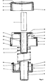
- the key element consists of a base 1, a plunger 2, a spherical cap 3, a ferromagnetic core 4 and a spring element 5 or 5 '.
- the individual parts 1, 2 and 3 are made of plastic, advantageously by spraying.
- Fig. 1 shows the base 1 in plan, while the bottom element of the exploded view of Fig. 4 shows the base in a sectional side view and Fig. 6 shows this partially cut with the details of its attachment to a circuit board 6.
- the base 1 consists essentially of an upwardly open box with walls 12, which box has a square plan view as a whole, and of a cylindrical tube 18 formed in the bottom 11 of the box, the bottom of which is closed.
- arms 13 are formed on the free, upper end of the walls 12 and extend downwards, as can be seen clearly from FIG. 6. These arms are resilient and extend down almost the same distance as the tube 18.
- At the lower ends of the arms there are wedge-shaped widenings 13 'with a gently rising front and a steeply falling back.
- hollow cylindrical segment-shaped projections 14 are formed on the bottom 11, the lower ends of which are chamfered on the convex side.
- the projections 14 serve to prevent rotation of the key element when it is installed in a printed circuit board 6, which must have three bores per key element, namely a bore 61 for the passage of the tube 18 and the ferromagnetic core 4 which can be displaced therein, as will be explained later, and two bores 62 for the projections 14, the cylinder radius of which corresponds approximately to the radius of the bores 62.
- the resilient arms 13 can be introduced into the part of the bores 62 which is not occupied by the projections 14, the gently rising front side of their end widenings 13 ′ being like also the bevelling of the ends of the projections 14 facilitate the introduction of the base or a key element built thereon into the printed circuit board.
- the steep rear side of the end widenings 13 ′ causes the key element to be fixed on the circuit board in a manner that can be released without the use of tools and takes up the thickness tolerances of the circuit board.
- niches 17 just below the upper ends thereof, which serve for receiving the ends of a leaf spring 5 'for resetting the plunger, which is shaped in a meandering manner between the niches 17 and the underside of the cover 26 of the plunger 2 that there is a pressure point when the button is pressed.
- the connecting lines between corresponding niches on opposite walls 12 run at an angle deviating from 90 ° to the right side wall and the axis of the cylindrical tube 18 does not run through the diagonal intersection of the imaginary floor plan square of the base, but somewhat above.
- this saves space for the leaf spring, and on the other hand, due to the opposite offset, visible from FIG. 2, between the tappet tube 21 and the spherical seat 2 ", the point of contact of the leaf spring 5 'on the tappet is only slightly offset from the center of the spherical head.
- the base is designed both to accommodate a coil spring with a linear displacement / force characteristic and for a leaf spring with a non-linear displacement / force characteristic, depending on the wishes of the user.
- the wall of the base 1 lying at the bottom in FIG. 1 has a wall region with a smaller wall thickness, in the middle of which there is an outwardly pointing projection 16 which extends upwards beyond the wall 12, as can be seen in FIG. 4 .
- This projection together with an opposite projection 23 'on an arm 23 formed on the plunger 2, causes a stop for the upward movement of the plunger caused by the return spring 5 or 5'.
- the two projections slide with their opposite bevels on one another under resilient deflection in order to finally engage, as shown in FIG. 5.
- the plunger and the base are captively but detachably connected to one another.
- the base 1 as a one-piece plastic part contains all the elements necessary for guiding and limiting the stroke of the plunger, for the tool-free and solderless installation and removal of a key element and for accommodating return springs with different travel / force characteristics are.
- the actual dimensions of the imaginary floor plan square of the base are approximately 12 x 12 mm, so that the base can be used for key elements with a grid size of 15 x 15 mm.
- the smallest grid dimension is used for so-called management keyboards, whereas larger grid dimensions are usual for professional keyboards.
- Fig. 2 shows the ram 2 in plan, while the central element in the exploded view of Fig. 4 shows this in section.
- the plunger 2 consists essentially of a lower wall part 2 'with a square or rectangular plan, the mass and shape of which are determined by the grid dimension of the keyboard desired by the user, from an intermediate floor 22, from an upper wall part 2 "with a circular plan, from one Cover 26 and from a cylindrical tube 21 formed on the latter with closed lower and open upper end.
- the already mentioned cylindrical tube 21, the lower end of which is closed, is formed on the underside of the cover 26 that closes off the cylindrical wall part 2 ". Its interior accommodates the ferromagnetic core 4, which is fixed, for example, by heat deformation of the outlet edge of the tube. Similar to the tube 18 of the base, the tube 21 also has a lower part with smooth walls of relatively small wall thickness and an upper part with a number of ribs 25 formed on the outer surface, which end in triangular struts 28 near the cover 26, which As already mentioned, serve to center the helical spring 5. When the button is pressed, the ribs 25 slide in the grooves 19 of the base and thus provide protection against the rotation of the plunger in the base and reinforce the tube 21.
- these ribs enlarge the flow cross section from the injection point in the bottom of the tube 21 to the side walls 2 "and 2 '.
- the play between the ribs 25 and the grooves 19 causes a simple escape of the air displaced from the tube 18 when the button is pressed.
- a corner of the side wall 12 of the base 1 has a groove 12 'visible in FIG. 1, while the wall thickness of the square or rectangular part 2' of the side wall of the plunger 2 is smaller at point 29, as can be seen from FIG. 2 .
- These two measures together with a hole (not shown) in the intermediate floor 22, which is closed by a translucent cover, serve to provide the possibility of installing a light-emitting diode soldered into the circuit board as a control lamp, as is sometimes desired for special keys.
- the air gap between the ferromagnetic core 4 and the windings of the key transformer is hardly larger than in an arrangement with those mentioned in the prior art Keys in which arrangement the core passes through the circuit board without being exposed, but because of the manufacturing tolerances a relatively large through hole must be selected.
- the calotte can be made of transparent plastic.
- a label can be inserted in the space visible in FIG. 5 between the plunger and the separable underside of the calotte, which can offer an advantage for prototype keyboards.
- the spherical caps and their names are more likely to be produced using the two-color spray process.
- this mold process requires a separate tool cavity for each character, it is very important that the shape of the part to be manufactured is as simple as possible.
Landscapes
- Push-Button Switches (AREA)
- Input From Keyboards Or The Like (AREA)
- Oscillators With Electromechanical Resonators (AREA)
- Electronic Switches (AREA)
Claims (11)
Priority Applications (1)
| Application Number | Priority Date | Filing Date | Title |
|---|---|---|---|
| AT83810149T ATE30131T1 (de) | 1982-04-15 | 1983-04-13 | Tastenelement. |
Applications Claiming Priority (2)
| Application Number | Priority Date | Filing Date | Title |
|---|---|---|---|
| CH228282 | 1982-04-15 | ||
| CH2282/82 | 1982-04-15 |
Publications (3)
| Publication Number | Publication Date |
|---|---|
| EP0092518A2 EP0092518A2 (fr) | 1983-10-26 |
| EP0092518A3 EP0092518A3 (en) | 1984-11-28 |
| EP0092518B1 true EP0092518B1 (fr) | 1987-10-07 |
Family
ID=4230122
Family Applications (1)
| Application Number | Title | Priority Date | Filing Date |
|---|---|---|---|
| EP83810149A Expired EP0092518B1 (fr) | 1982-04-15 | 1983-04-13 | Elément de touche |
Country Status (6)
| Country | Link |
|---|---|
| US (1) | US4791257A (fr) |
| EP (1) | EP0092518B1 (fr) |
| JP (1) | JPS5916225A (fr) |
| AT (1) | ATE30131T1 (fr) |
| CA (1) | CA1204841A (fr) |
| DE (1) | DE3373990D1 (fr) |
Families Citing this family (15)
| Publication number | Priority date | Publication date | Assignee | Title |
|---|---|---|---|---|
| US5449870A (en) * | 1992-02-28 | 1995-09-12 | Lucerne Products, Inc. | Switch actuating assembly having attachable trigger |
| US5676476A (en) * | 1995-12-14 | 1997-10-14 | Uke; Alan K. | Method and apparatus for preventing injury to an electronic computer keyboard operator |
| US6791480B1 (en) * | 1998-12-04 | 2004-09-14 | Alan K. Uke | Method of preventing and/or alleviating repetitive use injury to electronic computer keyboard operator |
| JP2003085721A (ja) * | 2001-09-14 | 2003-03-20 | Mitsumi Electric Co Ltd | ヘッド送り機構 |
| US7158008B2 (en) * | 2002-03-29 | 2007-01-02 | Datakey Electronincs, Inc. | Electronic key system and method |
| US7038598B2 (en) * | 2002-05-29 | 2006-05-02 | Alan K. Uke | Keyboard assemblies |
| US20040085716A1 (en) * | 2002-11-05 | 2004-05-06 | Uke Alan K. | Modular keyboard system |
| USD557588S1 (en) | 2006-08-23 | 2007-12-18 | Datakey Electronics, Inc. | Electronic key |
| US7696741B2 (en) * | 2007-04-27 | 2010-04-13 | Korry Electronics, Co. | System and method for adaptively determining the transition rate of a quantized signal |
| US7994886B2 (en) * | 2007-05-17 | 2011-08-09 | Korry Electronics Co. | Fault tolerant solid state push button control system with built in diagnostic |
| USD649894S1 (en) | 2008-12-30 | 2011-12-06 | Atek Products, Llc | Electronic token and data carrier |
| USD649896S1 (en) | 2009-01-30 | 2011-12-06 | Atek Products, Llc | Electronic token and data carrier receptacle |
| WO2010088556A1 (fr) | 2009-01-30 | 2010-08-05 | Datakey Electronics, Inc. | Système de support de données ayant une empreinte compacte et procédés de fabrication de celui-ci |
| USD649895S1 (en) | 2009-01-30 | 2011-12-06 | Atek Products, Llc | Electronic token and data carrier |
| USD649486S1 (en) | 2009-07-09 | 2011-11-29 | ATEK Products , LLC | Electronic token and data carrier |
Family Cites Families (17)
| Publication number | Priority date | Publication date | Assignee | Title |
|---|---|---|---|---|
| US3668697A (en) * | 1970-09-24 | 1972-06-06 | Hewlett Packard Co | Noncontacting keyboard |
| GB1376691A (en) * | 1971-12-01 | 1974-12-11 | Int Standard Electric Corp | Photoelectric pushbutton switch |
| US3749859A (en) * | 1972-04-19 | 1973-07-31 | Colorado Instr Inc | Keyboard switch assembly with improved hermetically sealed diaphragm contact structure |
| US3858145A (en) * | 1972-06-19 | 1974-12-31 | Ibm | Magnetic circuit device for a contactless switch or the like |
| DE2233170A1 (de) * | 1972-07-06 | 1974-01-17 | Triumph Werke Nuernberg Ag | Tastschalter mit einem in einem gehaeuse verschiebbaren tastenstoessel |
| US3826884A (en) * | 1973-06-25 | 1974-07-30 | Oak Industries Inc | Keyboard switch |
| US4202640A (en) * | 1974-08-22 | 1980-05-13 | Kienzle Apparate Gmbh | Keyboard assembly |
| GB1521435A (en) * | 1977-02-24 | 1978-08-16 | Ibm Uk | Keyboard button manufacture |
| SU636717A1 (ru) * | 1977-04-15 | 1978-12-05 | Предприятие П/Я В-8543 | Бесконтактный переключатель |
| US4300127A (en) * | 1978-09-27 | 1981-11-10 | Bernin Victor M | Solid state noncontacting keyboard employing a differential transformer element |
| US4268814A (en) * | 1978-10-26 | 1981-05-19 | Texas Instruments Incorporated | Solid state keyboard |
| DE2848741A1 (de) * | 1978-11-10 | 1980-05-22 | Standard Elektrik Lorenz Ag | Druckknopf fuer tastschalter |
| US4227163A (en) * | 1979-03-05 | 1980-10-07 | Illinois Tool Works Inc. | Electrical keyswitch |
| GB2046996A (en) * | 1979-04-11 | 1980-11-19 | Electronic Components Ltd | Electrical switch |
| DE2932623A1 (de) * | 1979-08-11 | 1981-02-19 | Mergenthaler Linotype Gmbh | Tastatur mit einem ueberdecker ueber wenigstens einer taste, insbesondere eines textbearbeitungs- und/oder fotosatzgeraets |
| NL7906931A (nl) * | 1979-09-18 | 1981-03-20 | Philips Nv | Druktoetsschakelaar. |
| DE2943855C2 (de) * | 1979-10-30 | 1982-10-21 | Siemens AG, 1000 Berlin und 8000 München | Drucktaste |
-
1983
- 1983-04-13 AT AT83810149T patent/ATE30131T1/de not_active IP Right Cessation
- 1983-04-13 DE DE8383810149T patent/DE3373990D1/de not_active Expired
- 1983-04-13 EP EP83810149A patent/EP0092518B1/fr not_active Expired
- 1983-04-14 US US06/484,804 patent/US4791257A/en not_active Expired - Fee Related
- 1983-04-14 CA CA000425891A patent/CA1204841A/fr not_active Expired
- 1983-04-15 JP JP58065734A patent/JPS5916225A/ja active Pending
Also Published As
| Publication number | Publication date |
|---|---|
| EP0092518A3 (en) | 1984-11-28 |
| ATE30131T1 (de) | 1987-10-15 |
| DE3373990D1 (en) | 1987-11-12 |
| JPS5916225A (ja) | 1984-01-27 |
| US4791257A (en) | 1988-12-13 |
| CA1204841A (fr) | 1986-05-20 |
| EP0092518A2 (fr) | 1983-10-26 |
Similar Documents
| Publication | Publication Date | Title |
|---|---|---|
| EP0092518B1 (fr) | Elément de touche | |
| DE3007239C2 (de) | Tastatur mit einer Vielzahl von Tastengliedern | |
| DE3031196A1 (de) | Beleuchteter druckknopfschalter | |
| DE1293286B (de) | Beleuchteter Druckknopf-Schaltmechanismus | |
| DE2848741A1 (de) | Druckknopf fuer tastschalter | |
| DE3414909A1 (de) | Tastschalter | |
| DE2616854C2 (de) | Vorrichtung zum Umschalten einer elektrischen Schaltung | |
| DE2131336A1 (de) | Druckknopfschalter | |
| DE4410201C2 (de) | Quadranten-Schalter | |
| DE3109401C2 (fr) | ||
| EP0678885B1 (fr) | Touche électrique | |
| DE3107316C2 (fr) | ||
| DE102009049407B4 (de) | Elektroinstallationsgerät mit einstellbarem Schaltelement | |
| DE3240940A1 (de) | Taste zum schliessen elektrischer kontakte | |
| WO2007107532A1 (fr) | Bouton poussoir avec guidage amélioré du bouton | |
| DE1665299A1 (de) | Drucktastenschalter | |
| DE3545879C2 (de) | Abgedichteter Drucktastenschalter, insb. in Schmalbauweise | |
| DE7541273U (de) | Schalter | |
| DE3107440A1 (de) | Elektrischer schalter, insbesondere zur anordnung im schalthebelende eines lenkstockschalters | |
| DE3411597A1 (de) | Schiebeschalter | |
| DE3111407A1 (de) | Tastenschalter | |
| DE3214241C2 (de) | Schalter, insbesondere zum Einbau in Montageplatten | |
| EP1482527A1 (fr) | Interrupteur à bouton poussoir | |
| DE3143996A1 (de) | Elektrischer miniaturschalter | |
| DE2924782C2 (fr) |
Legal Events
| Date | Code | Title | Description |
|---|---|---|---|
| PUAI | Public reference made under article 153(3) epc to a published international application that has entered the european phase |
Free format text: ORIGINAL CODE: 0009012 |
|
| AK | Designated contracting states |
Designated state(s): AT BE CH DE FR GB IT LI NL SE |
|
| RAP1 | Party data changed (applicant data changed or rights of an application transferred) |
Owner name: INTERNATIONAL STANDARD ELECTRIC CORPORATION Owner name: STANDARD TELEPHON UND RADIO AG |
|
| 17P | Request for examination filed |
Effective date: 19840315 |
|
| PUAL | Search report despatched |
Free format text: ORIGINAL CODE: 0009013 |
|
| AK | Designated contracting states |
Designated state(s): AT BE CH DE FR GB IT LI NL SE |
|
| GRAA | (expected) grant |
Free format text: ORIGINAL CODE: 0009210 |
|
| RAP1 | Party data changed (applicant data changed or rights of an application transferred) |
Owner name: ALCATEL N.V. Owner name: STANDARD TELEPHON UND RADIO AG |
|
| AK | Designated contracting states |
Kind code of ref document: B1 Designated state(s): AT BE CH DE FR GB IT LI NL SE |
|
| REF | Corresponds to: |
Ref document number: 30131 Country of ref document: AT Date of ref document: 19871015 Kind code of ref document: T |
|
| ITF | It: translation for a ep patent filed | ||
| REF | Corresponds to: |
Ref document number: 3373990 Country of ref document: DE Date of ref document: 19871112 |
|
| ET | Fr: translation filed | ||
| RAP4 | Party data changed (patent owner data changed or rights of a patent transferred) |
Owner name: ALCATEL N.V. Owner name: STANDARD TELEPHON UND RADIO AG |
|
| PLBI | Opposition filed |
Free format text: ORIGINAL CODE: 0009260 |
|
| 26 | Opposition filed |
Opponent name: MANNESMANN KIENZLE GMBH Effective date: 19880623 |
|
| NLR1 | Nl: opposition has been filed with the epo |
Opponent name: MANNESMANN KIENZLE GMBH |
|
| BERE | Be: lapsed |
Owner name: ALCATEL N.V. Effective date: 19880430 |
|
| PGFP | Annual fee paid to national office [announced via postgrant information from national office to epo] |
Ref country code: BE Payment date: 19890126 Year of fee payment: 6 |
|
| PG25 | Lapsed in a contracting state [announced via postgrant information from national office to epo] |
Ref country code: LI Free format text: LAPSE BECAUSE OF NON-PAYMENT OF DUE FEES Effective date: 19890430 Ref country code: FR Free format text: LAPSE BECAUSE OF NON-PAYMENT OF DUE FEES Effective date: 19890430 Ref country code: CH Free format text: LAPSE BECAUSE OF NON-PAYMENT OF DUE FEES Effective date: 19890430 Ref country code: BE Effective date: 19890430 |
|
| PGFP | Annual fee paid to national office [announced via postgrant information from national office to epo] |
Ref country code: GB Payment date: 19890430 Year of fee payment: 7 |
|
| BERE | Be: lapsed |
Owner name: ALCATEL N.V. Effective date: 19890430 |
|
| PG25 | Lapsed in a contracting state [announced via postgrant information from national office to epo] |
Ref country code: NL Effective date: 19891101 |
|
| NLV4 | Nl: lapsed or anulled due to non-payment of the annual fee | ||
| REG | Reference to a national code |
Ref country code: CH Ref legal event code: PL |
|
| BERR | Be: reestablished |
Owner name: *ALCATEL N.V. Effective date: 19890113 |
|
| PG25 | Lapsed in a contracting state [announced via postgrant information from national office to epo] |
Ref country code: DE Effective date: 19900103 |
|
| PGFP | Annual fee paid to national office [announced via postgrant information from national office to epo] |
Ref country code: AT Payment date: 19900412 Year of fee payment: 8 |
|
| PG25 | Lapsed in a contracting state [announced via postgrant information from national office to epo] |
Ref country code: GB Effective date: 19900413 |
|
| PGFP | Annual fee paid to national office [announced via postgrant information from national office to epo] |
Ref country code: SE Payment date: 19900419 Year of fee payment: 8 |
|
| RAP2 | Party data changed (patent owner data changed or rights of a patent transferred) |
Owner name: ALCATEL N.V. Owner name: ALCATEL STR AG |
|
| RDAG | Patent revoked |
Free format text: ORIGINAL CODE: 0009271 |
|
| STAA | Information on the status of an ep patent application or granted ep patent |
Free format text: STATUS: PATENT REVOKED |
|
| GBPC | Gb: european patent ceased through non-payment of renewal fee | ||
| 27W | Patent revoked |
Effective date: 19900728 |
|
| GBPR | Gb: patent revoked under art. 102 of the ep convention designating the uk as contracting state | ||
| EUG | Se: european patent has lapsed |
Ref document number: 83810149.1 Effective date: 19901227 |