EP0092523A1 - Schaltungsanordnung zur Programmsteuerung einer Maschine - Google Patents
Schaltungsanordnung zur Programmsteuerung einer Maschine Download PDFInfo
- Publication number
- EP0092523A1 EP0092523A1 EP83810155A EP83810155A EP0092523A1 EP 0092523 A1 EP0092523 A1 EP 0092523A1 EP 83810155 A EP83810155 A EP 83810155A EP 83810155 A EP83810155 A EP 83810155A EP 0092523 A1 EP0092523 A1 EP 0092523A1
- Authority
- EP
- European Patent Office
- Prior art keywords
- program
- commands
- main control
- control
- transmitter
- Prior art date
- Legal status (The legal status is an assumption and is not a legal conclusion. Google has not performed a legal analysis and makes no representation as to the accuracy of the status listed.)
- Granted
Links
Images



Classifications
-
- G—PHYSICS
- G05—CONTROLLING; REGULATING
- G05B—CONTROL OR REGULATING SYSTEMS IN GENERAL; FUNCTIONAL ELEMENTS OF SUCH SYSTEMS; MONITORING OR TESTING ARRANGEMENTS FOR SUCH SYSTEMS OR ELEMENTS
- G05B19/00—Program-control systems
- G05B19/02—Program-control systems electric
- G05B19/04—Program control other than numerical control, i.e. in sequence controllers or logic controllers
- G05B19/12—Program control other than numerical control, i.e. in sequence controllers or logic controllers using record carriers
- G05B19/14—Program control other than numerical control, i.e. in sequence controllers or logic controllers using record carriers using punched cards or tapes
-
- G—PHYSICS
- G05—CONTROLLING; REGULATING
- G05B—CONTROL OR REGULATING SYSTEMS IN GENERAL; FUNCTIONAL ELEMENTS OF SUCH SYSTEMS; MONITORING OR TESTING ARRANGEMENTS FOR SUCH SYSTEMS OR ELEMENTS
- G05B19/00—Program-control systems
- G05B19/02—Program-control systems electric
- G05B19/04—Program control other than numerical control, i.e. in sequence controllers or logic controllers
- G05B19/10—Program control other than numerical control, i.e. in sequence controllers or logic controllers using selector switches
Definitions
- the present invention relates to a method for program control of a machine, in particular a washing machine, according to the preamble of independent patent claim 1, a circuit arrangement for carrying out the method according to the preamble of independent patent claim 5 and an application of the method according to the preamble of independent patent claim 10.
- Control units have been developed to enter control commands for the sequence of these program steps and to measure the respective duration of the individual program steps.
- a punched card serves as a data carrier, which is either designed as an elongated strip of rigid material in accordance with CH-A 344 393 and has recesses arranged in a plurality of tracks in the longitudinal direction. Each of these tracks causes the switching on or off of electrically operated control means, such as relays, contactors or valves.
- the punch card is designed as a circular disk and the tracks are arranged concentrically to the center of the disk.
- the railroads switch control means on and off.
- the drive has a disengaging clutch to preset the punch card, so that different programs can run from different starting positions, as described, for example, in CH-A 470 518.
- CH-A 438 198 in which there is a manually adjustable preselection switch which is connected to a step-by-step program switch.
- a time-lapse device allows preselected program steps to be run through in a shorter throughput time than the usual control time.
- control cam programmer cannot be manipulated from the outside and the programs can only be adapted to new circumstances during the service life only by replacing the entire programmer, a newly found program can be easily produced and used for the strip punch cards.
- a washing machine 10 with a drive motor 11 and, for example, three valves 12, 13, 14 as the minimum number of working elements
- a heater for heating the water and means for changing the engine speed a main command transmitter 20, a data transmitter 30 and various push buttons 40 are available.
- a punch card reader 200 is provided as the main command transmitter 20, which can take the order of the individual program steps from a punched punch card and pass it on to the washing machine 10 and to the data transmitter 30.
- Commands that are issued by the main command transmitter 20 directly to the washing machine 10 via a command line 21 are, for example, the switching commands for thermal switches for heating the fleet to a specific temperature.
- the remaining commands are routed to data transmitter 30 via data line 22.
- switch 41 causes the main circuit to be switched on
- switch 42 switches data transmitter 30 on
- switch 43 converts the command for spinning from main command transmitter 20 into a command for interval spinning with data transmitter 30
- the switch 44 lowers the water level
- the switch 45 creates a connection between the data transmitter 30 and the main command transmitter 20 for changing the running speed of the punch card reader in order to shorten the program duration.
- a step switch program generator 300 of a known type for example a program control device type 2HK4 from Siemens AG, is provided as data generator 30.
- This program control unit can issue all control commands for the washing and spinning operation, such as different phases of intermediate spinning, different stages of interval spinning, final spinning and loosening of the laundry, which must always be carried out very precisely and for a certain period of time.
- the punch card reader 200 is constructed on a base plate 201. This carries the lower guide plate 202 and the upper guide plate 203 for guiding a strip punch card.
- the upper guide plate 203 is fastened to the base plate with screws 204, only one of which can be seen.
- a total of 16 shift levers 205 are arranged parallel to one another and offset in the longitudinal direction. These shift levers 205 are on shift lever axes 206, of which only one is clearly supported.
- a comb 207 serves to guide the switching levers 205 in parallel.
- 16 switches 208 are attached to four switch axes 210 offset in the transverse direction and in the longitudinal direction.
- a synchro motor 214 is used to drive and feed the strip punch card. Via the motor pinion 215, a gear is driven with three gear wheels 223a, 223b and 224, of which a transport wheel 220 with teeth is driven for engagement in an edge perforation of the strip punch cards.
- a special brake wheel 221 causes the transport wheel 220 to be pivoted into the peripheral perforation of the punch card.
- the transport wheel 220 is driven by a drive wheel 225, which in turn is rigidly coupled to the gear wheel 224.
- FIG. 3 shows a view of the drive side of a step switch 300, which can be used as a data transmitter 30 in FIG. 1.
- the step switch consists of the usual structure of a drive part with a synchronous motor with permanent magnet rotor, gearbox and drive rocker, as well as a control and timer roller and the contact set.
- the motor Mum 1 (FIG. 6) drives a rocker 305 via the drive pinion 301, a transmission with the gearwheels 302, 303 and 304, which rocker carries the transport pin 306 at its outer end for advancing the program roller 307 and the timer roller 308 .
- the transport pin 306 works on a toothing 310 of the timer roller 308 in order to drive it step by step.
- the transport pin 306 hits a control slot, it engages in the toothing 311 of the program roller 307 and drives it together with the timer roller 308 by one position. Since there is a control slot, the operating cycle of the arrow roller 307 is determined by the rotational speed of the timer roller 308. 4, three transport pins 306a, 306b and 306c are present, as a result of which different step times act on the program roller 307 as multiples of the timer step.
- the program roller 307 is driven at a higher speed via a reduction gear with a freewheel device.
- Section III comprises the internal control from the punch card reader 200 to the step switch 300 and section IV comprises an arrangement for the fail safe.
- section V contains the program control for temperature selection, eg 30, 40, 60 and 90 °, while the cycle control for reversing operation with gentle and normal gear is in Section VI.
- Section VII comprises the control for the water supply and the setting of the level and finally section VIII also includes the timing of the punch card reader 200.
- a punch card reader 200, a step switch 300 and a pushbutton device 40 are thus described in detail and in more detail.
- the switches 208 in the punch card reader 200 are labeled L1 to L16 in the circuit diagram.
- the contact tracks of the programmer roller 307 have the designation U1 and those of the timer roller 308 have the designation U2.
- the pushbuttons are labeled D1 - D5.
- the mains voltage is supplied via the connections R for the phase and N for neutral conductors. If a punch card now holds switch Ll closed, pushing button D1 pulls up the remanence relay d2 and relay dl, and these two relays d1, d2 hold over the associated contacts dl, d2 as long as the switch L1 is closed. A signal lamp hl is connected via another contact of relay d2 and current is applied to the drive in section II.
- the various stator windings are switched on and off in a commercially available collector motor M with three to four different speeds via contacts of the program roller 307.
- the motor M runs in normal gear with the reversing control through the switch U2-13 of the timing roller 308 when the relay d5 has picked up in section VI, that is to say when the level switch SpN has switched over for the economy level and either the contact U2-14 in series to the switch L3, or the switches L3 and L4 are closed in series with the already opened relay d5. Then contact d5 in section II is closed and contact U2-13 of timing roller 308 controls the reversing operation in normal gear.
- the switch tracks for the contacts Ul-2 and Ul-4 of the program control roller 307 are used to switch between loosening / spinning level 1 and spinning level 2 / final spin. In series with connection 4 of contact Ul-4 nor the switching contact U2-12 of the timing roller 308, which closes the circuit to the motor M for synchronism / loosening.
- the windings of the motor M are connected in series to an overtemperature switch e2 on the neutral conductor N after a contact d3 of the relay for consumer disconnection.
- the drive motor Muml for the normal operation of the step switch 300 takes place with the parallel connection of the switch L2 and the push button D2.
- Parallel to the drive motor Muml, the control for the drive motor 214 of the punch card reader 200 is also in section VIII (FIG. 2). This parallel connection of switch L2 and push button D2 means that the program sequence can be stopped after the rinsing.
- Section III contains the commands for the program "Intermediate Spin”, namely with the contact Ul-1, the program “Final Spin” with the contact Ul-3, the program “Interval Spin” with the contact Ul-5 and the program for "Program "Interruption” of the punch card reader 200, for example during the final spin or the 4th interval spin.
- the program command "intermediate spin” can only be given by contact Ul-1 if the series switches L10, L14 are not actuated and the switch L12 is actuated.
- the program command "Intermittent spin” can only be generated by contact Ul-5 when pushbutton D3 is pressed.
- the overdrive motor Mum2 receives current in the step switch 300, but only during the "intermediate spin” command via the switches L10, L12, L14 and the contact Ul-1.
- the relay d4 pulls when the relay d2 is energized, when the switch L10 has switched over, that is to say no type of spin is provided and at the same time the contact Ul-10 is closed for the continuation of the program roller 307 in overdrive.
- the motor Mum2 runs as long as the relay d4 is energized.
- a water level switch SiN which is switched by the water level when the maximum level is reached, actuates the MAP drain pump motor when the water level is too high.
- This motor MAP is normally operated with the switch L10.
- the individual temperature monitors are switched on by switches L5-L8 by means of thermostats Th and the heaters are supplied accordingly.
- the level switch SpN activates the relay d5, which has a contact in section II, and that the relay d5 holds when the two switches L3 and L4 are closed with the punch card reader. via the hold contact itself as soon as the contact U2-14 of the timer 308 has once closed the switching path 1 - 4.
- the relay d5 When the switch L4 is open, the relay d5 is actuated periodically by means of the contact U2-14, so that when the contact U2-14 is in the switch position, the running time of the drive motor M is twice as long as in the other case. The relay d5 drops out in the meantime and the drive motor M stands still.
- valves S1, S2, S3 in section VII for filling the required water level are controlled by switches L9, L15 and L16 together with two level switches NN, HN for normal level or wool / rinse level and a push button D4 for economy program.
- section VIII contains a time control for the motor 214 in the punch card reader 200.
- the motor 214 receives power through the series contacts Ul-9 and U2-11 during the intermediate spin and during the final spin and loosening, pulsed during 2/3 of the running time of the timer roller 308 Short program is selected, the motor 214 receives the feed current in accordance with the switch Lll and during the above-mentioned spin phases by means of the contact Ul-9 of the program roller 307.
- the control recesses in the punch cards no longer have to be made with the previously required small tolerances and it is sufficient if the punch card initiates the essential program steps.
- the program roller 307 undertakes the execution of the sequences during the individual program steps with extreme precision, because when the timer roller 308 rotates, which can take, for example, 175 s, 3.65 s are available for each individual step.
- the processes of the program roller 307 of the step switch 300 thus represent subroutines which can be called up by the punch card reader 200.
- the two control devices synchronize themselves automatically and the punch card reader 200 controls the washing process again alone. It is thus possible to call up precise program cycles from the step switch 300 with rigid programming at any time and to compile them into an ordered washing program.
- the circuit arrangement in section IV ensures the incorrect switching safety when the punch card is moved in the punch card reader 200.
- the command is basically issued from the punch card reader 200 to the step switch 300, as a result of which a command transmitter-command receiver ratio is established, the step switch 300 can slow down the feed rate by means of the contact path U2-11.
- the punch card reader 200 is also decisive for the assignment of the different feed speeds.
- the additional five push buttons D1 to D5 allow further intervention in an existing program.
- the "Stop after rinsing" command can be entered with push button D2, which eliminates the spinning falls.
- the push button D4 causes an "economy program", i.e. less water is required than for the normal program.
- the savings level i.e. when the level switch SpN switches, the water supply stops.
- the switch L3 is used to choose between the two operating modes of the contact path U2-14, as a result of which the drum is rotated either during 1/3 or 2/3 of a time period of 3 x 3.65 s.
- the drive motor M operates in accordance with the wash cycle of the timer roller 308 in the contact path U2-13.
- the motor 214 in the punch card reader is not switched on by the contact path U2-11 for 2/3 of the time, but remains as a result of the control by the switch Lll and by the contact path Ul-9 in the Spin phases switched on continuously.
- a program can be greatly shortened or extended using these various, individually selectable commands.
Landscapes
- Physics & Mathematics (AREA)
- General Physics & Mathematics (AREA)
- Engineering & Computer Science (AREA)
- Automation & Control Theory (AREA)
- Control Of Washing Machine And Dryer (AREA)
- Control Of Electric Motors In General (AREA)
- Control Of Multiple Motors (AREA)
Abstract
Description
- Die vorliegende Erfindung betrifft ein Verfahren zur Programmsteuerung einer Maschine, insbesondere einer Waschmaschine, gemäss dem Oberbegriff des unabhängigen Patentanspruchs 1, eine Schaltungsanordnung zur Durchführung des Verfahrens gemäss dem Oberbegriff des unabhängigen Patentanspruchs 5 sowie eine Anwendung des Verfahrens gemäss dem Oberbegriff des unabhängigen Patentanspruchs 10.
- Bei Waschmaschinen haben sich die Waschprogramme infolge der Automation auf wenige normierte Programmschritte, wie Vorwaschen, Klarwaschen, Spülen und Schleudern, verringert. In diesen Programmschritten müssen sich noch dem Verschmutzungsgrad und der Wäscheart entsprechende Veränderungen eingeben lassen. So ist es bekannt, das Vorwaschen zu wiederholen, unter Umständen mit verschiedenen Laugentemperaturen, das Klarwaschen bei bis vier verschiedenen Temperaturstufen durchzuführen, das Spülen in mehreren Spülgängen zu wiederholen und entweder intermittierend oder durchgehend :u schleudern, um die Wäsche zu entwässern oder diesen Programmschritt wegzulassen.
- Zur Eingabe von Steuerbefehlen für die Aneinanderreihung dieser Programmschritte und zur Bemessung der jeweiligen Dauer der einzelnen Programmschritte wurden Steuergeräte entwickelt.
- Bei einer ersten Art von Steuergeräten dient eine Lochkarte als Datenträger, die entweder gemäss der CH-A 344 393 als länglicher Streifen aus starrem Material ausgebildet ist und in Längsrichtung in mehreren Bahnen angeordnete Ausnehmungen aufweist. Jede dieser Bahnen bewirkt das Ein- oder Ausschalten von elektrisch betätigten Steuermitteln, wie Relais, Schützen oder Ventile. Gemäss einer zweiten Ausführungsform gemäss der CH-A 398 486 ist die Lochkarte als kreisrunde Scheibe ausgebildet und die Bahnen sind konzentrisch zum Scheibenmittelpunkt angeordnet. Auch hier bewirken die Bahnen das Ein-und Ausschalten von Steuermitteln.
- Während die streifenförmige Lochkarte in einem zugänglichen Lochkartenleser gelesen wird, wobei eine Auswahl verschiedener Programme zur Verfügung gestellt werden kann, ist bei der kreisförmigen Lochkarte keine Auswechslung durch den Benützer vorgesehen. Um trotzdem unterschiedliche Programme ablaufen zu lassen, besitzt der Antrieb eine Ausrückkupplung, um die Lochkarte voreinzustellen, so dass aus unterschiedlichen Anfangsstellungen heraus unterschiedliche Programme ablaufen können, wie dies beispielsweise in der CH-A 470 518 dargelegt ist.
- Eine grundsätzlich andere Gattung einer Programmsteuereinrichtung ist in der CH-A 358 404 beschrieben. Als Programmgeber sind Nockenscheiben auf einer gemeinsamen Welle befestigt und die Welle wird durch eine Schaltklinke schrittweise rotiert. Für jedes vorgesehene Waschprogramm ist eine eigene Nockenscheibe vorgesehen.
- Eine Weiterentwicklung ist beispielsweise in der CH-A 438 198 beschrieben, bei der ein von Hand einstellbarer Vorwählschalter vorhanden ist, der mit einem schrittweise angetriebenen Programmschalter verbunden ist. Eine Zeitraffereinrichtung gestattet, vorgewählte Programmschritte in einer kürzeren als die zur Steuerung üblichen Durchlaufzeit zu durchlaufen.
- Bei allen Steuerarten besteht somit ein Bedarf an Eingriffsmöglichkeiten zur Veränderung eines gegebenen Programms zwecks Anpassung an individuelle Wünsche. Es ist bekannt geworden, noch zusätzliche Druckschalter vorzusehen, um einzelne Befehle der Datenträger zu übergehen und wenn möglich die Vorschubgeschwindigkeit während dieser Zeit zu erhöhen, um die Programmdauer zu verkleinern.
- Neben diesen bekannten Wünschen wurden noch weitere Wünsche für die individuelle Programmgestaltung erfüllt und es wurden rechengesteuerte Programmgeber auf den Markt gebracht, bei denen mittels Drucktasten unter anderem Angaben über Verschmutzungsgrad, Wäscheart, Menge und Schleuderart eingegeben werden können. Dies führt zu einer unübersehbaren Programmvielfalt, die in den seltensten Fällen und keinesfalls im Haushalt ausgenützt werden können.
- Während die Steuernocken-Programmgeber von aussen nicht manipuliert und die Programme allenfalls während der Lebensdauer nur durch Auswechseln des gesamten Programmgebers an neue Gegebenheiten angepasst werden können, lässt sich bei den Streifen-Lochkarten ein neu gefundenes Programm auf einfache Weise herstellen und verwenden.
- Bekannte Nachteile bei den wahlweise einsetzbaren Streifen-lochkarten bestehen in der Empfindlichkeit auf mechanischen Beschädigungen, weil dadurch die sehr genau ausgemessenen Anfangs- und Endstellen der Aussparungen verändert werden können und der genaue Programmablauf dadurch gestört werden kann.
- Es ist deshalb eine Aufgabe der Erfindung, eine Programmierung für eine Waschmaschine zu schaffen, bei der für bestimmte Abläufe geschaffene Programme ausgewählt und durch zusätzliche Datengeber in gewünschter Weise verändert werden können. Ferner soll die Störanfälligkeit von Programmträgern infolge mechanischer Beschädigung verringert werden.
- Erfindungsgemäss wird dies durch die Merkmale im kennzeichnenden Teil des unabhängigen Patentanspruchs 1 erreicht. Eine Schaltungsanordnung zur Durchführung des Verfahrens ist im unabhängigen Patentanspruch 5 beschrieben und eine besondere Anwendung des Verfahrens ist im unabhängigen Patentanspruch 10 beschrieben.
- Ein Ausführungsbeispiel der Erfindung wird nachfolgend anhand der Zeichnung beschrieben. Es zeigen:
- Fig. 1 ein Prinzipschaltbild einer Programmsteuerung nach der Erfindung,
- Fig. 2 einen Grundriss eines Lochkartenlesegerätes,
- Fig. 3 eine Ansicht auf den Steuerteil eines Schrittschalt-Programmgebers,
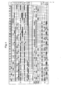
- Fig. 4 einen Schaltplan für den Schrittschalt-Programmgeber nach Fig. 3 mit Wechselkontakt-Schaltern,
- Fig. 5 eine schematische Darstellung der Wechselkontakt-Schalter zur Verwendung im Programmgeber für den Schaltplan nach Fig. 4, und
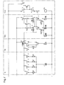
- Fig. 6 ein Schaltungsschema für eine Programmsteuerung nach der Erfindung für eine Waschmaschine.
- Gemäss Fig. 1 sind somit für die Steuerung einer Waschmaschine 10 mit einem Antriebsmotor 11 und beispielsweise drei Ventilen 12, 13, 14 als minimalste Anzahl Arbeitselemente neben beispielsweise einer Heizung zur Erwärmung des Wassers und Mitteln zur Veränderung der Motordrehzahl, ein Hauptbefehlsgeber 20, ein Datengeber 30 und verschiedene Drucktasten 40 vorhanden.
- Als Hauptbefehlsgeber 20 ist ein Lochkartenlesegerät 200 vorgesehen, das die Reihenfolge der einzelnen Programmschritte aus einer Streifen-Lochkarte entnehmen und an die Waschmaschine 10 und an den Datengeber 30 geben kann. Befehle, die vom Hauptbefehlsgeber 20 direkt über eine Befehlsleitung 21 an die Waschmaschine 10 abgegeben werden, sind beispielsweise die Schaltbefehle für Thermoschalter zum Erwärmen der Flotte auf eine bestimmte Temperatur. Die übrigen Befehle sind über die Datenleitung 22 zum Datengeber 30 geführt. Von den fünf dargestellten Schaltern wird beispielsweise mit dem Schalter 41 die Einschaltung des Hauptstromkreises bewirkt, mit dem Schalter 42 die Anschaltung des Datengebers 30, mit dem Schalter43 der Befehl zum Schleudern aus dem Hauptbefehlsgeber 20 mit dem Datengeber 30 in einen Befehl zum IntervallSchleudern umgewandelt, mit dem Schalter 44 der Wasserpegel abgesenkt und mit dem Schalter 45 wird eine Verbindung zwischen dem Datengeber 30 und dem Hauptbefehlsgeber 20 zur Veränderung der Laufgeschwindigkeit des Lochkartenlesegeräts zwecks Verkürzung der Programmdauer geschaffen.
- Als Datengeber 30 ist schliesslich ein Schrittschaltprogrammgeber 300 einer bekannten Bauart, beispielsweise ein Programmsteuergerät Typ 2HK4 der Firma Siemens AG, vorgesehen. Von diesem Programmsteuergerät können sämtliche Steuerbefehle für den Wasch- und Schleuderbetrieb ausgegeben werden, wie verschiedene Phasen des Zwischenschleuderns, verschiedene Stufen des Intervallschleuderns, des Endschleuderns und des Auflockerns der Wäsche, die immer sehr genau und während einer bestimmten Zeitdauer durchgeführt werden müssen.
- Zum besseren Verständnis der Erfindung werden nachfolgend ein Lochkartenlesegerät, eine Programmsteuerung durch den Datengeber und ein Schaltschema beschrieben.
- Das Lochkartenlesegerät 200 gemäss Fig. 2 als Hauptbefehlsgeber 20 in Fig. 1 ist auf einer Grundplatte 201 aufgebaut. Diese trägt die untere Führungsplatte 202 und die obere Führungsplatte 203 für die Führung einer Streifen-Lochkarte. Mit Schrauben 204, von denen nur eine ersichtlich ist, ist die obere Führungsplatte 203 auf der Grundplatte befestigt. Es sind insgesamt 16 Schalthebel 205 parallel nebeneinander und in Längsrichtung versetzt angeordnet. Diese Schalthebel 205 sind auf Schalthebelachsen 206, von denen nur eine ersichtlich ist, gehaltert. Ein Kamm 207 dient zur Parallelführung der Schalthebel 205. 16 Schalter 208 sind in Querrichtung und in Längsrichtung versetzt an vier Schalterachsen 210 befestigt. Die Leitungen zu den Schaltern 208 hin und von diesen weg sind auf eine Leiterplatte 211 geführt, wo auch die notwendigen internen Verknüpfungen angeordnet sind. Ein Synchro-Motor 214 dient zum Antrieb und Vorschub der Streifen-Lochkarte. Ueber das Motorritzel 215 wird ein Getriebe mit drei Zahnrädern 223a, 223b und 224 angetrieben, von denen ein Transportrad 220 mit Zähnen zum Eingriff in eine Randlochung der Streifen-Lochkarten angetrieben wird. Ein spezielles Bremsrad 221 bewirkt, dass das Transportrad 220 in die Randlochung der Lochkarte eingeschwenkt wird. Das Transportrad 220 wird durch ein Antriebsrad 225 angetrieben, das seinerseits starr mit dem Zahnrad 224 gekoppelt ist.
- Fig. 3 zeigt eine Ansicht auf die Antriebsseite eines Schrittschalters 300, der als Datengeber 30 in Fig. 1 eingesetzt sein kann. Der Schrittschalter besteht in üblichem Aufbau aus Antriebsteil mit Synchronmotor mit Dauermagnetrotor, Getriebe und Antriebsschwinge, ferner aus Steuer- und Zeitgeberwalze und dem Kontaktsatz.
- Der Motor Mum 1 (Fig. 6) treibt über das Antriebsritzel 301, ein Getriebe mit den Zahnrädern 302, 303 und 304 eine Schwinge 305 an, welche Schwinge an ihrem äusseren Ende den Transportstift 306 für die Weiterschaltung der Programmwalze 307 und der Zeitgeberwalze 308 trägt.
- Der Transportstift 306 arbeitet auf eine Verzahnung 310 der Zeitgeberwalze 308, um diese schrittweise anzutreiben. Wenn der Transportstift 306 auf einen Steuerschlitz trifft, greift er in die Verzahnung 311 der Programmwalze 307 ein und treibt diese mit der Zeitgeberwalze 308 zusammen um eine Position weiter. Da ein Steuerschlitz vorhanden ist, wird der Arbeitstakt der Pfogrammwalze 307 durch die Umlaufgeschwindigkeit der Zeitgeberwalze 308 bestimmt. In der vorgesehenen Ausführungsform sind gemäss Fig. 4 drei Transportstifte 306a, 306b und 306c vorhanden, wodurch unterschiedliche Schrittzeiten als Vielfache des Zeitgeberschrittes auf die Programmwalze 307 einwirken. Mit einem zusätzlichen Schnellgangmotor Mum 2 in Fig. 6 wird die Programmwalze 307 über ein Untersetzergetriebe mit Freilaufeinrichtung mit einer höheren Drehzahl angetrieben.
- In Fig. 5 sind die Schaltkontakte Ul-1 bis Ul-14 des Kontaktsatzes des Schrittschalters 300 mit dem beweglichen Schalteranschluss 1 und den beiden festen Schalteranschlüssen 2, 4 herausgezeichnet. Im Kontaktschema Fig. 4 ist der Schalteranschluss 4 jeweils in der oberen Hälfte des Feldes und der Schalteranschluss 2 in der unteren Hälfte des Feldes dargestellt.
- Es sind 10 Kontaktbahnen Ul mit der Programmwalze 307 und 4 Kontaktbahnen U2 mit der Zeitgeberwalze 308 vereinigt. In der Darstellung gemäss Fig. 4 sind zwischen der Programmwalze 307 und der Zeitgeberwalze 308 die Verzahnungen für die Transportstifte 306a, 306b und 306c dargestellt.
- Im Schaltungsschema Fig. 6 ist eine vollständige Steuerung für eine Waschmaschine dargestellt. Es lassen sich acht grundsätzliche Abschnitte unterscheiden:
- Der Abschnitt I beinhaltet die Schalter für Programm-Start-Stop. Im Abschnitt II sind die elektrischen Verbindungen für den Antrieb der Waschtrommel durch den Motor M bei Waschen im Reversierbetrieb, Schwingen und Auflockern dargestellt.
- Der Abschnitt III umfasst die interne Steuerung vom Lochkartenlesegerät 200 zum Schrittschalter 300 und der Abschnitt IV umfasst eine Anordnung für die Fehlschaltsicherheit. Im Abschnitt V ist die Programmsteuerung für die Temperaturwahl, z.B. 30, 40, 60 und 90°, untergebracht, während die Zyklussteuerung für Reversierbetrieb bei Schongang und Normalgang im Abschnitt VI liegt.
- Der Abschnitt VII umfasst die Steuerung für die Wasserzuleitung und die Einstellung des Pegels und schliesslich umfasst der Abschnitt VIII noch die zeitliche Steuerung des Lochkartenlesegerätes 200.
- Im einzelnen und ausführlicher beschrieben sind also ein Lochkartenlesegerät 200, ein Schrittschalter 300 und ein Drucktastengerät 40 vorhanden. Die Schalter 208 im Lochkartenlesegerät 200 sind im Schaltungsschema mit L1 bis L16 bezeichnet. Die Kontaktbahnen der Programmgeberwalze 307 tragen die Bezeichnung Ul und die der Zeitgeberwalze 308 die Bezeichnung U2. Die Drucktasten sind mit Dl - D5 angeschrieben.
- Die Netzspannung wird über die Anschlüsse R für die Phase und N für Nulleiter zugeführt. Wenn nun eine Lochkarte den Schalter Ll geschlossen hält, werden durch Drücken der Drucktaste D1 das Remanenz-Relais d2 sowie das Relais dl aufgezogen, und diese beiden Relais d1, d2 halten sich über die zugehörigen Kontakte dl, d2 solange als der Schalter L1 geschlossen ist. Ueber einen weiteren Kontakt des Relais d2 wird eine Signallampe hl angeschlossen und es gelangt Strom auf den Antrieb im Abschnitt II.
- Im Antriebssteuerteil, Abschnitt II, werden bei einem handelsüblichen Kollektormotor M mit drei bis vier verschiedenen Drehzahlen über Kontakte der Programmwalze 307 die verschiedenen Statorwicklungen zu- und abgeschaltet. Der Motor M läuft im Normalgang mit der Reversiersteuerung durch den Schalter U2-13 der Zeitsteuerwalze 308, wenn das Relais d5 im Abschnitt VI angezogen hat, das heisst, wenn der Niveauschalter SpN für das Sparniveau umgeschaltet hat und entweder der Kontakt U2-14 in Serie zum Schalter L3 liegt, oder die Schalter L3 und L4 in Serie zum bereits aufgezogenen Relais d5 geschlossen sind. Dann ist der Kontakt d5 im Abschnitt II geschlossen und mit dem Kontakt U2-13 der Zeitsteuerwalze 308 wird der Reversierbetrieb im Normalgang gesteuert. Mit den Schalterbahnen für die Kontakte Ul-2 und Ul-4 der Programmsteuerwalze 307 wird zwischen Auflockern/ Schleudern Stufe 1 und Schleudern Stufe 2/Endschleudern geschaltet. In Serie zum Anschluss 4 des Kontaktes Ul-4 liegt noch der Schaltkontakt U2-12 der Zeitsteuerwalze 308, der jeweils für Gleichlauf/Auflockern den Stromkreis zum Motor M schliesst.
- Die Wicklungen des Motors M sind in Serie zu einem Uebertemperaturschalter e2 am Nulleiter N nach einem Kontakt d3 des Relais für Verbraucherabtrennung angeschlossen. Der Antriebsmotor Muml für den Normalbetrieb des Schrittschalters 300 erfolgt mit der Parallelschaltung des Schalters L2 und der Drucktaste D2. Parallel zum Antriebsmotor Muml liegt auch die Steuerung für den Antriebsmotor 214 des Lochkartenlesegerätes 200 im Abschnitt VIII (Fig. 2). Mit dieser Parallelschaltung von Schalter L2 und Drucktaste D2 wird bewirkt, dass nach dem Spülen der Programmablauf angehalten werden kann.
- Im Abschnitt III liegt die Befehlsabgabe für das Programm "Zwischenschleudern", nämlich mit dem Kontakt Ul-1, das Programm "Endschleudern" mit dem Kontakt Ul-3, das Programm "Intervallschleudern" mit dem Kontakt Ul-5 und das Programm für "Programm-Unterbruch" des Lochkartenlesegerätes 200, beispielsweise während des Endschleuderns oder des 4. Intervallschleuderns.
- Der Programmbefehl "Zwischenschleudern" kann durch den Kontakt Ul-1 nur dann gegeben werden, wenn die seriegeschalteten Schalter L10, L14 nicht betätigt und der Schalter L12 betätigt ist. Der Programmbefehl "Intervallschleudern" kann durch den Kontakt Ul-5 nur bei gedrückter Drucktaste D3 entstehen.
- Wenn eine solche Schalterstrecke geschlossen ist, erhält der Schnellgangmotor Mum2 im Schrittschalter 300 Strom, aber nur während des Befehls "Zwischenschleudern" über die Schalter L10, L12, L14 und den Kontakt Ul-1.
- Mit der Fehlschaltsicherung im Abschnitt V zieht das Relais d4 bei erregtem Relais d2, wenn der Schalter L10 umgeschaltet hat, also keine Schleuderart vorgesehen ist und gleichzeitig der Kontakt Ul-10 für die Weiterführung der Programmwalze 307 im Schnellgang geschlossen ist. Solange das Relais d4 erregt ist, läuft der Motor Mum2.
- Ein Wasserpegelschalter SiN, der bei Erreichen des maximalen Niveaus durch den Wasserstand umgeschaltet wird, betätigt bei zu hohem Wasserstand den Ablaufpumpenmotor MAP. Im Normalfall wird dieser Motor MAP mit dem Schalter L10 betätigt. Gemäss der dargestellten Verdrahtung im Abschnitt V werden die einzelnen Temperaturüberwachungen mittels Thermostaten Th durch die Schalter L5-L8 angeschaltet und die Heizungen werden dementsprechend gespeist. Im anschliessenden Abschnitt VI wird in Abhängigkeit des Wasserniveaus bei Sparbetrieb mit dem Pegelschalter SpN das Relais d5, das einen Kontakt im Abschnitt II besitzt, erregt, und zwar hält sich das Relais d5, wenn mit dem Lochkartenlesegerät die beiden Schalter L3 und L4 geschlossen sind, über den Haltekontakt selbst, sobald der Kontakt U2-14 des Zeitgebers 308 einmal die Schaltstrecke 1 - 4 geschlossen hat. Bei offenem Schalter L4 wird mittels des Kontaktes U2-14 das Relais d5 periodisch betätigt, wodurch bei der einen Schalterstellung des Kontaktes U2-14 die Laufdauer des Antriebsmotors M doppelt so lange ist wie im andern Fall. Das Relais d5 fällt in den Zwischenzeiten ab und der Antriebsmotor M steht still.
- Die Ventile S1, S2, S3 im Abschnitt VII zum Auffüllen des benötigten Wasserstandes werden durch die Schalter L9, L15 und L16 nebst zwei Niveauschaltern NN, HN für Normalniveau bzw. Woll-/Spülniveau und einer Drucktaste D4 für Sparprogramm gesteuert.
- Schliesslich ist im Abschnitt VIII eine zeitliche Steuerung für den Motor 214 im Lochkartenlesegerät 200 enthalten. Im Normalbetrieb erhält der Motor 214 Strom über die in Reihe geschalteten Kontakte Ul-9 und U2-11 während des Zwischenschleuderns und während des Endschleuderns und Auflockerns, und zwar impulsweise während 2/3 der Laufzeit der Zeitgeberwalze 308. Wenn dagegen mit der Drucktaste D5 das Kurzprogramm gewählt wird, so erhält der Motor 214 den Speisestrom nach Massgabe des Schalters Lll und während den oben genannten Schleuderphasen kontinuierlich mittels des Kontaktes Ul-9 der Programmwalze 307.
- Durch diese Kombination von Lochkartensteuerung 200 und Zeitsteuerung mit einer schrittgeschalteten Programmwalze 307 müssen die Steuerausnehmungen in den Lochkarten nicht mehr mit den bisher benötigten kleinen Toleranzen gefertigt werden und es genügt, wenn die Lochkarte die wesentlichen Programmschritte einleitet. Die Durchführung der Abläufe während der einzelnen Programmschritte übernimmt die Programmwalze 307 mit äusserster Präzision, weil bei einem Umlauf der Zeitgeberwalze 308, der beispielsweise 175 s dauern kann, für jeden einzelnen Schritt 3,65 s zur Verfügung stehen.
- Die Abläufe der Programmwalze 307 des Schrittschalters 300 stellen somit Unterprogramme dar, die durch das Lochkartenlesegerät 200 abgerufen werden können. Vor und nach Ablauf eines ausgewählten Unterprogramms synchronisieren sich die beiden Steuergeräte selbsttätig und das Lochkartenlesegerät 200 steuert den Waschprozess wieder allein. Es ist somit möglich, jederzeit genaue Programmzyklen aus dem Schrittschalter 300 mit starrer Programmierung abzurufen und zu einem geordneten Waschprogramm zusammenzustellen. Durch die Schaltungsanordnung im Abschnitt IV ist die Fehlschaltsicherheit beim Verschieben der Lochkarte im Lochkartenlesegerät 200 gewährleistet.
- Obwohl die Befehlsgabe grundsätzlich vom Lochkartenlesegerät 200 zum Schrittschalter 300 erfolgt, wodurch ein Befehlsgeber-Befehlsempfänger-Verhältnis festgelegt ist, kann der Schrittschalter 300 mittels der Kontaktbahn U2-11 die Vorschubgeschwindigkeit verlangsamen. Für die Zuordnung der verschiedenen Vorschubgeschwindigkeiten ist jedoch das Lochkartenlesegerät 200 ebenfalls bestimmend.
- Die zusätzlichen fünf Drucktasten Dl bis D5 gestatten einen weiteren Eingriff in ein bestehendes Programm. So kann mit der Drucktaste D2 bei normalem Waschprogramm der Befehl "Stop nach Spülen" eingegeben werden, wodurch das Schleudern entfällt. Die Drucktaste D3 führt zusammen mit der Kontaktbahn Ul-5 der Programmwalze 307 ein zusätzliches Programm "Intervallschleudern" ein.
- Dabei werden die folgenden Schritte durch die Programmwalze 307 des Schrittschalters 300 bewirkt:
- 1. das Lochkartenlesegerät 200 wird auf den Startzeitpunkt des Schrittschalters 300 synchronisiert;
- 2. der Gleichlauf wird bei Waschdrehzahl des Antriebsmotors M durch den Kontakt Ul-4 bewirkt, indem die Anschlüsse 1 - 4 überbrückt sind;
- 3. der Antriebsmotor M wird während der Zeit, in der der Kontakt Ul-4 die Anschlüsse überbrückt, auf die erste Schleuderstufe beschleunigt;
- 4. der Antriebsmotor M wird durch den Kontakt Ul-2 auf die zweite Schleuderdrehzahl beschleunigt;
- 5. die beiden Anschlüsse 1-2 der Kontaktbahn Ul-4 und 1-2 der Kontaktbahn Ul-2 werden geöffnet und der Antriebsmotor M ist damit stromlos und die Trommel wird durch Reibung abgebremst;
- 6. als letztes schaltet der Kontakt Ul-4 und verbindet die Anschlüsse 1 - 4, wodurch eine Auflockerungsdrehzahl bewirkt wird.
- Dieser Ablauf wird viermal wiederholt.
- Die Drucktaste D4 bewirkt ein "Sparprogramm", d.h. es wird weniger Wasser benötigt als für das Normalprogramm. In den Abschnitten VI und - VII wird bei Erreichen des Sparniveaus, d.h. wenn der Pegelschalter SpN schaltet, die Wasserzufuhr gestoppt. Mit dem Schalter L3 wird zwischen den beiden Betriebsarten der Kontaktbahn U2-14 gewählt, wodurch die Trommel entweder während 1/3 oder 2/3 einer Zeitperiode von 3 x 3,65 s rotiert wird. Wenn durch den Lochkartenleser 300 jedoch der Schalter L4 geschlossen wird, so arbeitet der Antriebsmotor M gemäss dem Waschtakt der Zeitgeberwalze 308 in der Kontaktbahn U2-13.
- Durch Wahl des "Kurzprogramms" mit der Drucktaste D5 wird im Lochkartenlesegerät der Motor 214 nicht durch die Kontaktbahn U2-11 während 2/3 der Zeit angeschaltet, sondern er bleibt infolge der Steuerung durch den Schalter Lll und durch die Kontaktbahn Ul-9 in den Schleuderphasen dauernd angeschaltet.
- Durch diese verschiedenen individuell wählbaren Befehle kann ein Programm stark verkürzt oder verlängert werden.
Claims (10)
Priority Applications (1)
| Application Number | Priority Date | Filing Date | Title |
|---|---|---|---|
| AT83810155T ATE28529T1 (de) | 1982-04-16 | 1983-04-15 | Schaltungsanordnung zur programmsteuerung einer maschine. |
Applications Claiming Priority (2)
| Application Number | Priority Date | Filing Date | Title |
|---|---|---|---|
| CH233782 | 1982-04-16 | ||
| CH2337/82 | 1982-04-16 |
Publications (2)
| Publication Number | Publication Date |
|---|---|
| EP0092523A1 true EP0092523A1 (de) | 1983-10-26 |
| EP0092523B1 EP0092523B1 (de) | 1987-07-22 |
Family
ID=4231456
Family Applications (1)
| Application Number | Title | Priority Date | Filing Date |
|---|---|---|---|
| EP83810155A Expired EP0092523B1 (de) | 1982-04-16 | 1983-04-15 | Schaltungsanordnung zur Programmsteuerung einer Maschine |
Country Status (3)
| Country | Link |
|---|---|
| EP (1) | EP0092523B1 (de) |
| AT (1) | ATE28529T1 (de) |
| DE (1) | DE3372676D1 (de) |
Citations (6)
| Publication number | Priority date | Publication date | Assignee | Title |
|---|---|---|---|---|
| GB1086120A (en) * | 1964-06-09 | 1967-10-04 | Siemens Ag | Pushbutton unit having a variable switching programme |
| DE1610208A1 (de) * | 1964-06-03 | 1970-02-19 | Scharpf Geb Kg | Steuereinrichtung fuer Waschmaschinen |
| FR2098065A5 (de) * | 1970-07-16 | 1972-03-03 | Siemens Elektrogeraete Gmbh | |
| US4084237A (en) * | 1977-03-28 | 1978-04-11 | Economics Laboratory, Inc. | Electronic laundry program control apparatus |
| US4195232A (en) * | 1978-01-26 | 1980-03-25 | Whirlpool Corporation | Selection acknowledgement system for a laundry appliance |
| EP0046483A2 (de) * | 1980-08-13 | 1982-03-03 | Bosch-Siemens HausgerÀ¤te GmbH | Elektronischer Programmwahlschalter |
-
1983
- 1983-04-15 AT AT83810155T patent/ATE28529T1/de not_active IP Right Cessation
- 1983-04-15 EP EP83810155A patent/EP0092523B1/de not_active Expired
- 1983-04-15 DE DE8383810155T patent/DE3372676D1/de not_active Expired
Patent Citations (6)
| Publication number | Priority date | Publication date | Assignee | Title |
|---|---|---|---|---|
| DE1610208A1 (de) * | 1964-06-03 | 1970-02-19 | Scharpf Geb Kg | Steuereinrichtung fuer Waschmaschinen |
| GB1086120A (en) * | 1964-06-09 | 1967-10-04 | Siemens Ag | Pushbutton unit having a variable switching programme |
| FR2098065A5 (de) * | 1970-07-16 | 1972-03-03 | Siemens Elektrogeraete Gmbh | |
| US4084237A (en) * | 1977-03-28 | 1978-04-11 | Economics Laboratory, Inc. | Electronic laundry program control apparatus |
| US4195232A (en) * | 1978-01-26 | 1980-03-25 | Whirlpool Corporation | Selection acknowledgement system for a laundry appliance |
| EP0046483A2 (de) * | 1980-08-13 | 1982-03-03 | Bosch-Siemens HausgerÀ¤te GmbH | Elektronischer Programmwahlschalter |
Also Published As
| Publication number | Publication date |
|---|---|
| DE3372676D1 (en) | 1987-08-27 |
| ATE28529T1 (de) | 1987-08-15 |
| EP0092523B1 (de) | 1987-07-22 |
Similar Documents
| Publication | Publication Date | Title |
|---|---|---|
| DE2041040C3 (de) | Steuerungseinrichtung für eine durch einen Motor antreibbare umlaufende Lagervorrichtung | |
| DE886621C (de) | Automatische, elektrisch betriebene Waschmaschine | |
| EP0092523B1 (de) | Schaltungsanordnung zur Programmsteuerung einer Maschine | |
| DE1463229C3 (de) | Von Hand voreinstellbare Programm-Steuervorrichtung für Werkzeugmaschinen | |
| DE69202684T2 (de) | Waschmaschinen- oder Trocknerprogrammschaltwerk mit zwei verschiedenartigen Zeitbasen. | |
| DE3003847C2 (de) | ||
| DE3300200C2 (de) | Programmschalter für Waschmaschinen | |
| AT201019B (de) | Steuerung für automatische Waschmaschinen | |
| DE3686005T2 (de) | Programmiergeraet fuer eine waschmaschine. | |
| DE2716240A1 (de) | Elektrisches programmsteuergeraet | |
| DE2214514C3 (de) | Anordnung zur Programmsteuerung von Waschmaschinen | |
| DE1460993A1 (de) | Elektrisches Programmsteuergeraet,vorzugsweise fuer elektrische Haushaltsgeraete,insbesondere Waschmaschinen und Geschirrspuelmaschinen | |
| DE2438430C2 (de) | Anordnung zur Programmsteuerung für Waschmaschinen | |
| DE737724C (de) | Steuerung fuer vollelektrisch geschaltete Fraesmaschine, insbesondere Konsolfraesmaschine | |
| DE1538437C3 (de) | Programmauswahleinrichtung für ein motorgetriebenes Programmsteuergerät | |
| DE1485046C (de) | Programmsteuereinrichtung fur einen mit einem Munzkassierwerk ver sehenen Waschautomaten | |
| DE2612852C2 (de) | ||
| CH350951A (de) | Programmgeber für automatische Waschmaschinen | |
| AT232945B (de) | Programmsteuerung für Waschmaschinen | |
| DE1485003B2 (de) | Programmschalteinrichtung fuer waschautomaten | |
| GB1106657A (en) | Improvements in programme control devices, particularly for the control of automatic washing machines | |
| DE887277C (de) | Einrichtung zur selbsttaetigen Steuerung von Belastungsversuchen | |
| AT266748B (de) | Steuerwerk für mehrere Programme für Waschmaschinen | |
| DE1760763A1 (de) | Elektrisches Programmsteuergeraet | |
| EP0046483A2 (de) | Elektronischer Programmwahlschalter |
Legal Events
| Date | Code | Title | Description |
|---|---|---|---|
| PUAI | Public reference made under article 153(3) epc to a published international application that has entered the european phase |
Free format text: ORIGINAL CODE: 0009012 |
|
| AK | Designated contracting states |
Designated state(s): AT BE CH DE FR GB IT LI LU NL |
|
| 17P | Request for examination filed |
Effective date: 19840227 |
|
| ITF | It: translation for a ep patent filed | ||
| GRAA | (expected) grant |
Free format text: ORIGINAL CODE: 0009210 |
|
| AK | Designated contracting states |
Kind code of ref document: B1 Designated state(s): AT BE CH DE FR GB IT LI LU NL |
|
| REF | Corresponds to: |
Ref document number: 28529 Country of ref document: AT Date of ref document: 19870815 Kind code of ref document: T |
|
| REF | Corresponds to: |
Ref document number: 3372676 Country of ref document: DE Date of ref document: 19870827 |
|
| ET | Fr: translation filed | ||
| PLBE | No opposition filed within time limit |
Free format text: ORIGINAL CODE: 0009261 |
|
| STAA | Information on the status of an ep patent application or granted ep patent |
Free format text: STATUS: NO OPPOSITION FILED WITHIN TIME LIMIT |
|
| 26N | No opposition filed | ||
| PGFP | Annual fee paid to national office [announced via postgrant information from national office to epo] |
Ref country code: FR Payment date: 19920309 Year of fee payment: 10 |
|
| PGFP | Annual fee paid to national office [announced via postgrant information from national office to epo] |
Ref country code: AT Payment date: 19920310 Year of fee payment: 10 |
|
| PGFP | Annual fee paid to national office [announced via postgrant information from national office to epo] |
Ref country code: GB Payment date: 19920312 Year of fee payment: 10 Ref country code: CH Payment date: 19920312 Year of fee payment: 10 |
|
| PGFP | Annual fee paid to national office [announced via postgrant information from national office to epo] |
Ref country code: DE Payment date: 19920318 Year of fee payment: 10 |
|
| PGFP | Annual fee paid to national office [announced via postgrant information from national office to epo] |
Ref country code: LU Payment date: 19920324 Year of fee payment: 10 |
|
| PGFP | Annual fee paid to national office [announced via postgrant information from national office to epo] |
Ref country code: BE Payment date: 19920330 Year of fee payment: 10 |
|
| ITTA | It: last paid annual fee | ||
| PGFP | Annual fee paid to national office [announced via postgrant information from national office to epo] |
Ref country code: NL Payment date: 19920430 Year of fee payment: 10 |
|
| EPTA | Lu: last paid annual fee | ||
| PG25 | Lapsed in a contracting state [announced via postgrant information from national office to epo] |
Ref country code: LU Free format text: LAPSE BECAUSE OF NON-PAYMENT OF DUE FEES Effective date: 19930415 Ref country code: GB Effective date: 19930415 Ref country code: AT Effective date: 19930415 |
|
| PG25 | Lapsed in a contracting state [announced via postgrant information from national office to epo] |
Ref country code: LI Effective date: 19930430 Ref country code: CH Effective date: 19930430 Ref country code: BE Effective date: 19930430 |
|
| BERE | Be: lapsed |
Owner name: MASCHINENFABRIK AD. SCHULTHESS & CO.A.G. Effective date: 19930430 |
|
| PG25 | Lapsed in a contracting state [announced via postgrant information from national office to epo] |
Ref country code: NL Effective date: 19931101 |
|
| GBPC | Gb: european patent ceased through non-payment of renewal fee |
Effective date: 19930415 |
|
| NLV4 | Nl: lapsed or anulled due to non-payment of the annual fee | ||
| PG25 | Lapsed in a contracting state [announced via postgrant information from national office to epo] |
Ref country code: FR Effective date: 19931229 |
|
| REG | Reference to a national code |
Ref country code: CH Ref legal event code: PL |
|
| PG25 | Lapsed in a contracting state [announced via postgrant information from national office to epo] |
Ref country code: DE Effective date: 19940101 |
|
| REG | Reference to a national code |
Ref country code: FR Ref legal event code: ST |