EP0092593A1 - Procédé et appareillage pour la fabrication de lés en papier pouvant être coupés en bandes servant de couvre chant pour pannaux en bois - Google Patents
Procédé et appareillage pour la fabrication de lés en papier pouvant être coupés en bandes servant de couvre chant pour pannaux en bois Download PDFInfo
- Publication number
- EP0092593A1 EP0092593A1 EP82103472A EP82103472A EP0092593A1 EP 0092593 A1 EP0092593 A1 EP 0092593A1 EP 82103472 A EP82103472 A EP 82103472A EP 82103472 A EP82103472 A EP 82103472A EP 0092593 A1 EP0092593 A1 EP 0092593A1
- Authority
- EP
- European Patent Office
- Prior art keywords
- paper web
- paint
- paper
- wood
- printing
- Prior art date
- Legal status (The legal status is an assumption and is not a legal conclusion. Google has not performed a legal analysis and makes no representation as to the accuracy of the status listed.)
- Granted
Links
- 238000000034 method Methods 0.000 title claims abstract description 31
- 238000004519 manufacturing process Methods 0.000 title claims description 5
- 239000002023 wood Substances 0.000 claims abstract description 27
- 229920000877 Melamine resin Polymers 0.000 claims abstract description 16
- 239000004640 Melamine resin Substances 0.000 claims abstract description 16
- 229920003180 amino resin Polymers 0.000 claims abstract description 7
- 238000007646 gravure printing Methods 0.000 claims abstract description 6
- 239000003973 paint Substances 0.000 claims description 37
- 238000007639 printing Methods 0.000 claims description 26
- 238000000576 coating method Methods 0.000 claims description 21
- 239000011248 coating agent Substances 0.000 claims description 19
- 238000004049 embossing Methods 0.000 claims description 14
- 238000007591 painting process Methods 0.000 claims description 8
- 238000010073 coating (rubber) Methods 0.000 claims description 7
- 238000004026 adhesive bonding Methods 0.000 claims description 5
- 238000010422 painting Methods 0.000 claims description 5
- 230000001680 brushing effect Effects 0.000 claims description 2
- 239000012858 resilient material Substances 0.000 claims description 2
- 238000004804 winding Methods 0.000 claims description 2
- 239000004922 lacquer Substances 0.000 description 18
- 238000005470 impregnation Methods 0.000 description 4
- 239000000047 product Substances 0.000 description 4
- 238000003860 storage Methods 0.000 description 4
- 239000000428 dust Substances 0.000 description 3
- 229910000831 Steel Inorganic materials 0.000 description 2
- 239000007795 chemical reaction product Substances 0.000 description 2
- 239000011148 porous material Substances 0.000 description 2
- 238000002791 soaking Methods 0.000 description 2
- 239000010959 steel Substances 0.000 description 2
- 238000007664 blowing Methods 0.000 description 1
- 239000003086 colorant Substances 0.000 description 1
- 238000004040 coloring Methods 0.000 description 1
- 238000010276 construction Methods 0.000 description 1
- 230000000694 effects Effects 0.000 description 1
- 238000007654 immersion Methods 0.000 description 1
- 238000003754 machining Methods 0.000 description 1
- 239000006247 magnetic powder Substances 0.000 description 1
- 238000012423 maintenance Methods 0.000 description 1
- 230000007257 malfunction Effects 0.000 description 1
Images


Classifications
-
- B—PERFORMING OPERATIONS; TRANSPORTING
- B41—PRINTING; LINING MACHINES; TYPEWRITERS; STAMPS
- B41F—PRINTING MACHINES OR PRESSES
- B41F9/00—Rotary intaglio printing presses
-
- B—PERFORMING OPERATIONS; TRANSPORTING
- B41—PRINTING; LINING MACHINES; TYPEWRITERS; STAMPS
- B41F—PRINTING MACHINES OR PRESSES
- B41F23/00—Devices for treating the surfaces of sheets, webs, or other articles in connection with printing
-
- B—PERFORMING OPERATIONS; TRANSPORTING
- B41—PRINTING; LINING MACHINES; TYPEWRITERS; STAMPS
- B41M—PRINTING, DUPLICATING, MARKING, OR COPYING PROCESSES; COLOUR PRINTING
- B41M3/00—Printing processes to produce particular kinds of printed work, e.g. patterns
- B41M3/06—Veined printings; Fluorescent printings; Stereoscopic images; Imitated patterns, e.g. tissues, textiles
-
- B—PERFORMING OPERATIONS; TRANSPORTING
- B44—DECORATIVE ARTS
- B44C—PRODUCING DECORATIVE EFFECTS; MOSAICS; TARSIA WORK; PAPERHANGING
- B44C5/00—Processes for producing special ornamental bodies
- B44C5/04—Ornamental plaques, e.g. decorative panels, decorative veneers
- B44C5/0469—Ornamental plaques, e.g. decorative panels, decorative veneers comprising a decorative sheet and a core formed by one or more resin impregnated sheets of paper
Definitions
- the invention relates to a method and an apparatus for the production of paper webs to be longitudinally divided into several strips for gluing the edges of boards made of wood, in particular furniture, in which an optionally colored paper web is printed with a wood color and wood structure, impregnated with an aminoplast, in particular melamine resin, lacquered and is shaped. Then the track is divided lengthways.
- the known method is carried out in such a way that the optionally colored paper web on a roll is unwound and printed and rewound in a printing machine, which usually consists of several printing units, with the wood color and the wood structure pattern.
- a printing machine usually consists of several printing units, with the wood color and the wood structure pattern.
- the impregnation of the paper webs with melamine resin, the painting and the embossing are separate work processes for the implementation of which the web is in turn wound up and unwound.
- the narrow strips are then produced by slitting the webs lengthways. This procedure is open due to the numerous handling processes visibly uneconomical and it would be desirable if one could carry out all processing operations in one pass.
- the throughput speed in all processing operations would have to depend on the throughput speed of the processing operation that requires the lowest throughput speed, and in this case this is the impregnation of the webs with melamine resin.
- throughput speeds of 2o to a maximum of 4o meters per minute can be used, while printing, on the other hand, speeds of 8o to 200 meters per minute. Under these circumstances, performing all machining operations in one pass would result in an even less economical result.
- the object of the invention is to be able to produce the paper webs to be cut only by slitting into narrow strips from a preliminary product in only one pass, even in small quantities.
- the invention relates to a method for producing paper webs to be longitudinally divided into several strips for gluing the edges of boards made from wood, in particular furniture, in which an optionally colored paper web is colored with a wood color and a wood Structure printed with an aminoplast, in particular melamine resin, is impregnated, varnished and embossed and which is characterized in that the optionally colored paper and impregnated with an aminoplast, in particular melamine resin, is printed in a subsequent operation with a wood color and a wood structure, then varnished and finally embossed becomes.
- the throughput speed in the method according to the invention is high, since it is no longer limited by the low throughput speed required for soaking with melamine resin. Since the end product can be produced quickly and economically in almost any small batch sizes, storage of the end product can be almost completely eliminated and storage can be limited to the preliminary product.
- the paper web is subjected to several successive printing processes and is dried by warm air after each printing process. This will make a high Throughput speed enables and at the same time a small overall length of the device used to carry out the method.
- the paper web can be subjected to several successive painting processes and the paint is cured by infrared rays after each painting process, the heat applied to the paper web increasing with increasing distance from the point at which the paint is applied.
- the paint is cured quickly and gently, damage to the paper is avoided, and high throughput speeds and a short overall length of the device are made possible.
- Another object of the invention is a device used to carry out the above-identified method, which in turn is characterized by an unwinder, one or more indirect gravure printing units, one or more coating units, an embossing unit and a winding device.
- the device according to the invention allows the primary product printed with a base color and soaked in melamine resin to be processed in one pass to the finished paper web then only has to be divided lengthways.
- the unwinding device is followed by a clamping device for the paper web.
- This clamping device serves to hold the end of the previous paper web when changing the roll so that it can be glued to the beginning of the following paper web, so that the device is traversed by an endless paper web.
- a brushing device provided with rotating brushes in front of the first printing unit, by means of which dust that may be on the surfaces of the paper web is removed and thus a clean print is ensured.
- a Shore hardness A of about 50 ° is expediently chosen for the rubber coating of the transfer roller and a Shore hardness A of about 85 for the rubber coating of the counterpressure roller.
- the blade in the printing units so that they are pivotable about their longitudinal axes by more than 9 0 °. This facilitates the often required removal of the ink roller.
- the inking units of the printing units can have ink troughs which are provided with an ink supply connected to an ink pump and a color return determining the level. As a result, the color level in the color troughs is obtained in a very simple manner kept constant.
- the coating units are expediently designed such that they have coating pick-up rollers arranged in coating trays, which are provided with a rough, in particular rastered surface and which interact with coating transfer rollers arranged above them, while counter-pressure rollers are arranged above the coating transfer rollers and above the paper web. This results in an extremely uniform application of lacquer to the paper, the thickness of which can be influenced by the surface shape of the lacquer pick-up roller.
- the paint troughs arranged in the coating units have paint inlets arranged at a level-determining height, which are connected via lacquer supply lines provided with shut-off devices to airtightly closable paint containers arranged above the paint troughs.
- the paint level in the paint troughs can be determined in the simplest way and the contact of the paint with the air is limited to a minimum.
- the embossing unit has an engraved embossing roller and a counterpressure roller which is made of non-resilient material and has a flat surface.
- a counterpressure roller which is made of non-resilient material and has a flat surface.
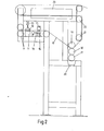
- the unwinding device shown in FIG. 1 and designated in its entirety by 1 consists of a base frame 2 on which two levers 3 of equal arm running parallel to one another are arranged so as to be pivotable about a pivot point 4.
- the levers 3 have tension at their ends devices 5, 6 for receiving paper rolls 7.
- the paper is a paper impregnated with an aminoplast, in particular with melamine resin and possibly colored. The coloring of the paper is necessary if the paper is printed with a relatively dark wood color. Otherwise the cut edges of the paper would appear light colored.
- the tensioning device 6 picks up a further paper roll, the beginning of which is laid ready and connected at the appropriate time to the end of the paper web of the roll 7.
- the first printing unit shown in FIG. 2, designated in its entirety by 8, has on its paper inlet side first behind guide rollers 9 a fixed clamping bar 11 arranged below the paper web 10, which is opposite a movable clamping bar 12 above the paper web 10, which with the help of one or more Compressed air cylinder 13 can be pressed against the fixed clamping bar 11, whereby the paper web 1o is held.
- a fixed clamping bar 11 arranged below the paper web 10
- a movable clamping bar 12 above the paper web 10 which with the help of one or more Compressed air cylinder 13 can be pressed against the fixed clamping bar 11, whereby the paper web 1o is held.
- the clamping device 11, 12, 13 is followed in the running direction of the paper web 1o by a pair of rotating brushes 14 and 15, between which the paper web 1o runs and which can be pressed against one another by a pneumatic adjusting device 16.
- the brushes are used to remove dust and foreign bodies from the surfaces of the paper web, as these can impair the printed image and lead to malfunctions.
- q device for the dust formed In the area of the brushes a Absau not shown in the drawing, q device for the dust formed arranged.
- the actual printing unit consists of the gravure engraving roller 17, the transfer roller 18 arranged above it and the counter-pressure roller or impression roller 19 arranged above it.
- the transfer roller 18 and the counter-pressure roller 19 have rubber coatings.
- the rubber coating of the transfer roller has a Shore hardness .A of about 5o
- the rubber coating of the counterpressure roller has a Shore hardness A of about 85.
- the ink fountain marked 2o can be lowered from its operating position shown in the drawing and the one not shown in the drawing with the gravure printing.
- Engraving roller 17 cooperating doctor blade is pivotable from its operating position about its longitudinal axis, which runs parallel to the roller 17, by at least 90 °. In this way, the roller 17 can be easily and freely removed for the purpose of changing.
- the gravure engraving roller 17 picks up ink from the ink trough 2o in its depressions, the excess on the roller becomes the stripped by the doctor blade, not shown in the drawing.
- the paint located in their recesses are the roller 17 to the rubber coating of the transfer roller 18, and from there reaches the color on the underside of the paper web 1 is 0, which is pressed by the platen roller 19 against the transfer roller 18th
- an excellent wood structure print can be produced on the paper web 10, which is stiff due to the melamine resin impregnation and is otherwise difficult to print.
- the still moist paper web 10 is deflected by two further guide and deflection rollers 21, 22 and reaches an air box 23 in which the ink is dried by blowing with warm air.
- the ink supply to the ink pan 20 is shown in detail.
- 24 denotes an approximately bucket-shaped ink reservoir into which an immersion pump 25 is inserted.
- the submersible pump 25 conveys paint into the paint trough 20 via a line 26.
- a return line 27 is also arranged on the ink trough 20, through which excess ink runs back into the ink tank 24.
- the point of confluence of the return line 27 in the paint pan 2o determines the color level prevailing in the paint pan.
- At the bottom of the ink tray 28 is disposed ückflußtechnisch 2o is another R, which opens into the first return line 27, but d'ie by a valve 29 is shut off. This second return line 28 is used when the valve 29 is opened to completely empty the ink pan 2 0 .
- the delivery rate of the submersible pump 25 is adjusted so that more ink is always delivered than is consumed, so that a constant backflow takes place through the backflow line 27.
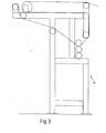
- the second printing unit shown in FIG. 3, denoted in its entirety by 3o, is basically of the same construction as the printing unit 8 and therefore need not be described in more detail. However, it lacks the terminal apparatus 1 0, 11, 12, 13 and the rotating brushes 14, 15, 16 with screwdown In general, be in a device according to the invention three or more printing units of the type described above. In the first of the printing units mentioned above, an engraving roller which has a wooden structure will generally not be present, since there the paper is printed over the entire surface with a wooden color or basic color.
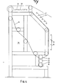
- the coating unit shown in FIG. 4 is designated in its entirety by 31.
- the coating unit 31 has a coating pan 32 into which a coating roller 33 is immersed.
- the lacquer roller 33 has a rough, preferably engraved or rastered surface, the roughness of which is dimensioned such that it takes the desired quantity of lacquer from the lacquer pan 32.
- the paint is delivered from the paint roller 33 to a transfer roller 34 and from this to the underside of the paper web 10.
- a counter pressure roller 35 presses the paper web 1o against the transfer roller 34.
- the rollers 34 and 35 are covered with rubber and correspond to the rollers 18 and 19 of the printing units.
- radiators are combined to radiator sets 36, 37, 38.
- the emitter set 36 which is first reached by the wet paper web 10 contains relatively few emitters 39, so that the heat applied to the paper web is comparatively low.
- the subsequent beam lerA 37 and 38 are each more radiators 39 arranged so that the heat load of the paper web is greater in these areas.
- the thermal load on the paper web can also be influenced by its distance from the paper web. The emitters emit a short-wave infrared light.
- a paint reservoir is designated, which can be closed airtight with the help of a lid 41.
- a line 42 leads from the lacquer storage vessel 4o to the lacquer pan 32.
- the line 42 can be shut off with a shut-off valve 43.
- the shut-off valve 43 is closed and the paint reservoir 4o is filled.
- the shut-off valve 43 is opened and so much lacquer closes into the lacquer pan 32 until the lacquer level 45 has reached the upper edge 44 of the junction of the line 42 into the lacquer pan 32. If paint is removed from the paint tub 32 by the roller 33, a corresponding amount of paint flows into the tub 32 through the line 42.
- this arrangement has the advantage that the paint comes into contact with air as little as possible.
- the process is carried out in such a way that, with the help of the first coating unit, initially only a relatively thin one Lacquer layer is applied to the paper web 10 and is cured on it. This thin layer of lacquer closes the surface pores of the paper.
- a thicker layer of lacquer is applied to the paper web treated in this way, which, however, cannot now penetrate the paper, but is cured on the first lacquer layer.
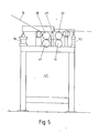
- the embossing unit 46 shown in FIG. 5 is designated 46 in its entirety. It contains an engraved embossing roller 41 made of steel and a counter-pressure roller 48 also made of steel with a smooth surface. The rolls are pressed against each other by a pneumatic cylinder 50 and the height of the roll gap remaining between them is set by a stop 49. In the roll gap passing through the paper web 10, the paper is compressed at those points at which the engraved embossing roller has 47 elevations. Furthermore, two guin-covered rollers 51 and 52 are provided, which can also be pressed against each other by a pneumatic cylinder 53. These rollers serve to pull the paper web 1o through the device when the rollers 47 and 48 have moved so far apart that they do not grip the paper web. In this case, the rollers. 51 and 52 driven. In embossing operation, the rollers 51 and 52 are without drive and the rollers 47 and 48 are driven.
- the take-up station shown in FIG. 6, designated 51 in its entirety, corresponds essentially to the take-off device 1 shown in FIG. 1 , but with the difference that its tensioning device lines 53 and 54 are driven to wind the paper web lo.
Landscapes
- Engineering & Computer Science (AREA)
- Mechanical Engineering (AREA)
- Health & Medical Sciences (AREA)
- General Health & Medical Sciences (AREA)
- Textile Engineering (AREA)
- Vascular Medicine (AREA)
- Paper (AREA)
- Laminated Bodies (AREA)
Priority Applications (2)
| Application Number | Priority Date | Filing Date | Title |
|---|---|---|---|
| EP19820103472 EP0092593B1 (fr) | 1982-04-24 | 1982-04-24 | Procédé et appareillage pour la fabrication de lés en papier pouvant être coupés en bandes servant de couvre chant pour pannaux en bois |
| DE8282103472T DE3278973D1 (en) | 1982-04-24 | 1982-04-24 | Process and apparatus for the production of paper webs which may be cut into ribbons for use as veneers for wooden panel edges |
Applications Claiming Priority (1)
| Application Number | Priority Date | Filing Date | Title |
|---|---|---|---|
| EP19820103472 EP0092593B1 (fr) | 1982-04-24 | 1982-04-24 | Procédé et appareillage pour la fabrication de lés en papier pouvant être coupés en bandes servant de couvre chant pour pannaux en bois |
Publications (2)
| Publication Number | Publication Date |
|---|---|
| EP0092593A1 true EP0092593A1 (fr) | 1983-11-02 |
| EP0092593B1 EP0092593B1 (fr) | 1988-08-31 |
Family
ID=8189004
Family Applications (1)
| Application Number | Title | Priority Date | Filing Date |
|---|---|---|---|
| EP19820103472 Expired EP0092593B1 (fr) | 1982-04-24 | 1982-04-24 | Procédé et appareillage pour la fabrication de lés en papier pouvant être coupés en bandes servant de couvre chant pour pannaux en bois |
Country Status (2)
| Country | Link |
|---|---|
| EP (1) | EP0092593B1 (fr) |
| DE (1) | DE3278973D1 (fr) |
Cited By (9)
| Publication number | Priority date | Publication date | Assignee | Title |
|---|---|---|---|---|
| FR2626813A1 (fr) * | 1988-02-04 | 1989-08-11 | Polygraph Leipzig | Machine a imprimer avec transport d'epreuves avec transfert complet des epreuves |
| FR2665117A1 (fr) * | 1990-07-25 | 1992-01-31 | Rossetto Arredamenti Spa | Procede de fabrication de revetements decoratifs pour meubles de decoration. |
| EP1473091A1 (fr) * | 2003-04-30 | 2004-11-03 | TRW Automotive Safety Systems GmbH | Elément de construction en bois artificiel et son procédé de fabrication |
| BE1017928A3 (nl) * | 2008-01-09 | 2009-11-03 | Flooring Ind Ltd Sarl | Vloerbekleding gevormd uit vloerpanelen, werkwijze voor het vervaardigen van deze vloerpanelen. |
| WO2009087440A3 (fr) * | 2008-01-09 | 2010-01-28 | Flooring Industries Limited, Sarl | Revêtement de sol, formé à partir de panneaux de plancher et procédé de fabrication desdits panneaux de plancher |
| BE1018213A3 (nl) * | 2008-07-14 | 2010-07-06 | Flooring Ind Ltd Sarl | Werkwijze voor het vervaardigen van beklede panelen en bekleed paneel hierbij verkregen. |
| WO2010084386A3 (fr) * | 2009-01-20 | 2010-09-30 | Flooring Industries Limited, Sarl | Procédés de fabrication de panneaux et panneau ainsi obtenu |
| US9114603B2 (en) | 2007-03-28 | 2015-08-25 | Pergo (Europe) Ab | Process for color variability in printing to simulate color variation of natural product |
| DE102008064923B3 (de) * | 2008-07-03 | 2025-10-23 | Unilin Bv | Druckpapierrolle mit Dekorbildern bedrucktem Druckpapier |
Citations (12)
| Publication number | Priority date | Publication date | Assignee | Title |
|---|---|---|---|---|
| DE170710C (fr) * | ||||
| FR763417A (fr) * | 1933-01-27 | 1934-04-30 | Anciens Etablissements L Chamb | Perfectionnements aux procédés et aux appareils pour l'application des vernis sur les papiers ou matières analogues |
| US2175338A (en) * | 1935-07-24 | 1939-10-10 | Crown Cork & Seal Co | Apparatus for printing, punching, and applying closure blanks |
| US2230876A (en) * | 1937-07-14 | 1941-02-04 | Fred Goat Co Inc | Coating process and product |
| US2390618A (en) * | 1944-04-12 | 1945-12-11 | Royal Lace Paper Works | Art of printing and embossing and apparatus for performing the same |
| FR992212A (fr) * | 1944-05-26 | 1951-10-16 | Procédé et dispositif pour vernir une feuille de papier ou autre feuille ou bande analogue | |
| US3269304A (en) * | 1965-07-06 | 1966-08-30 | Elizabeth A Godfrey | Embossing machine |
| FR2127587A5 (fr) * | 1971-02-08 | 1972-10-13 | Eastman Kodak Co | |
| DE2600832A1 (de) * | 1976-01-12 | 1977-07-21 | Torsten Schmidt | Verfahren und vorrichtung zum trocknen von drucksachen |
| DE2711169A1 (de) * | 1977-03-15 | 1978-09-28 | Dornbusch Maschf | Verfahren zur herstellung von halbtonarbeiten wie z.b. leder- und holzimitate sowie vorrichtung zur durchfuehrung des verfahrens |
| DE2727312A1 (de) * | 1977-06-16 | 1978-12-21 | Goldschmidt Ag Th | Verfahren zur herstellung von spaltfesten, dekorseitig ausgehaertetes kunstharz aufweisenden verguetungsbahnen auf der basis von papieren mit einem flaechengewicht kleiner oder gleich 60 g/m hoch 2 |
| DE2927746B1 (de) * | 1979-07-10 | 1980-07-24 | Goldschmidt Ag Th | Verfahren zur Herstellung eines dekorativen Fertigeffektfilmes |
-
1982
- 1982-04-24 EP EP19820103472 patent/EP0092593B1/fr not_active Expired
- 1982-04-24 DE DE8282103472T patent/DE3278973D1/de not_active Expired
Patent Citations (12)
| Publication number | Priority date | Publication date | Assignee | Title |
|---|---|---|---|---|
| DE170710C (fr) * | ||||
| FR763417A (fr) * | 1933-01-27 | 1934-04-30 | Anciens Etablissements L Chamb | Perfectionnements aux procédés et aux appareils pour l'application des vernis sur les papiers ou matières analogues |
| US2175338A (en) * | 1935-07-24 | 1939-10-10 | Crown Cork & Seal Co | Apparatus for printing, punching, and applying closure blanks |
| US2230876A (en) * | 1937-07-14 | 1941-02-04 | Fred Goat Co Inc | Coating process and product |
| US2390618A (en) * | 1944-04-12 | 1945-12-11 | Royal Lace Paper Works | Art of printing and embossing and apparatus for performing the same |
| FR992212A (fr) * | 1944-05-26 | 1951-10-16 | Procédé et dispositif pour vernir une feuille de papier ou autre feuille ou bande analogue | |
| US3269304A (en) * | 1965-07-06 | 1966-08-30 | Elizabeth A Godfrey | Embossing machine |
| FR2127587A5 (fr) * | 1971-02-08 | 1972-10-13 | Eastman Kodak Co | |
| DE2600832A1 (de) * | 1976-01-12 | 1977-07-21 | Torsten Schmidt | Verfahren und vorrichtung zum trocknen von drucksachen |
| DE2711169A1 (de) * | 1977-03-15 | 1978-09-28 | Dornbusch Maschf | Verfahren zur herstellung von halbtonarbeiten wie z.b. leder- und holzimitate sowie vorrichtung zur durchfuehrung des verfahrens |
| DE2727312A1 (de) * | 1977-06-16 | 1978-12-21 | Goldschmidt Ag Th | Verfahren zur herstellung von spaltfesten, dekorseitig ausgehaertetes kunstharz aufweisenden verguetungsbahnen auf der basis von papieren mit einem flaechengewicht kleiner oder gleich 60 g/m hoch 2 |
| DE2927746B1 (de) * | 1979-07-10 | 1980-07-24 | Goldschmidt Ag Th | Verfahren zur Herstellung eines dekorativen Fertigeffektfilmes |
Non-Patent Citations (1)
| Title |
|---|
| CHEMICAL ABSTRACTS, vol.96, Nr.7, Oktober 1981, Seite 90, Zusammenfassung Nr. 117190q, COLUMBUS OHIO (US) * |
Cited By (10)
| Publication number | Priority date | Publication date | Assignee | Title |
|---|---|---|---|---|
| FR2626813A1 (fr) * | 1988-02-04 | 1989-08-11 | Polygraph Leipzig | Machine a imprimer avec transport d'epreuves avec transfert complet des epreuves |
| FR2665117A1 (fr) * | 1990-07-25 | 1992-01-31 | Rossetto Arredamenti Spa | Procede de fabrication de revetements decoratifs pour meubles de decoration. |
| EP1473091A1 (fr) * | 2003-04-30 | 2004-11-03 | TRW Automotive Safety Systems GmbH | Elément de construction en bois artificiel et son procédé de fabrication |
| US9114603B2 (en) | 2007-03-28 | 2015-08-25 | Pergo (Europe) Ab | Process for color variability in printing to simulate color variation of natural product |
| BE1017928A3 (nl) * | 2008-01-09 | 2009-11-03 | Flooring Ind Ltd Sarl | Vloerbekleding gevormd uit vloerpanelen, werkwijze voor het vervaardigen van deze vloerpanelen. |
| WO2009087440A3 (fr) * | 2008-01-09 | 2010-01-28 | Flooring Industries Limited, Sarl | Revêtement de sol, formé à partir de panneaux de plancher et procédé de fabrication desdits panneaux de plancher |
| DE102008064923B3 (de) * | 2008-07-03 | 2025-10-23 | Unilin Bv | Druckpapierrolle mit Dekorbildern bedrucktem Druckpapier |
| BE1018213A3 (nl) * | 2008-07-14 | 2010-07-06 | Flooring Ind Ltd Sarl | Werkwijze voor het vervaardigen van beklede panelen en bekleed paneel hierbij verkregen. |
| WO2010084386A3 (fr) * | 2009-01-20 | 2010-09-30 | Flooring Industries Limited, Sarl | Procédés de fabrication de panneaux et panneau ainsi obtenu |
| BE1018630A5 (nl) * | 2009-01-20 | 2011-05-03 | Flooring Ind Ltd Sarl | Werkwijzen voor het vervaardigen van panelen en paneel hierbij bekomen. |
Also Published As
| Publication number | Publication date |
|---|---|
| DE3278973D1 (en) | 1988-10-06 |
| EP0092593B1 (fr) | 1988-08-31 |
Similar Documents
| Publication | Publication Date | Title |
|---|---|---|
| DE2507116C3 (de) | Vorrichtung und Verfahren zum Aufbringen eines hochviskosen Beschichtungsmaterials auf ein Metallband | |
| DE1906113C3 (de) | Vorrichtung, Dosierblatt und Verfahren zum Beschichten von Papierbahnen | |
| DE1652366C3 (de) | Vorrichtung zum Beschichten von Blättern | |
| DE2457618C3 (de) | Verfahren zum Erzeugen eines Kontrastmusters auf einer Platte und gemusterte Platte | |
| DE2312357A1 (de) | Verfahren und vorrichtung zur herstellung einer kontinuierlichen rolle selbstklebender etikette | |
| EP0092593B1 (fr) | Procédé et appareillage pour la fabrication de lés en papier pouvant être coupés en bandes servant de couvre chant pour pannaux en bois | |
| DE3751569T2 (de) | Vorrichtung und Verfahren zum genauen Zuführen, Auslegen, Plastifizieren und Schneiden von Bögen. | |
| DE60003097T2 (de) | Verfahren zum beiderseitigen Behandeln eines Blattes | |
| DE2847010C2 (de) | Vorrichtung zum Aufbringen einer Folienbahn im Zuge der Thermokaschierung von plattenförmigen Substraten | |
| EP0773104B1 (fr) | Procédé pour l'ennoblissement et l'impression d'une bande et machine d'impression pour la mise en oeuvre de ce procédé | |
| DE2805580A1 (de) | Vorrichtung zum beschichten einer sich bewegenden bahn | |
| DE1696153A1 (de) | Verfahren und Vorrichtung zum UEberziehen oder Bestreichen von Papier oder Bogenmaterial mit Aussen- oder Oberflaechenschicht | |
| DE69119650T2 (de) | Ätzmaterial-Beschichtungsvorrichtung | |
| EP0050879A1 (fr) | Procédé et appareil pour l'imprégnation d'une matière sous forme de nappe | |
| EP0930161B1 (fr) | Méthode et dispositf pour le revêtement de produits imprimés | |
| DE622865C (de) | Verfahren zur Herstellung von Druckpapier | |
| DE2617503C3 (fr) | ||
| DE1635595A1 (de) | Verfahren und Vorrichtung zur Herstellung von gepraegten und kaschierten Tapeten | |
| EP0480285B1 (fr) | Dispositif à rouleaux pour revêtement de bandes ou de feuilles | |
| DE2022562A1 (de) | Kontinuierliches Verfahren zur Herstellung dekorativer Platten und Vorrichtung zur Durchfuehrung des Verfahrens | |
| DE102005003956B4 (de) | Vorrichtung zum Lackieren einer bedruckten Papierbahn | |
| DE583574C (de) | Verfahren zum Bedrucken und Einwaechsen einer Papierbahn | |
| DE6924994U (de) | Vorrichtung zur herstellung von impermeabler wellpappe. | |
| DE866303C (de) | Vorrichtung zum UEberziehen von Papier u. dgl. | |
| DE808684C (de) | Verfahren zum Auftragen von Farben oder Schichten auf mittels Walzen gepraegtes Papier o. dgl. |
Legal Events
| Date | Code | Title | Description |
|---|---|---|---|
| PUAI | Public reference made under article 153(3) epc to a published international application that has entered the european phase |
Free format text: ORIGINAL CODE: 0009012 |
|
| AK | Designated contracting states |
Designated state(s): DE GB SE |
|
| RBV | Designated contracting states (corrected) |
Designated state(s): DE GB SE |
|
| RBV | Designated contracting states (corrected) |
Designated state(s): DE GB SE |
|
| 17P | Request for examination filed |
Effective date: 19840428 |
|
| RAP1 | Party data changed (applicant data changed or rights of an application transferred) |
Owner name: ROBERT LINNEMANN GMBH. & CO. |
|
| RIN1 | Information on inventor provided before grant (corrected) |
Inventor name: HALBERT, CHRISTIAN |
|
| GRAA | (expected) grant |
Free format text: ORIGINAL CODE: 0009210 |
|
| AK | Designated contracting states |
Kind code of ref document: B1 Designated state(s): DE GB SE |
|
| REF | Corresponds to: |
Ref document number: 3278973 Country of ref document: DE Date of ref document: 19881006 |
|
| GBT | Gb: translation of ep patent filed (gb section 77(6)(a)/1977) | ||
| PLBE | No opposition filed within time limit |
Free format text: ORIGINAL CODE: 0009261 |
|
| STAA | Information on the status of an ep patent application or granted ep patent |
Free format text: STATUS: NO OPPOSITION FILED WITHIN TIME LIMIT |
|
| 26N | No opposition filed | ||
| PGFP | Annual fee paid to national office [announced via postgrant information from national office to epo] |
Ref country code: SE Payment date: 19920219 Year of fee payment: 11 |
|
| PG25 | Lapsed in a contracting state [announced via postgrant information from national office to epo] |
Ref country code: SE Effective date: 19930425 |
|
| EUG | Se: european patent has lapsed |
Ref document number: 82103472.5 Effective date: 19931110 |
|
| PGFP | Annual fee paid to national office [announced via postgrant information from national office to epo] |
Ref country code: DE Payment date: 20010319 Year of fee payment: 20 |
|
| PGFP | Annual fee paid to national office [announced via postgrant information from national office to epo] |
Ref country code: GB Payment date: 20010419 Year of fee payment: 20 |
|
| REG | Reference to a national code |
Ref country code: GB Ref legal event code: IF02 |
|
| PG25 | Lapsed in a contracting state [announced via postgrant information from national office to epo] |
Ref country code: GB Free format text: LAPSE BECAUSE OF EXPIRATION OF PROTECTION Effective date: 20020423 |
|
| REG | Reference to a national code |
Ref country code: GB Ref legal event code: PE20 Effective date: 20020423 |