EP0092741A1 - Procédé de contrôle de l'amincissement du bord dans les laminoirs à feuillards en métaux - Google Patents
Procédé de contrôle de l'amincissement du bord dans les laminoirs à feuillards en métaux Download PDFInfo
- Publication number
- EP0092741A1 EP0092741A1 EP83103598A EP83103598A EP0092741A1 EP 0092741 A1 EP0092741 A1 EP 0092741A1 EP 83103598 A EP83103598 A EP 83103598A EP 83103598 A EP83103598 A EP 83103598A EP 0092741 A1 EP0092741 A1 EP 0092741A1
- Authority
- EP
- European Patent Office
- Prior art keywords
- crown
- workpiece
- target
- roll
- workrolls
- Prior art date
- Legal status (The legal status is an assumption and is not a legal conclusion. Google has not performed a legal analysis and makes no representation as to the accuracy of the status listed.)
- Granted
Links
- 238000005096 rolling process Methods 0.000 title claims abstract description 41
- 238000000034 method Methods 0.000 title claims abstract description 24
- 239000002184 metal Substances 0.000 title claims abstract description 14
- 229910052751 metal Inorganic materials 0.000 title claims abstract description 14
- 230000009467 reduction Effects 0.000 claims abstract description 8
- 210000003746 feather Anatomy 0.000 abstract description 20
- 238000013000 roll bending Methods 0.000 description 16
- XEEYBQQBJWHFJM-UHFFFAOYSA-N Iron Chemical compound [Fe] XEEYBQQBJWHFJM-UHFFFAOYSA-N 0.000 description 6
- 238000005452 bending Methods 0.000 description 5
- 230000008859 change Effects 0.000 description 5
- 230000000694 effects Effects 0.000 description 5
- 229910000831 Steel Inorganic materials 0.000 description 4
- 230000006870 function Effects 0.000 description 4
- 239000010959 steel Substances 0.000 description 4
- 229910052742 iron Inorganic materials 0.000 description 3
- 238000004458 analytical method Methods 0.000 description 2
- 238000010586 diagram Methods 0.000 description 2
- 238000007689 inspection Methods 0.000 description 2
- 238000009966 trimming Methods 0.000 description 2
- 230000006835 compression Effects 0.000 description 1
- 238000007906 compression Methods 0.000 description 1
- 238000005516 engineering process Methods 0.000 description 1
- 230000007717 exclusion Effects 0.000 description 1
- 230000006872 improvement Effects 0.000 description 1
- 238000002372 labelling Methods 0.000 description 1
- 239000000463 material Substances 0.000 description 1
- 230000007246 mechanism Effects 0.000 description 1
- 150000002739 metals Chemical class 0.000 description 1
- 230000004048 modification Effects 0.000 description 1
- 238000012986 modification Methods 0.000 description 1
- 230000004044 response Effects 0.000 description 1
- 239000007921 spray Substances 0.000 description 1
Images

Classifications
-
- B—PERFORMING OPERATIONS; TRANSPORTING
- B21—MECHANICAL METAL-WORKING WITHOUT ESSENTIALLY REMOVING MATERIAL; PUNCHING METAL
- B21B—ROLLING OF METAL
- B21B37/00—Control devices or methods specially adapted for metal-rolling mills or the work produced thereby
- B21B37/28—Control of flatness or profile during rolling of strip, sheets or plates
- B21B37/38—Control of flatness or profile during rolling of strip, sheets or plates using roll bending
-
- B—PERFORMING OPERATIONS; TRANSPORTING
- B21—MECHANICAL METAL-WORKING WITHOUT ESSENTIALLY REMOVING MATERIAL; PUNCHING METAL
- B21B—ROLLING OF METAL
- B21B1/00—Metal-rolling methods or mills for making semi-finished products of solid or profiled cross-section; Sequence of operations in milling trains; Layout of rolling-mill plant, e.g. grouping of stands; Succession of passes or of sectional pass alternations
- B21B1/22—Metal-rolling methods or mills for making semi-finished products of solid or profiled cross-section; Sequence of operations in milling trains; Layout of rolling-mill plant, e.g. grouping of stands; Succession of passes or of sectional pass alternations for rolling plates, strips, bands or sheets of indefinite length
- B21B1/24—Metal-rolling methods or mills for making semi-finished products of solid or profiled cross-section; Sequence of operations in milling trains; Layout of rolling-mill plant, e.g. grouping of stands; Succession of passes or of sectional pass alternations for rolling plates, strips, bands or sheets of indefinite length in a continuous or semi-continuous process
- B21B1/26—Metal-rolling methods or mills for making semi-finished products of solid or profiled cross-section; Sequence of operations in milling trains; Layout of rolling-mill plant, e.g. grouping of stands; Succession of passes or of sectional pass alternations for rolling plates, strips, bands or sheets of indefinite length in a continuous or semi-continuous process by hot-rolling, e.g. Steckel hot mill
-
- B—PERFORMING OPERATIONS; TRANSPORTING
- B21—MECHANICAL METAL-WORKING WITHOUT ESSENTIALLY REMOVING MATERIAL; PUNCHING METAL
- B21B—ROLLING OF METAL
- B21B2269/00—Roll bending or shifting
- B21B2269/02—Roll bending; vertical bending of rolls
- B21B2269/04—Work roll bending
-
- B—PERFORMING OPERATIONS; TRANSPORTING
- B21—MECHANICAL METAL-WORKING WITHOUT ESSENTIALLY REMOVING MATERIAL; PUNCHING METAL
- B21B—ROLLING OF METAL
- B21B2269/00—Roll bending or shifting
- B21B2269/02—Roll bending; vertical bending of rolls
- B21B2269/08—Back-up roll bending
Definitions
- the present invention relates generally to metal rolling mills and more particularly to a scheme for controlling workpiece edge taper or "feather" in rolled metal workpieces, hereinafter also referred to as strip.
- edge taper and “feather” are interchangeably used.
- strip crown The difference in strip thickness at edge and center is referred to as strip crown, and the crown and flatness characteristics combined are often referred to as the strip "shape”.
- crown has been defined in terms of strip thickness profile over a region excluding the outermost 40-50mm at each edge.
- Wilmotte et al. in "A New Approach to the Computer Setup of a Hot Strip Mill", Iron and Steel Engineer, September, 1977 (p. 70) exclude the outermost 40mm at each edge before defining strip profile indices.
- Most producers outside of the United States of America continue to sell hot rolled strip by actual weight rather than by Theoretical Minimum Weight (TWM) as is the practice in the United States. This reduces the importance of the strip overweight problem and, thus, factors which influence overweight.
- TWM Theoretical Minimum Weight
- the analysis üt the deformation of rolls and strip in the edge regions is complicated by many factors.
- the strip entering the final pass already exhibits edge taper as well as unknown temperature profile in the extreme edge region.
- the roll which is generally composed of shell and core sections of different materials, recovers from its deformed to its undeformed state at strip edge in a manner not previously examined in the rolling technology.
- the flow characteristics of the strip as it changes from a constrained environment over most of its width to an unconstrained environment at its extreme edges defy exact analysis. The result of these circumstances has been the neglect of the strip edge behavior even though, as will be shown, it is a significant factor in strip overweight.
- a method used in a rolling mill having at least one pair of opposed rolls and some method for modifying effective crown of at least one such roll controls the edge taper of a workpiece produced to a specified final workpiece gage and crown.
- This method provides for first establishing a target rolling pressure or force per unit of width for the final pass through the mill as a function of the desired maximum edge taper.
- a target crown for the workpiece on the final rolling pass is established along with a determination of the effective mill crown (roll crown) which will produce the target crown for the workpiece with the target rolling pressure.
- the roll crown is then adjusted to this effective value for the final pass of the strip through the rolls.
- Fig. 1 shows in schematic form a typical mill stand such as might be employed in the implementation of the method of the present invention. It is to be understood that the depiction of Fig. 1 is 'in schematic form and shows only the essential elements which are pertinent to the present invention. Further, it is understood that depiction of Fig. 1 may be the last stand of a tandem mill in which the present invention would be employed or alternately would represent the final pass of the workpiece through the stand in a reversing mill.
- a workpiece 10 is passed between an upper workroll 12 and a lower workroll 14 to effect reduction of that strip.
- the stand illustrated in Fig. 1 is a "four-high'' stand and thus also includes an upper backup roll 16 and a lower backup roll 18, all in a manner well known in the art.
- the force and draft of the rolls are controlled through a suitable means such as a screw mechanism indicated at 20 under the control of a screw control 22 which controls roll position.
- a suitable computer 24 such as Digital Equipment Corporation VAX-11-780 computer, receives certain inputs from the system and performs computations to provide output as is typical in the art. Specifically, with respect to the present invention, computer 24 would receive an input from a thickness gage 26 which could be a traversing thickness gage to thus measure the thickness and crown of the output strip. Computer 24 also receives an input from a suitable load cell 28 which is shown as disposed between the screw 20 and the upper backup roll 16 to provide to that computer a signal proportional to the rolling force. Other inputs not pertinent to the present invention are shown as being derived by bus 30 and would include, as is well known in the art, such things as roll speed, operator inputs, etc.
- Computer 24 will provide, inter alia, output control signals to the screw control 22 earlier mentioned to thus control the roll position and force and to a bending jack control 32, which in turn, controls the operation of three bending jacks on each side of the rolls.
- a first bending jack 34 is located between the upper backup roll 16 and the upper workroll 12 while a second jack 36 operates between the lower backup roll 18 and the lower workroll 14.
- a third bending jack 38 is disposed between the two workrolls 12 and 14.
- Fig. 2 illustrates, in schematic form, some additional detail of the metal rolling stand of Fig. 1.
- Like elements have been designated by like characters.
- Fig. 2 is designed to show is the effect of the roll bending forces as well as the feather and crown regions of the workpiece.
- the backup roll to workroll jacks 34 and 36 when operated to exert pressure in the direction indicated by the arrows, will force the workrolls to assume a more concave configuration, i.e., they remove crown from the workrolls.
- the opposite effect is achieved by operation of the bending jacks 38 which are located between the two workrolls. If these jacks exert pressure in the direction of the arrows, a greater crown, i.e., a more convex appearance is given to the workroll profile.
- Fig. 2 Also illustrated in Fig. 2 is the workpiece 10 which has had its crown and feather regions greatly exaggerated. As illustrated, the feather region appears near each edge of the strip and tends to be rather severe while the crown region extends across the greater width of the workpiece as illustrated.
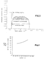
- Fig. 3 is a graphical representation of the thickness variation across the width of a typical sheet such as might exist in a rolling mill today.
- Fig. 3 shows what is, approximately, a 81.3 cm strip and it is seen that the total variation of strip thickness throughout the major portion of the width is represented by that region represented by crown.
- the strip thickness drops off rather abruptly. This is referred to here as the feather region.
- this abrupt slope or feather region is located, in this example, the inspection point in accordance with the Underwriters Laboratories' standards earlier mentioned. Thus considerable overweight will exist in this strip due to feather, more, in this example, than is due to strip crown.
- a perfectly rolled strip would have no crown and no feather such that the total depiction as shown in Fig. 3 would be a rectangular configuration without crown or feather. Such, however, is not practical and since the inspection point is as indicated, it is at least as important to reduce feather as to reduce crown in improving the efficiency of the rolling process.
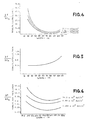
- Figs. 4 through 7 are various graphical representation useful in understanding the method of the present invention.
- Fig. 4 is the partial derivative of roll force per unit of width with respect to the targeted or desired roll strip crown C s while Fig. 5 is partial derivative of roll force per unit of width with respect to the roll crown C R .
- Fig. 6 is the partial derivative of roll force per unit of width with respect to the strip entry crown C E ; that is, the crown of the strip as it enters the rolling stand.
- Fig. 7 is the partial derivative of the roll crown with respect to the force of the roll bending system. All of the depictions of Figs. 4 through 7 are shown as plotted against the width of the workpiece in inches. It is noted that Figs. 4, 5 and 6 are identical to Figs. 2, 3 and 4 of the referenced patent 4,137,741 excepting that the labeling of the ordinate axis has been modified to conform with the language used in this specification, as will be more fully understood as this description proceeds.
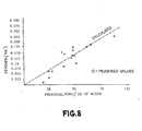
- Fig. 8 shows the results of field tests designed to confirm the relationship between rolling pressure and strip edge taper employed in the present method.
- edge taper or feather can be reduced by reducing the rolling pressure on the last pass of the strip through a mill stand. This reduction in pressure, or force per unit of width, must, however, be made within the constraints of strip crown and flatness as defined by the two aforementioned Fapiano et al. patents, particularly patent no. 4,137,741.
- the first step in the method of the present invention is to find the limit of the force per unit of strip width (Flimit) for a selected maximum allowable edge taper.
- Flimit the limit of the force per unit of strip width
- the factor 2 relates to the fact that there are two workrolls while /3 is an adjustment from plane 2 to three-dimensional strain at the strip edge.
- the 2000 factor is for converting tons to pounds while 0.9 is an experienced adjustment for overstatement of roll deformation by Hitchcock's equation.
- Equation (1) is essentially similar to that of Sertz (H. Hertz “Geracee Werke”, Vol. I, Leipzig 1895) for compression of a cylinder and flat plate, with the length of the contact arc in accordance with Hitchcock using the shell elastic modulus, and an experimental adjustment factor.
- the results of tests planned by the inventor of the present method to produce a wide range of rolling pressures are shown in Fig. 8, along with edge tapers calculated by equation (1).
- the next step is to determine the roll crown (C R ) that will produce the target crown (C s ) with the maximum allowable pressure F l i m i t as defined above. In the preferred embodiment of the present invention, this is achieved in accordance with the method as set forth in the aforementioned U.S. patent 4,137,741. In that patent the force per unit width to achieve the target crown is defined as "F" and is given by the equation: wherein:
- equation (4) may be rewritten as:
- This C R is, as was earlier stated, the roll crown which will produce the target crown at the maximum allowable pressure, F limit .
- the above calculations are, of course, performed in the computer 24 (Fig. 1) using stored values corresponding to the curves of Figs. 4, 5 and 6.
- the roll crown is adjusted by adjusting the roll bending force to correct roll crown "errors"; i.e., the differences between desired and actual roll crowns.
- the actual workroll crown is comprised, essentially of the sum of four components. These are:
Landscapes
- Engineering & Computer Science (AREA)
- Mechanical Engineering (AREA)
- Control Of Metal Rolling (AREA)
Applications Claiming Priority (2)
| Application Number | Priority Date | Filing Date | Title |
|---|---|---|---|
| US06/371,366 US4718262A (en) | 1982-04-23 | 1982-04-23 | Method for controlling edge taper in metal rolling mill |
| US371366 | 1982-04-23 |
Publications (2)
| Publication Number | Publication Date |
|---|---|
| EP0092741A1 true EP0092741A1 (fr) | 1983-11-02 |
| EP0092741B1 EP0092741B1 (fr) | 1986-05-28 |
Family
ID=23463687
Family Applications (1)
| Application Number | Title | Priority Date | Filing Date |
|---|---|---|---|
| EP83103598A Expired EP0092741B1 (fr) | 1982-04-23 | 1983-04-14 | Procédé de contrôle de l'amincissement du bord dans les laminoirs à feuillards en métaux |
Country Status (5)
| Country | Link |
|---|---|
| US (1) | US4718262A (fr) |
| EP (1) | EP0092741B1 (fr) |
| JP (1) | JPS58212805A (fr) |
| CA (1) | CA1211533A (fr) |
| DE (1) | DE3363720D1 (fr) |
Cited By (1)
| Publication number | Priority date | Publication date | Assignee | Title |
|---|---|---|---|---|
| CN115488163A (zh) * | 2022-10-31 | 2022-12-20 | 中冶南方工程技术有限公司 | 一种可协调各机架轧制压力的连轧机机组压下量获取方法 |
Families Citing this family (3)
| Publication number | Priority date | Publication date | Assignee | Title |
|---|---|---|---|---|
| US5239851A (en) * | 1989-05-31 | 1993-08-31 | Hitachi, Ltd. | Rolling method of multi-high rolling mill for obtaining accurate sheet crown |
| US5653137A (en) * | 1989-05-31 | 1997-08-05 | Hitachi, Ltd. | Five-high rolling mill |
| EP3599038A1 (fr) * | 2018-07-25 | 2020-01-29 | Primetals Technologies Austria GmbH | Procédé et dispositif de détermination du contour de bande latéral d'une bande métallique en mouvement |
Citations (3)
| Publication number | Priority date | Publication date | Assignee | Title |
|---|---|---|---|---|
| US3312092A (en) * | 1962-10-25 | 1967-04-04 | Moeller & Neumann Verwalt Ges | Control arrangement for level rolling metal plates and sheets in reversible rolling mills |
| US3938360A (en) * | 1973-05-02 | 1976-02-17 | Hitachi, Ltd. | Shape control method and system for a rolling mill |
| US4137741A (en) * | 1977-12-22 | 1979-02-06 | General Electric Company | Workpiece shape control |
Family Cites Families (2)
| Publication number | Priority date | Publication date | Assignee | Title |
|---|---|---|---|---|
| US3630055A (en) * | 1969-05-14 | 1971-12-28 | Gen Electric | Workpiece shape control |
| JPS5613526A (en) * | 1979-07-11 | 1981-02-09 | Tdk Corp | Magnetic recording medium |
-
1982
- 1982-04-23 US US06/371,366 patent/US4718262A/en not_active Expired - Lifetime
-
1983
- 1983-04-14 EP EP83103598A patent/EP0092741B1/fr not_active Expired
- 1983-04-14 DE DE8383103598T patent/DE3363720D1/de not_active Expired
- 1983-04-21 JP JP58069324A patent/JPS58212805A/ja active Granted
- 1983-04-22 CA CA000426486A patent/CA1211533A/fr not_active Expired
Patent Citations (3)
| Publication number | Priority date | Publication date | Assignee | Title |
|---|---|---|---|---|
| US3312092A (en) * | 1962-10-25 | 1967-04-04 | Moeller & Neumann Verwalt Ges | Control arrangement for level rolling metal plates and sheets in reversible rolling mills |
| US3938360A (en) * | 1973-05-02 | 1976-02-17 | Hitachi, Ltd. | Shape control method and system for a rolling mill |
| US4137741A (en) * | 1977-12-22 | 1979-02-06 | General Electric Company | Workpiece shape control |
Non-Patent Citations (1)
| Title |
|---|
| IRON AND STEEL ENGINEER, vol. 54, no. 9. September 1977, Pittsburgh S. WILMOTTE, M. ECONOMOPOULOS, R. COLIN, G. THOMAS "A New Approach to the Computer Setup of the Hot Strip Mill" pages 70-76 * |
Cited By (1)
| Publication number | Priority date | Publication date | Assignee | Title |
|---|---|---|---|---|
| CN115488163A (zh) * | 2022-10-31 | 2022-12-20 | 中冶南方工程技术有限公司 | 一种可协调各机架轧制压力的连轧机机组压下量获取方法 |
Also Published As
| Publication number | Publication date |
|---|---|
| EP0092741B1 (fr) | 1986-05-28 |
| US4718262A (en) | 1988-01-12 |
| JPS58212805A (ja) | 1983-12-10 |
| DE3363720D1 (en) | 1986-07-03 |
| CA1211533A (fr) | 1986-09-16 |
| JPH0555204B2 (fr) | 1993-08-16 |
Similar Documents
| Publication | Publication Date | Title |
|---|---|---|
| US3253438A (en) | Automatic strip gauge control for a rolling mill | |
| Sellars | Computer modelling of hot-working processes | |
| US3902345A (en) | Control device for rolling mill | |
| EP0156650B1 (fr) | Procédé et dispositif pour régler le profil d'un feuillard | |
| AU697496B2 (en) | Method and apparatus for the control of rolling mills | |
| US3518858A (en) | Method of continuously controlling the correcting apparatus for workpiece shape during rolling | |
| US3934438A (en) | Method of long-edge shape control for tandem rolling mill | |
| JP2000317511A (ja) | 金属製品の圧延方法 | |
| US5086399A (en) | Method and apparatus for setting-up rolling mill roll gaps | |
| US3938360A (en) | Shape control method and system for a rolling mill | |
| US3630055A (en) | Workpiece shape control | |
| EP0092741B1 (fr) | Procédé de contrôle de l'amincissement du bord dans les laminoirs à feuillards en métaux | |
| EP0647164B1 (fr) | Commande de la planeite du laminage d'une bande | |
| US4137741A (en) | Workpiece shape control | |
| EP0087083B1 (fr) | Méthode et dispositif de commande de calibre pour un laminoir à jeu de cylindres multiple | |
| Guo | Optimal profile and shape control of flat sheet metal using multiple control devices | |
| US6220068B1 (en) | Process and device for reducing the edge drop of a laminated strip | |
| JPH0474084B2 (fr) | ||
| US3537285A (en) | Prestressed rolling mill and control | |
| KR100325332B1 (ko) | 열연판폭방향두께프로파일을고려한판크라운예측방법 | |
| US3890817A (en) | Methods of rolling strip materials, and strip materials rolled thereby | |
| US3391557A (en) | Gauge control rolling mills and methods of rolling | |
| JPS6323848B2 (fr) | ||
| JPH05269516A (ja) | 厚板圧延の形状制御方法 | |
| JPH0899103A (ja) | 板圧延における板クラウンおよび形状制御方法 |
Legal Events
| Date | Code | Title | Description |
|---|---|---|---|
| PUAI | Public reference made under article 153(3) epc to a published international application that has entered the european phase |
Free format text: ORIGINAL CODE: 0009012 |
|
| AK | Designated contracting states |
Designated state(s): CH DE FR GB IT LI SE |
|
| 17P | Request for examination filed |
Effective date: 19840412 |
|
| GRAA | (expected) grant |
Free format text: ORIGINAL CODE: 0009210 |
|
| AK | Designated contracting states |
Kind code of ref document: B1 Designated state(s): CH DE FR GB IT LI SE |
|
| PG25 | Lapsed in a contracting state [announced via postgrant information from national office to epo] |
Ref country code: LI Effective date: 19860528 Ref country code: IT Free format text: LAPSE BECAUSE OF FAILURE TO SUBMIT A TRANSLATION OF THE DESCRIPTION OR TO PAY THE FEE WITHIN THE PRESCRIBED TIME-LIMIT;WARNING: LAPSES OF ITALIAN PATENTS WITH EFFECTIVE DATE BEFORE 2007 MAY HAVE OCCURRED AT ANY TIME BEFORE 2007. THE CORRECT EFFECTIVE DATE MAY BE DIFFERENT FROM THE ONE RECORDED. Effective date: 19860528 Ref country code: FR Free format text: THE PATENT HAS BEEN ANNULLED BY A DECISION OF A NATIONAL AUTHORITY Effective date: 19860528 Ref country code: CH Effective date: 19860528 |
|
| PG25 | Lapsed in a contracting state [announced via postgrant information from national office to epo] |
Ref country code: SE Effective date: 19860531 |
|
| REF | Corresponds to: |
Ref document number: 3363720 Country of ref document: DE Date of ref document: 19860703 |
|
| REG | Reference to a national code |
Ref country code: CH Ref legal event code: PL |
|
| EN | Fr: translation not filed | ||
| PLBE | No opposition filed within time limit |
Free format text: ORIGINAL CODE: 0009261 |
|
| STAA | Information on the status of an ep patent application or granted ep patent |
Free format text: STATUS: NO OPPOSITION FILED WITHIN TIME LIMIT |
|
| 26N | No opposition filed | ||
| REG | Reference to a national code |
Ref country code: GB Ref legal event code: IF02 |
|
| PGFP | Annual fee paid to national office [announced via postgrant information from national office to epo] |
Ref country code: GB Payment date: 20020416 Year of fee payment: 20 |
|
| PGFP | Annual fee paid to national office [announced via postgrant information from national office to epo] |
Ref country code: DE Payment date: 20020418 Year of fee payment: 20 |
|
| PG25 | Lapsed in a contracting state [announced via postgrant information from national office to epo] |
Ref country code: GB Free format text: LAPSE BECAUSE OF EXPIRATION OF PROTECTION Effective date: 20030413 |
|
| REG | Reference to a national code |
Ref country code: GB Ref legal event code: PE20 |