EP0092824A2 - Récolteuse de blé de semence - Google Patents
Récolteuse de blé de semence Download PDFInfo
- Publication number
- EP0092824A2 EP0092824A2 EP83103991A EP83103991A EP0092824A2 EP 0092824 A2 EP0092824 A2 EP 0092824A2 EP 83103991 A EP83103991 A EP 83103991A EP 83103991 A EP83103991 A EP 83103991A EP 0092824 A2 EP0092824 A2 EP 0092824A2
- Authority
- EP
- European Patent Office
- Prior art keywords
- ears
- brushes
- rotor
- conveying
- crop
- Prior art date
- Legal status (The legal status is an assumption and is not a legal conclusion. Google has not performed a legal analysis and makes no representation as to the accuracy of the status listed.)
- Granted
Links
- 210000005069 ears Anatomy 0.000 claims abstract description 67
- 238000003306 harvesting Methods 0.000 claims abstract description 38
- 230000002093 peripheral effect Effects 0.000 claims description 9
- 235000013339 cereals Nutrition 0.000 description 32
- 230000000694 effects Effects 0.000 description 6
- 239000010902 straw Substances 0.000 description 3
- 238000010521 absorption reaction Methods 0.000 description 2
- 230000008878 coupling Effects 0.000 description 2
- 238000010168 coupling process Methods 0.000 description 2
- 238000005859 coupling reaction Methods 0.000 description 2
- 241001124569 Lycaenidae Species 0.000 description 1
- -1 Polyethylene Polymers 0.000 description 1
- 239000004698 Polyethylene Substances 0.000 description 1
- 241000209140 Triticum Species 0.000 description 1
- 235000021307 Triticum Nutrition 0.000 description 1
- 238000010009 beating Methods 0.000 description 1
- 238000001514 detection method Methods 0.000 description 1
- 235000013399 edible fruits Nutrition 0.000 description 1
- 238000000034 method Methods 0.000 description 1
- 210000000056 organ Anatomy 0.000 description 1
- 239000004033 plastic Substances 0.000 description 1
- 229920003023 plastic Polymers 0.000 description 1
- 229920000573 polyethylene Polymers 0.000 description 1
- 238000004804 winding Methods 0.000 description 1
Images

Classifications
-
- A—HUMAN NECESSITIES
- A01—AGRICULTURE; FORESTRY; ANIMAL HUSBANDRY; HUNTING; TRAPPING; FISHING
- A01D—HARVESTING; MOWING
- A01D45/00—Harvesting of standing crops
- A01D45/30—Harvesting of standing crops of grass-seeds or like seeds
Definitions
- the invention relates to a harvesting device for a seed harvesting machine with two oppositely drivable, arranged on axes stripping members that form a variable passage gap for receiving the crop and feed the seeds to a downstream conveyor.
- a harvesting device for harvesting seeds which consists of a cylindrical brush, which cooperates with an inclined ramp and which introduces the ears located on the stalks into a gap provided between the outer circumference and the ramp and thus detaches the grains from the ears to then feed them to a downstream conveyor. Since the rotating brush only acts on one side of the ears while the underside of the ear lies on the top of the ramp, not all of the grains are always released from the ear, so that a relatively large loss occurs (US Pat. No. 2,853,845).
- a harvesting device for a harvesting machine is known (US Pat. No. 1,146,785), which has a reel above a cutting device, which feeds the crop to a conveying channel.
- a blower channel is provided behind the cutting device, from which conveying air enters the conveying channel and contributes to conveying the crop.
- a second blower ends with its outlet opening in the area of the inlet opening of the threshing device and supports the feeding of the crop to the threshing device.
- a seed harvesting machine is also known (US Pat. No. 2,460,029), which is only equipped with two rotating stripping members which have a plurality of blow bars. Bristle elements sit on the blow bars. The distances between the individual blow bars are very large so that the grains are only partially detached from the ears. Due to the large distance between the individual blow bars, the grains can accumulate in the pockets between the blow bars, so that they are flung out again via the scraper elements. Since the stripping elements have different peripheral speeds, the individual ears are treated unevenly.
- the harvesting device for harvesting seeds consists of a drivable reel, which is provided above a drum with beating bars, which is arranged at a distance from the reel and thus an inlet gap for Picking up ears located on stalks.
- the reel is equipped with numerous blow bars with rubber elements, which are intended to help the grains be removed from the ears. Since the front edge of the striking bars and the front edge of the conveyor chain of the striking drum are relatively small, only part of the surface of the ear is correctly grasped and therefore not all the grains are detached from the ear. Furthermore, there is a risk that the ears are pulled off the stalks with such a stripping device.
- the object of the invention is to design and arrange the drivable stripping members in such a way that the ears located on the stalks are easily removed from the Scraper organs are completely detected and the grains are released from the ears by mutual frictional action of the rotors, so that they can then be fed to a collecting container without loss.
- This object has been achieved in that the rotatable scraper members are designed as cylindrical brushes having an approximately continuous surface, the axis of the upper brush being slightly ahead of the axis of the lower brush, which is assigned at least one conveying fan.
- the individual ears which are on the stalks, are completely gripped and moved into a gap between the two brushes, so that the grains are completely detached from the ears by the frictional action of the brushes acting on the ears without the ears being pulled from the stalks.
- the ears are brought into an inclined position so that they easily get into the gap between the two brushes.
- the rotating brushes and an additional conveying fan generate a sufficient flow of conveying air so that the crop can be transported into a collecting container without mechanical conveying elements.
- the cylindrical outer surface of the lower brush lies approximately below the seeds contained in the ears and the axis of the upper brush lies above the seeds of the still standing crop contained in the ears. Due to the advantageous position of the lower brush with respect to the standing crop, even broken ears can easily be moved upwards into the gap between the two brushes, since the rotating brushes have a sufficiently large area that affects the ears over a large area .
- a good harvesting effect without winding up the ears or the straws on the brushes is achieved in that the peripheral speed of the two rotating brushes is between 18 and 27 m / sec.
- the harvesting device it is advantageous for the harvesting device to have a lower conveying fan in a fan housing, the outlet opening of which ends in the region of the lower brush and guides air along the rear of the brush backwards into the conveying device.
- a conveying blower provided in the harvesting device supports the conveying action of the grains loosened from the ears in the conveying channel, so that they can be discharged into a collecting container in a simple manner. Since the outlet opening of the conveying fan is drawn into the lower region of the lower brush, the grains flung downward are also caught by the air flow of the conveying fan and returned to the main air flow, which is caused by the rotating brushes, so that conveying losses are very small can be held.
- the harvesting device has a second conveying fan in a fan housing, which is provided with an outlet opening directed towards the rear of the passage gap and ending above the standing crop.
- the two have approximately the same diameter brushes are provided with radially extending bristles, which form a resistant, continuous, very small spaces with conveying surface when rotating against the crop. Since the two brushes both have approximately the same diameter and are driven at approximately the same speed, the two surfaces act on the ears on both sides evenly over a long period of time, since the spaces between the individual bristles are so minimal that the ears cannot penetrate them. Thus, a good rubbing effect is exerted on the ears and the grains are easily removed. The frictional effect is also supported by the fact that the conveying surface offers sufficient resistance to the ears so that the grains are completely removed from the ears.
- a particularly advantageous peripheral speed of the brushes is considered to be a speed between 21 and 23 m / sec, with which it is ensured that the ears are not pulled off the stalks and get stuck in the surface of the brushes. Since the distances between the individual blow bars are normally relatively large in the case of rotatable blow bars, which can be covered, for example, with rubber elements, no frictional effect is exerted on the ears over a certain area between the individual blow bars of the stripping elements. This disadvantage does not occur due to the bristles lying close together, since these form a continuous friction surface, particularly when the brushes are rotating, which act on the ears over a long period of time.
- the brushes can be driven individually by motors at the same or different speeds. Since the two brushes can be driven at the same speed, the ears are treated equally on both sides, thus ensuring that the grains are easily removed from the ears. However, if it is useful for certain types of fruit, the brushes can also be driven at different speeds.
- the axes for receiving the two rotating brushes can be adjusted individually or together to change the width of the gap or for adjustment in an approximately horizontal plane and are arranged on support arms. Due to the possibility of adjusting the brushes provided on the support arms, these can be adjusted accordingly to different types of crop, in order to ensure optimal detection of the crop in the gap between the two brushes.
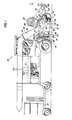
- 10 denotes a self-propelled seed harvester, which has a chassis 12, on the front of which a vertically adjustable harvesting device 14 with a housing 16 is arranged.
- the harvesting device 14 is connected to the seed harvesting machine 10 via a coupling device 18, to which one or more upper links 20 belong, which are connected at one end to the seed harvesting machine 10 and at the other ends with their front ends in an articulated manner to rear ends of the arms 22.
- the front ends of the arms 22 are articulated to the housing 16.
- the coupling device 18 also has lower links 24 which are connected at one end to the seed harvester 10 and at the other end to the housing 16.
- the upper and lower links 20 and 24 are connected to one another via tension springs 26.
- the harvesting device 14 can be raised or lowered via hydraulic cylinders 28 which are connected at one end to the chassis 12 and at the other end to the links 20 and can be actuated via a hydraulic control system.
- the housing 16 has two side walls 30 which are connected via a transverse wall, not shown in the drawing, to which the lower links 24 are connected.
- a conveyor channel 32 is connected to the housing 16 for receiving and for forwarding the grains or the seeds separated from the ears.
- the conveyor channel 32 ends above a trailer having a collecting container 33, which is coupled to the harvesting machine 10.
- the conveyor channel 32 consists of a bottom 36, an upper wall 34 and side walls 38.
- the side walls 38 of the conveyor channel 32 are flush with the side walls 30 of the housing 16.
- the receiving part or the inlet opening 39 of the conveying channel 32 is located between the side walls 30 of the harvesting device 14, immediately telbar behind a crop stripping device 41, which is provided in the front region of the harvesting device 14.
- a first conveying fan 50 which generates an air pressure which has overpressure.
- the conveying blower 50 is received in a blower housing 51 which is provided with an outlet opening 48, via which air enters a guide duct 52 and then into the inlet opening of the conveying duct 32.
- a slight negative pressure is generated behind the crop stripping device 41 via the air flow entering the conveying channel 32.
- the guide channel 52 is also formed from the side walls 30 of the housing 16 and a wall 53 which extends away from the delivery channel 32 and an upright end face 54 and a floor 56 which extends between the side walls 30 and the floor 36 of the delivery channel 32.
- the end face 54 forms an upright guide device which deflects the air flow.
- the inlet opening or the inlet channel 39 of the conveying channel 32 ends immediately in front of the bottom 56 and the upright end face 54, which thus forms a gap with the bottom 36 through which the air flow is conducted.
- the air flow picks up the grains harvested by means of the crop stripping device 41 and conveys them to the collecting container 33.
- a second conveying fan 60 which generates an air flow which is directed towards the rear in the main conveying direction of the crop stripping device 41.
- the conveying fan 60 has a conveying duct 62 which is connected to a curved guide device 66 is provided in its front area to redirect the airflow accordingly.
- the guide device 66 is ver by means of side parts 67 adjustably connected to the conveyor channel 62 so that the inclination of the guide device can be varied accordingly.
- the air flow in the conveying channel 62 is directed downwards and backwards against the ears or stalks of the crop in front of the crop stripping device 41 in order to press the stalks ST backwards and to bring the ears H of the crop C into a corresponding position (FIG. 3) , so that they can be correctly gripped by the crop stripping device 41.
- the crop stripping device 41 has an upper and lower rotor 82, 84, which are arranged on transverse axes 86, 88 with respect to the conveying direction of the crop.
- the rotors 82, 84 have corresponding stripping elements or are designed as rotating brushes which strip the grains from the ears.
- the rotors 82 and 84 designed as rotating brushes 85 and 87 in FIG. 3 can be made, for example, of relatively resistant or stiff plastic bristles, such as e.g. Polyethylene bristles.
- the individual bristles 85, 87 are so long and at their radial outer ends so far apart that they form a correspondingly resistant outer surface which, when it comes into contact with the crop, wipes the individual grains from the ears accordingly .
- the ends of the bristles can, for example, be at a distance from one another of between 1.27 cm and 3.08 cm.
- the cross section of the bristles can, for example, be elliptical, the individual bristles being corrugated or crimped, or corrugated or similar.
- the diameter of the rotors 82 and 84 can be chosen as desired.
- the rotors preferably have a diameter which is between 15 and 20 cm.
- the axles 86 and 88 receiving the rotors 82 and 84 are rotatably received at the ends in bearings 90, 92 on both sides of the housing 16.
- the upper bearings 90 of the upper rotor 82 are arranged at the front ends of adjustable support arms 94 and the lower bearings 92 of the lower rotor 84 in lower, adjustable support arms 96.
- the brushes 85, 87 can be raised or lowered independently of one another in order in this way to adapt the crop stripping device 41 to the different height of the crop.
- the brushes 85, 87 are preferably close together and form a gap or a gap-shaped feed zone 98 between their outer circumference of the rotors into which the ears are inserted, so that the grains can be removed or rubbed out of the ears. For this reason, rotors 82 and 84 rotate in opposite directions to one another, with the front of the upper rotor moving downward while the front of the lower rotor moving upward. The bristle ends of the two brushes 85, 87 thus migrate backwards through the gap 98 or through the feed zone 98.
- the rotors 82 and 84 are equipped in such a way that the entry of the ears into the gap 98 is made possible or facilitated.
- the lower side of the lower rotor 82 lies below the plane of the ears of the crop still standing, while the axis of the upper rotor 82 lies above the ears of the crop still standing.
- the bristles 85 of the upper rotor 82 lie somewhat in front of the bristles 87 of the lower rotor 84, ie the vertical transverse plane of the rotor 82 lies in front of the vertical transverse transverse plane of the lower rotor 84.
- the upper bristles which catch ears growing on longer stalks can reach the gap 98, thereby pushing the ears down and into an inclined position, approximately in the direction corresponds to the air flow of the conveying fan 60.
- the ears placed in this position remain in this position or are pressed down or inclined even further by the upper rotor 82.
- the air flow caused by the conveying fan 60 is supported by the suction air caused by the two rotors 82 and 84 due to the high rotor speeds.
- the standing crop is thus influenced by the rearward air flow of the conveying fan 60 on the one hand and by the suction air of the lower conveying fan 50 and the suction air of the rotors 82 and 84 on the other hand.
- the stems of the crop are bent backwards and thereby get contact with the ends of the bristles in the area of the gap 98, so that the grains can be rubbed out or stripped from the ears.
- the upper conveyor blower 60 of the harvesting machine generates an air throughput of approximately 2.27 m 3 / sec, with a flow rate of approximately 44 m / sec at the outlet of the conveyor blower 60.
- the lower conveying fan 50 generates a flow rate of 2.05 m 3 / sec, the air passing through at a rate of 30 m / sec the gap 55 is passed.
- the stripped grains are added to the air stream of the harvesting device 14 described by means of the rotating bristles 85 and 87.
- the rear side of the rotor 84 is placed in such a way that the air flow of the lower conveying fan 50 is directed upward over the associated bristles 87 and thus reaches the conveying channel 32 and also detects the grains which have migrated out of the main air flow.
- the rotors 82, 84 advantageously have a circumferential speed that is between 18 and 27 m / sec.
- a peripheral speed of between 21 and 23 m / sec is also particularly advantageous in order to achieve a sufficient wiping action and absorption of the crop in the air stream. If the peripheral speed is too high, the crop is scattered indiscriminately in various directions, so that a corresponding loss occurs. If the peripheral speed is too low, a large part of the grains remain in the ears and the ears then tend to wind up on the rotors 82 and 84.
- the rotors are driven by two separate motors 102, which are provided on one side of the harvesting device 14 and can be driven, for example, via the hydraulic system of the seed harvesting machine 10.
- the two hydraulic motors are connected in series, so that the upper rotor 82 is driven faster than the lower rotor and a rubbing or rubbing effect is exerted on the untreated ears when they get into the gap 98.
- the Leakage losses from the upper engine are returned to the hydraulic system reservoir.
- the harvesting device 16 has straw dividers 110 which divide the standing crop in front of the rotors 82 and 84.
- the harvesting machine 10 travels over a field with standing grain C, for example wheat, although other grain can also be harvested with the harvesting machine according to the invention.
- standing grain C for example wheat, although other grain can also be harvested with the harvesting machine according to the invention.
- Grains which have not been supplied to the main air stream or have been carried out of the main air stream and then pass below the rotor 84 are caught by the air stream of the conveying fan 50 and conveyed back to the main air stream.
- the collected grains are then captured by the conveying channel 32 and fed to the collecting container 33 on a trailer vehicle.
- the seed harvester is smaller and less expensive than conventional harvesters because there is less coffee and straw.
- the use of the crop stripping device 41 ensures that the stems remain in the ground, so that smaller, narrower and less complicated working elements are necessary.
- the drive means can be significantly reduced.
- the peripheral speed of the rotors 82 and 84 is considered to be particularly advantageous since they ensure that the grains are adequately stripped from the ears without the stems being torn out of the ground.
- the advantageous placement of the two rotors relative to one another see FIG. 3) and the advantageous assignment of the rotors to the upper and and the lower air flow ensure an extremely good wiping result and a correspondingly good absorption of the grains in the conveying air.
Landscapes
- Life Sciences & Earth Sciences (AREA)
- Environmental Sciences (AREA)
- Combines (AREA)
- Outside Dividers And Delivering Mechanisms For Harvesters (AREA)
- Cleaning Of Streets, Tracks, Or Beaches (AREA)
- Harvesting Machines For Specific Crops (AREA)
Applications Claiming Priority (2)
| Application Number | Priority Date | Filing Date | Title |
|---|---|---|---|
| US371741 | 1982-04-26 | ||
| US06/371,741 US4738087A (en) | 1982-04-26 | 1982-04-26 | Harvester for stripping seed from a standing crop |
Publications (3)
| Publication Number | Publication Date |
|---|---|
| EP0092824A2 true EP0092824A2 (fr) | 1983-11-02 |
| EP0092824A3 EP0092824A3 (en) | 1984-10-17 |
| EP0092824B1 EP0092824B1 (fr) | 1988-08-10 |
Family
ID=23465227
Family Applications (1)
| Application Number | Title | Priority Date | Filing Date |
|---|---|---|---|
| EP83103991A Expired EP0092824B1 (fr) | 1982-04-26 | 1983-04-23 | Récolteuse de blé de semence |
Country Status (6)
| Country | Link |
|---|---|
| US (1) | US4738087A (fr) |
| EP (1) | EP0092824B1 (fr) |
| JP (1) | JPS58193613A (fr) |
| AU (1) | AU556245B2 (fr) |
| CA (1) | CA1196197A (fr) |
| DE (1) | DE3377612D1 (fr) |
Cited By (3)
| Publication number | Priority date | Publication date | Assignee | Title |
|---|---|---|---|---|
| US4790128A (en) * | 1984-09-27 | 1988-12-13 | National Research Development Corporation | Crop harvesting apparatus and methods |
| US4951453A (en) * | 1984-09-27 | 1990-08-28 | National Research Development Corporation | Crop harvesting apparatus and methods |
| CN103168572A (zh) * | 2013-04-18 | 2013-06-26 | 西南大学 | 一种双滚筒脱粒机构上的防谷粒溅落装置 |
Families Citing this family (8)
| Publication number | Priority date | Publication date | Assignee | Title |
|---|---|---|---|---|
| US4942727A (en) * | 1989-10-23 | 1990-07-24 | Ginn William D | Seed collector device for a mower |
| US5372002A (en) * | 1992-07-15 | 1994-12-13 | Hoechst Nor-Am Agrevo Inc. | Portable seed stripper apparatus |
| US6640530B1 (en) * | 2001-01-26 | 2003-11-04 | Lee Arbuckle | Harvester with cooperating brushes and combs |
| SG10201807380VA (en) | 2008-11-17 | 2018-09-27 | Xyleco Inc | Processing biomass |
| CN103238413A (zh) * | 2013-05-25 | 2013-08-14 | 韶关市丰一工贸有限公司 | 一种梳脱式联合收割机 |
| US8869498B1 (en) * | 2014-04-04 | 2014-10-28 | Martin Bremmer | Handheld harvester apparatus |
| US11224168B1 (en) | 2019-04-24 | 2022-01-18 | Martin Bremmer | Handheld harvester apparatus |
| CA3153443A1 (fr) * | 2019-10-01 | 2021-04-08 | Jay ENGLES | Recolteuse de cannabis et procedes d'utilisation associes |
Family Cites Families (18)
| Publication number | Priority date | Publication date | Assignee | Title |
|---|---|---|---|---|
| US1146785A (en) * | 1914-01-31 | 1915-07-20 | Charles Colahan | Grain-harvester. |
| US2065721A (en) * | 1935-11-07 | 1936-12-29 | Mutzbauer Jakob | Harvester |
| US2485713A (en) * | 1945-09-14 | 1949-10-25 | Erith M Dowd | Seed harvester |
| US2460029A (en) * | 1946-08-02 | 1949-01-25 | Russell M Ramp | Russian dandelion seed harvester |
| US2706373A (en) * | 1951-02-05 | 1955-04-19 | John L Nisbet | Method of harvesting grass seed |
| US2673438A (en) * | 1952-01-02 | 1954-03-30 | Ford Motor Co | Cotton stripper |
| US2674080A (en) * | 1952-04-07 | 1954-04-06 | Ford Motor Co | Cotton stripper |
| DE933789C (de) * | 1953-04-25 | 1955-10-06 | Excorna Pharmazeutische Praepa | Maschine zum Ernten sowie Verfahren und Maschine zur Erzeugung von Mutterkorn |
| GB809616A (en) * | 1956-08-07 | 1959-02-25 | Nat Res Dev | Machines for harvesting seeds from standing crops |
| US2853845A (en) * | 1956-09-10 | 1958-09-30 | Charles O Smith | Seed harvester |
| FR1240440A (fr) * | 1958-11-24 | 1960-09-02 | Moissonneuse perfectionnée | |
| US3184905A (en) * | 1964-05-25 | 1965-05-25 | Ramon L Hillier | Grain harvester |
| US3555790A (en) * | 1968-08-05 | 1971-01-19 | Univ Iowa State Res Found | Aerodynamic grain handling system |
| US3828531A (en) * | 1969-03-14 | 1974-08-13 | Univ Iowa State Res Found | Vortex fan means for a crop gathering apparatus |
| US3581483A (en) * | 1969-03-26 | 1971-06-01 | Victor P Kohl | Asparagus harvester and method of harvesting asparagus |
| JPS5122761Y2 (fr) * | 1972-05-31 | 1976-06-11 | ||
| JPS5227057A (en) * | 1975-08-27 | 1977-03-01 | Rotterdamsche Droogdok Mij | Method of processing incomplete parts or cracks of metal workpiece generally having thick wall |
| CA1107599A (fr) * | 1981-02-26 | 1981-08-25 | Shaukat A. Mcdoom | Moissonneuse-batteuse mcdoom |
-
1982
- 1982-04-26 US US06/371,741 patent/US4738087A/en not_active Expired - Lifetime
-
1983
- 1983-03-09 AU AU12190/83A patent/AU556245B2/en not_active Expired
- 1983-04-23 EP EP83103991A patent/EP0092824B1/fr not_active Expired
- 1983-04-23 DE DE8383103991T patent/DE3377612D1/de not_active Expired
- 1983-04-25 CA CA000426654A patent/CA1196197A/fr not_active Expired
- 1983-04-26 JP JP58073704A patent/JPS58193613A/ja active Granted
Cited By (4)
| Publication number | Priority date | Publication date | Assignee | Title |
|---|---|---|---|---|
| US4790128A (en) * | 1984-09-27 | 1988-12-13 | National Research Development Corporation | Crop harvesting apparatus and methods |
| US4951453A (en) * | 1984-09-27 | 1990-08-28 | National Research Development Corporation | Crop harvesting apparatus and methods |
| CN103168572A (zh) * | 2013-04-18 | 2013-06-26 | 西南大学 | 一种双滚筒脱粒机构上的防谷粒溅落装置 |
| CN103168572B (zh) * | 2013-04-18 | 2015-10-28 | 西南大学 | 一种双滚筒脱粒机构上的防谷粒溅落装置 |
Also Published As
| Publication number | Publication date |
|---|---|
| JPH0424003B2 (fr) | 1992-04-23 |
| EP0092824B1 (fr) | 1988-08-10 |
| DE3377612D1 (en) | 1988-09-15 |
| AU556245B2 (en) | 1986-10-30 |
| CA1196197A (fr) | 1985-11-05 |
| EP0092824A3 (en) | 1984-10-17 |
| JPS58193613A (ja) | 1983-11-11 |
| AU1219083A (en) | 1983-11-03 |
| US4738087A (en) | 1988-04-19 |
Similar Documents
| Publication | Publication Date | Title |
|---|---|---|
| DE3854083T2 (de) | Apparat und verfahren zum ernten von feldfrüchten. | |
| DE3918393C2 (de) | Getreideerntemaschine | |
| DE3751350T2 (de) | Halmfruchterntevorrichtung. | |
| DE3587945T2 (de) | Ernteverfahren und -vorrichtung. | |
| EP0094036B1 (fr) | Dégageuse de récolte pour une récolteuse de grains | |
| EP1305998B1 (fr) | Dispositif d'introduction et de cueillage | |
| EP0181500B1 (fr) | Moissonneuse-batteuse | |
| EP0162431B1 (fr) | Machine de récolte | |
| DE19959282A1 (de) | Einzugs- und Pflückeinrichtung mit Häckseleinrichtung | |
| DE10028887A1 (de) | Einzugs- und Pflückeinrichtung | |
| DE1507195B2 (de) | Erntemaschine für stengeliges Halmgut, insbesondere Mais | |
| EP0092824A2 (fr) | Récolteuse de blé de semence | |
| DE3024593A1 (de) | Erntemaschine zur gewinnung von koernermais | |
| DE3414576C2 (fr) | ||
| DE3318554A1 (de) | Verfahren und vorrichtung zum gewinnen von grassamen | |
| DE2817174A1 (de) | Erntemaschine zur gewinnung von tierfutter aus mais | |
| EP3957157A1 (fr) | Agencement de doigts du cueilleur | |
| AT403754B (de) | Kürbiserntemaschine | |
| DE942055C (de) | Vorrichtung zum Dreschen und Vorreinigen von Kurzgetreide | |
| DE10257775A1 (de) | Einzugs- und Pflückeinrichtung | |
| EP4070642A1 (fr) | Appareil accessoire pour récolter des plantes sur tige doté d'une fente de cueillette située transversalement au sens de déplacement | |
| DE102020130219A1 (de) | Kornverlustverhinderungssystem mithilfe von Luftgebläsen | |
| DE1482199A1 (de) | Erntemaschine,insbesondere Maehdrescher | |
| DE3240423C2 (de) | Zieh- und Fördereinrichtung für auf Halmen oder Büscheln wachsende Feldfrüchte, vorwiegend Hülsenfrüchte | |
| DE19742110A1 (de) | Aufbereitungseinrichtung für landwirtschaftliches Halmgut |
Legal Events
| Date | Code | Title | Description |
|---|---|---|---|
| PUAI | Public reference made under article 153(3) epc to a published international application that has entered the european phase |
Free format text: ORIGINAL CODE: 0009012 |
|
| AK | Designated contracting states |
Designated state(s): BE DE FR GB IT |
|
| ITCL | It: translation for ep claims filed |
Representative=s name: LENZI & C. |
|
| EL | Fr: translation of claims filed | ||
| 17P | Request for examination filed |
Effective date: 19840413 |
|
| PUAL | Search report despatched |
Free format text: ORIGINAL CODE: 0009013 |
|
| AK | Designated contracting states |
Designated state(s): BE DE FR GB IT |
|
| GRAA | (expected) grant |
Free format text: ORIGINAL CODE: 0009210 |
|
| ITF | It: translation for a ep patent filed | ||
| RAP1 | Party data changed (applicant data changed or rights of an application transferred) |
Owner name: LUNDAHL, EZRA CORDELL |
|
| RIN1 | Information on inventor provided before grant (corrected) |
Inventor name: LUNDAHL, EZRA CORDELL |
|
| AK | Designated contracting states |
Kind code of ref document: B1 Designated state(s): BE DE FR GB IT |
|
| GBT | Gb: translation of ep patent filed (gb section 77(6)(a)/1977) | ||
| REF | Corresponds to: |
Ref document number: 3377612 Country of ref document: DE Date of ref document: 19880915 |
|
| ET | Fr: translation filed | ||
| PLBE | No opposition filed within time limit |
Free format text: ORIGINAL CODE: 0009261 |
|
| STAA | Information on the status of an ep patent application or granted ep patent |
Free format text: STATUS: NO OPPOSITION FILED WITHIN TIME LIMIT |
|
| 26N | No opposition filed | ||
| ITTA | It: last paid annual fee | ||
| PGFP | Annual fee paid to national office [announced via postgrant information from national office to epo] |
Ref country code: FR Payment date: 19950328 Year of fee payment: 13 |
|
| PG25 | Lapsed in a contracting state [announced via postgrant information from national office to epo] |
Ref country code: FR Effective date: 19951229 |
|
| REG | Reference to a national code |
Ref country code: FR Ref legal event code: ST |
|
| REG | Reference to a national code |
Ref country code: GB Ref legal event code: IF02 |
|
| PGFP | Annual fee paid to national office [announced via postgrant information from national office to epo] |
Ref country code: GB Payment date: 20020417 Year of fee payment: 20 |
|
| PGFP | Annual fee paid to national office [announced via postgrant information from national office to epo] |
Ref country code: BE Payment date: 20020418 Year of fee payment: 20 |
|
| PGFP | Annual fee paid to national office [announced via postgrant information from national office to epo] |
Ref country code: DE Payment date: 20020515 Year of fee payment: 20 |
|
| PG25 | Lapsed in a contracting state [announced via postgrant information from national office to epo] |
Ref country code: GB Free format text: LAPSE BECAUSE OF EXPIRATION OF PROTECTION Effective date: 20030422 |
|
| BE20 | Be: patent expired |
Owner name: *LUNDAHL EZRA CORDELL Effective date: 20030423 |
|
| REG | Reference to a national code |
Ref country code: GB Ref legal event code: PE20 |