EP0092919A2 - Einrichtung zum Absondern einer Leitung in einer hydraulischen Doppelleitung für Schiffsrudersysteme - Google Patents
Einrichtung zum Absondern einer Leitung in einer hydraulischen Doppelleitung für Schiffsrudersysteme Download PDFInfo
- Publication number
- EP0092919A2 EP0092919A2 EP83301881A EP83301881A EP0092919A2 EP 0092919 A2 EP0092919 A2 EP 0092919A2 EP 83301881 A EP83301881 A EP 83301881A EP 83301881 A EP83301881 A EP 83301881A EP 0092919 A2 EP0092919 A2 EP 0092919A2
- Authority
- EP
- European Patent Office
- Prior art keywords
- starboard
- activation
- port
- steering system
- deactivation
- Prior art date
- Legal status (The legal status is an assumption and is not a legal conclusion. Google has not performed a legal analysis and makes no representation as to the accuracy of the status listed.)
- Withdrawn
Links
Images
Classifications
-
- B—PERFORMING OPERATIONS; TRANSPORTING
- B63—SHIPS OR OTHER WATERBORNE VESSELS; RELATED EQUIPMENT
- B63H—MARINE PROPULSION OR STEERING
- B63H25/00—Steering; Slowing-down otherwise than by use of propulsive elements; Dynamic anchoring, i.e. positioning vessels by means of main or auxiliary propulsive elements
- B63H25/06—Steering by rudders
- B63H25/08—Steering gear
- B63H25/14—Steering gear power assisted; power driven, i.e. using steering engine
- B63H25/26—Steering engines
- B63H25/28—Steering engines of fluid type
- B63H25/30—Steering engines of fluid type hydraulic
-
- B—PERFORMING OPERATIONS; TRANSPORTING
- B63—SHIPS OR OTHER WATERBORNE VESSELS; RELATED EQUIPMENT
- B63H—MARINE PROPULSION OR STEERING
- B63H25/00—Steering; Slowing-down otherwise than by use of propulsive elements; Dynamic anchoring, i.e. positioning vessels by means of main or auxiliary propulsive elements
- B63H25/06—Steering by rudders
- B63H25/08—Steering gear
- B63H25/14—Steering gear power assisted; power driven, i.e. using steering engine
- B63H25/18—Transmitting of movement of initiating means to steering engine
- B63H25/22—Transmitting of movement of initiating means to steering engine by fluid means
Definitions
- This invention relates generally to hydraulic steering systems.
- Much of the steering gear presently utilised aboard ships comprises two pump units one usually located on the vessel's port side, and the other on the starboard. These units are interconnected to drive a common set of hydraulic rudder actuators. Due to the common connection, a loss of fluid can render both pumps inoperable. Most such systems include manually operated valves that allow the pump units to be isolated and the hydraulic actuators to be separated into two independent steering systems. However, during failure, the journey to the steering gear chamber to shift valves wastes precious time which may jeopardise the vessel's safety. In a catastropic incident, such disabling loss of fluid resulted in a super tanker running aground, breaking in two, and spilling its cargo of oil into the sea.
- an object of the present invention is to provide an apparatus for automatically or remotely dividing a two pump unit hydraulic steering system, upon detection of dangerous loss of fluid, into two independent steering systems, in order to maintain steering capability.
- an isolation valve is activated by a control unit so as to block the interconnecting piping, thus dividing the system in two.
- the pump unit associated with the leak-free side of the system is operated, and a by-pass valve is activated which relieves resistance by the ram group associated with the leaking side to motion imparted by the ram group associated with the leak-free side, thus maintaining steering capability on the leak-free side of the system.
- loss of fluid is sensed by a leak detection tank employing a float-type switch.
- the by-pass valves each comprise a solenoid pilot operated directional control valve, and the isolation valve comprises a pilot operated directional control valve.
- the control unit comprises conventional electrohydraulic devices for regulating the operations of the system.
- the system comprises an apparatus, with test facility, for detecting a dangerous fluid loss in the hydraulic steering system which has two pump units, two reservoirs, two ram groups, and interconnecting piping which couples each of the pump units to each of the ram groups.
- the system Upon detecting such a loss, the system is automatically or remotely divided into two independent steering systems, in order to maintain steering capability. Upon repair of the leak, the system can be returned to normal operation.
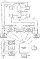
- the system comprises an isolation valve 10, capable of activation and deactivation, which upon activation blocks interconnecting pipes 11 and 12 between a starboard pump unit 13 and a port pump unit 14, and which upon deactivation unblocks these pipes.
- a starboard by-pass valve 15, capable of activation and deactivation is provided and upon activation, couples the interconnecting pipes 11 and 12 on the starboard side of the isolation valve, and upon deactivation uncouples these pipes.
- a port by-pass valve 16 capable of activation and deactivation, is also provided and upon activation couples the interconnecting pipes 11 and 12 on the port side of the isolation valve, and upon deactivation uncouples these pipes.
- a system leak detector 17 senses any dangerous loss of fluid in the system.
- a starboard leak detector 18 senses any dangerous loss of fluid in the isolated starboard steering system
- a port leak detector 19 senses any dangerous loss of fluid in the isolated port steering system.
- An alarm panel 20, responsive to each of the leak detectors, 17, 18 and 19, provides an alert for each dangerous loss of fluid detected.
- a reset mechanism 22 upon activation, returns the isolated steering system, through the control unit, to normal operation.
- a test mechanism 23, upon activation, supplies a simulated dangerous loss of fluid signal to the control unit.
- the steering system generally operates on only one pump unit at a time. When deactivated, a pump unit does not permit the entrance of fluid. Assuming, without loss of generality, that the steering system is initially operating on the starboard pump unit 13, and that loss of fluid is occurring in the system, the invention functions as follows.
- the system leak detector 17 ultimately senses a dangerous loss of fluid, and alarm panel 20 reacts by providing an alert.
- the isolation valve 10 and port by-pass valve 16 are activated through the control unit 21.
- the activated isolation valve 10 blocks the interconnecting pipes 11 and 12 between the starboard pump unit 13 and the port pump unit 14, dividing the steering system in two.
- the activated port by-pass valve 16 couples the interconnecting pipes 11 and 12 on the port side of isolation valve 10.
- the starboard leak detector 18 will fail to sense a dangerous loss of fluid, and steering is now conducted on the starboard side of the system by the starboard pump unit 13 operating a starboard ram group 24.
- the starboard leak detector 18 Assuming, alternatively, a leak in the piping on the starboard side of the isolation valve 10, the starboard leak detector 18 ultimately senses a dangerous loss of fluid, and alarm panel 20 reacts by providing an alert.
- control unit 21 In response to the sensing of the starboard leak, the starboard pump unit 13 is deactivated, the port pump unit 14 is activated, the starboard by-pass valve 15 is activated, and the port by-pass valve 16 is deactivated. Steering is now conducted on the port side of the system by the port pump unit 14 operating the port ram group 25.
- the reset mechanism 22 Upon repair of the leak, the reset mechanism 22 is actuated so as to return, through the control unit 21, the isolated steering system to normal operation by deactivating the isolation valve 10, and whichever by-pass valve had been activated.
- the test mechanism 23 permits a check of the system by supplying a simulated dangerous loss of fluid signal to the control unit 21.
- each of the by-pass valves 15 and 16 comprises a solenoid pilot operated directional control valve (pilot refers to regulation of the valve by hydraulic pressure).
- the isolation valve 10 comprises a pilot operated directional control valve, and each of the leak detectors 17, 18 and 19 comprises a tank employing a float-type level switch.
- the alarm panel comprises lights and horns which simultaneously provide a visual and audio alert of the particular dangerous loss of fluid. Both the test and reset mechanisms comprise toggle switches and associated circuitry.
- the control unit 21 comprises conventional hydraulic and electrical devices for regulating the operation of the system as described above.
- the control unit 21 comprises a pilot pressure pump unit which supplies hydraulic pressure for regulating the isolation and by-pass valves 15 and 16.
- the electric circuitry of the control unit 21 comprises a time delay relay, responsive to the system leak detector 17 and operable to initiate isolation of the steering system only after an appropriate delay, to preclude mere sloshing of fluid from precipitating such action.
- the electric and hydraulic couplings between the various components of the system comprise conventional devices.
- control unit 21 The operations of the control unit 21 are carried out automatically in response to the various leak detectors 17, 18 and 19, or remotely in response to the various alerts provided by the alarm panel 20, or partly automatically and partly remotely.
Landscapes
- Chemical & Material Sciences (AREA)
- Engineering & Computer Science (AREA)
- Combustion & Propulsion (AREA)
- Mechanical Engineering (AREA)
- Ocean & Marine Engineering (AREA)
- Fluid-Pressure Circuits (AREA)
Applications Claiming Priority (2)
| Application Number | Priority Date | Filing Date | Title |
|---|---|---|---|
| US37103782A | 1982-04-23 | 1982-04-23 | |
| US371037 | 1995-01-10 |
Publications (2)
| Publication Number | Publication Date |
|---|---|
| EP0092919A2 true EP0092919A2 (de) | 1983-11-02 |
| EP0092919A3 EP0092919A3 (de) | 1983-11-30 |
Family
ID=23462233
Family Applications (1)
| Application Number | Title | Priority Date | Filing Date |
|---|---|---|---|
| EP83301881A Withdrawn EP0092919A3 (de) | 1982-04-23 | 1983-03-31 | Einrichtung zum Absondern einer Leitung in einer hydraulischen Doppelleitung für Schiffsrudersysteme |
Country Status (3)
| Country | Link |
|---|---|
| EP (1) | EP0092919A3 (de) |
| JP (1) | JPS58188793A (de) |
| CA (1) | CA1181323A (de) |
Families Citing this family (1)
| Publication number | Priority date | Publication date | Assignee | Title |
|---|---|---|---|---|
| JPH07100477B2 (ja) * | 1991-10-18 | 1995-11-01 | 株式会社トキメック | 船舶用操舵方法および装置 |
Family Cites Families (1)
| Publication number | Priority date | Publication date | Assignee | Title |
|---|---|---|---|---|
| EP0021732B2 (de) * | 1979-06-22 | 1988-04-13 | Vickers Limited | Hydraulische Rudersteuerung für Schiffe |
-
1982
- 1982-11-29 CA CA000416610A patent/CA1181323A/en not_active Expired
-
1983
- 1983-02-22 JP JP2839683A patent/JPS58188793A/ja active Pending
- 1983-03-31 EP EP83301881A patent/EP0092919A3/de not_active Withdrawn
Also Published As
| Publication number | Publication date |
|---|---|
| CA1181323A (en) | 1985-01-22 |
| JPS58188793A (ja) | 1983-11-04 |
| EP0092919A3 (de) | 1983-11-30 |
Similar Documents
| Publication | Publication Date | Title |
|---|---|---|
| US4705060A (en) | Detecting leaks in plumbing systems | |
| US4730634A (en) | Method and apparatus for controlling production of fluids from a well | |
| US4209986A (en) | Method of and apparatus for auxiliary control of fluid operated steering apparatus for ships, boats and the like | |
| US4623452A (en) | Dockside system for the collection and disposal of bilge water and waste oil | |
| US4365573A (en) | Steering gear for ships | |
| US4964437A (en) | Apparatus and method for control of oil leakage from damaged tanker | |
| JPH07501027A (ja) | 液体燃料あふれ防止システム | |
| US20040227635A1 (en) | High/low level alarm controller | |
| JPH0516876A (ja) | 損傷したタンカからの石油漏れを制御する装置 | |
| CA1181323A (en) | Hydraulic steering isolation system | |
| US5086722A (en) | Transient Damage Strategy | |
| GB2086333A (en) | Improved steering gear for ships | |
| US5156109A (en) | System to reduce spillage of oil due to rupture of ship's tank | |
| US4079806A (en) | Vehicle starting circuit to by-pass auxiliary steering system | |
| JPH09278190A (ja) | ローディグアーム | |
| JPS58133999A (ja) | 単ラム型油圧式舵取装置 | |
| EP0553922A1 (de) | System zum Überwachen von Ölleckagen aus einem beschädigten Tankschiff | |
| JPH0459240B2 (de) | ||
| SU931590A1 (ru) | Гидравлический привод рул судна | |
| Maxham | Steering Gear Requirements: Changes on the International and Domestic Scene | |
| Pomper | Paper 6: Hydraulic Control of Valves in Tankers | |
| JPS6327039Y2 (de) | ||
| JPH02164693A (ja) | 舵取機オートアイソレーシヨンシステム | |
| Soland et al. | The impact of extensive automation: a hopper dredge case study | |
| Pridvorov et al. | COMPRESSED AIR HYDRAULIC EMERGENCY STEERING GEAR |
Legal Events
| Date | Code | Title | Description |
|---|---|---|---|
| PUAI | Public reference made under article 153(3) epc to a published international application that has entered the european phase |
Free format text: ORIGINAL CODE: 0009012 |
|
| PUAL | Search report despatched |
Free format text: ORIGINAL CODE: 0009013 |
|
| AK | Designated contracting states |
Designated state(s): DE GB NL |
|
| AK | Designated contracting states |
Designated state(s): DE GB NL |
|
| 17P | Request for examination filed |
Effective date: 19840126 |
|
| STAA | Information on the status of an ep patent application or granted ep patent |
Free format text: STATUS: THE APPLICATION IS DEEMED TO BE WITHDRAWN |
|
| 18D | Application deemed to be withdrawn |
Effective date: 19860207 |
|
| RIN1 | Information on inventor provided before grant (corrected) |
Inventor name: RAYMOND, BRUCE CRANNELL Inventor name: RICHEY, RONALD KIRK |