EP0092962A2 - Affichage de la fréquence cardiaque - Google Patents
Affichage de la fréquence cardiaque Download PDFInfo
- Publication number
- EP0092962A2 EP0092962A2 EP83302206A EP83302206A EP0092962A2 EP 0092962 A2 EP0092962 A2 EP 0092962A2 EP 83302206 A EP83302206 A EP 83302206A EP 83302206 A EP83302206 A EP 83302206A EP 0092962 A2 EP0092962 A2 EP 0092962A2
- Authority
- EP
- European Patent Office
- Prior art keywords
- circuit
- signal
- absolute value
- amplitude
- heartbeat rate
- Prior art date
- Legal status (The legal status is an assumption and is not a legal conclusion. Google has not performed a legal analysis and makes no representation as to the accuracy of the status listed.)
- Withdrawn
Links
- 238000001514 detection method Methods 0.000 claims abstract description 22
- 239000003990 capacitor Substances 0.000 description 3
- 230000008602 contraction Effects 0.000 description 2
- 238000010586 diagram Methods 0.000 description 2
- 210000003414 extremity Anatomy 0.000 description 2
- 238000005259 measurement Methods 0.000 description 2
- 230000003321 amplification Effects 0.000 description 1
- 238000002565 electrocardiography Methods 0.000 description 1
- 230000008030 elimination Effects 0.000 description 1
- 238000003379 elimination reaction Methods 0.000 description 1
- 239000002184 metal Substances 0.000 description 1
- 238000003199 nucleic acid amplification method Methods 0.000 description 1
- 229910001220 stainless steel Inorganic materials 0.000 description 1
- 239000010935 stainless steel Substances 0.000 description 1
- 210000000707 wrist Anatomy 0.000 description 1
Images

Classifications
-
- A—HUMAN NECESSITIES
- A61—MEDICAL OR VETERINARY SCIENCE; HYGIENE
- A61B—DIAGNOSIS; SURGERY; IDENTIFICATION
- A61B5/00—Measuring for diagnostic purposes; Identification of persons
- A61B5/02—Detecting, measuring or recording for evaluating the cardiovascular system, e.g. pulse, heart rate, blood pressure or blood flow
- A61B5/024—Measuring pulse rate or heart rate
- A61B5/0245—Measuring pulse rate or heart rate by using sensing means generating electric signals, i.e. ECG signals
Definitions
- This invention relates to heartbeat rate indicators or pulse detection circuits (pulsimeters).
- heartbeat rate is measured by electrocardio- graphy where a small electric potential produced by the heart prior to contraction is detected. It has been proposed to measure heartbeat rate by detecting an electrocardiac potential signal induced between two metal electrodes in contact with different parts of the human body. Theoretically it should be possible to provide a small size and long life heartbeat rate indicator because the electrocardiac potential signal can be detected with low power consumption (about 100 pW).
- a heartbeat rate indicator comprising: a detection electrode for receiving an electrocardiac potential signal; an amplifier circuit for amplifying the electrocardiac potential signal; a filter circuit for removing noise from the amplified electrocardiac potential signal; and an amplitude detection circuit for detecting pulses having an amplitude greater than a predetermined amplitude, characterised by an absolute value circuit for producing an absolute value signal from the output signal of the filter circuit, the absolute value signal being fed to the amplitude detection circuit.
- the absolute value circuit includes a half-wave rectifier for half-wave rectifying the output signal from the filter circuit and an adder circuit for summing the half-wave rectified output signal from the half-wave rectifier with the output signal from the filter circuit.
- the heartbeat rate indicator may include an operational amplifier between the absolute value circuit and the amplitude detection circuit.
- Figure 1 shows the waveform of a human heartbeat.
- an electrocardiac potential signal induced between the right limb of the human body and the left limb is composed of a P-wave, a Q-R-S-wave and T-wave for each contraction of the heart.
- the amplitude of the Q-R-S-wave is the largest of the three waves and ranges from about 0.2 mV peak-to-peak and 1.5 mV peak-to-peak.
- Normally heartbeat rate indicators detect the Q-R-S-wave.
- FIG. 2 illustrates a heartbeat rate indicator such as that disclosed in British Patent Application No. 8232441.
- a detection electrode 1 is of stainless steel.
- the heartbeat rate indicator receives an electrocardiac potential signal.
- the ground potential may be applied to a casing of the heartbeat rate indicator when it is worn on the wrist of the left hand.
- the detection electrode 1 is connected to an amplifier circuit 3 via a capacitor 2 which acts as a DC elimination circuit.
- the amplifier circuit 3 is an operational amplifier with a plurality of resistors whose resistance ratio determines the amplification factor.
- the electrocardiac potential signal and noise amplified by the amplifier circuit are fed to a band-pass filter 4.
- the band-pass filter 4 consists of an operational amplifier, a resistor and two capacitors, the resistance ratio and the capacitance ratio determining the central frequency and the quality factor Q. Noise at commercial frequencies is eliminated by the band-pass filter 4 so that only the amplified electrocardiac potential signal appears at the output of the band-pass filter.
- the output signal from the band-pass filter 4 is fed to an AC amplitude detection circuit 5.
- the AC amplitude detection circuit 5 consists of a capacitor, a plurality of resistors and a voltage comparator and produces an output pulse signal only when the output signal from the band-pass filter has an amplitude greater than a predetermined value.
- the pulse signal from the AC amplitude detection circuit 5 is fed to an arithmetic logic circuit 6 which calculates the number of pulses produced per minute. That is to say produces an indication of heartbeat rate as the number of heartbeats per minute.
- Heartbeat rate can usually be determined with considerable accuracy using the heartbeat rate indicator of Figure 2.
- the heartbeat rate of some patients cannot be detected by it.
- Figure 3 shows the waveform of the heartbeat of one such patient.
- the waveform shown in Figure 3 differs from that of Figure 1 in that the amplitude change in the positive direction of the Q-R-S-wave is smaller than the amplitude change in the negative direction whereas the reverse is true for the waveform of Figure 1.
- An electrocardiac potential signal with the waveform shown in Figure 3 cannot be detected with accuracy using the heartbeat rate indicator of Figure 2 because the AC amplitude detection circuit 5 is designed to detect only a signal changing in the positive direction.
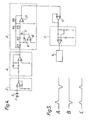
- FIG. 4 shows one embodiment of a heartbeat rate indicator according to the present invention. Like parts in Figures 2 and 4 have been designated by the same reference numerals and further description will be omitted.
- the heartbeart rate indicator of Figure 4 has an absolute value circuit 8, which is such that an electrocardiac potential signal which varies largely in the negative direction and which is hard to detect with the heartbeat rate indicator of Figure 2 is inverted and so is detectable.
- the absolute value circuit 8 consists of resistors R 11 , R 12 , R 13 , R 14 , R 15 , diodes 16, 17 and operational amplifiers 18, 19.
- An output signal from the band-pass filter 4 is connected to one side of the resistor R 11 , the other side of which is connected to the inverting input of the operational amplifier 18.
- the non-inverting input of the operational amplifier 18 is connected to ground potential and its output terminal is connected to the anode of the diode 16 and the cathode of the diode 17.
- the cathode of the diode 16 is connected to the inverting input of the operational amplifier 18.
- One side of the resistor R12 is connected to the inverting input of the operational amplifier 18 and the other side is connected to the anode of the diode 17.
- the resistors R 11 , R 12' the diodes'.16, 17 and the operational amplifier 18 constitute a half-wave rectifier.
- the output and the input of the half-wave rectifier are summed by an adding circuit which produces a full-wave rectified signal at the output of the absolute value circuit 8.
- the adding circuit consists of the resistor R 13 one side of which is connected to the anode of the diode 17 and the other side of which is connected to the inverting input of the operational amplifier 19.
- One side of the resistor R14 is connected to receive the output signal from the band-pass filter 4 fed to the absolute value circuit 8 and the other side of the resistor R 14 is connected to the inverting input of the operational amplifier 19.
- One side of the resistor R15 is connected to the inverting input of the operational amplifier 19 and the other side is connected to the output of the operational amplifier 19.
- the non-inverting input of the operational amplifier 19 is connected to ground potential and the output signal of the operational amplifier 19 is fed to the AC amplitude detection circuit 5 via an operational amplifier 19.
- Figure 5 illustrates the operation of the absolute value circuit 8.
- a signal A having a waveform consisting of alternately occurring positive and negative pulses is applied to the input of the absolute value circuit, a half-wave rectified signal B is produced by the half-wave rectifier and a full wave rectified signal C is produced at the output.
- the waveform signal A is given merely for ease of explanation.
- the absolute value circuit 8 receives an amplified and filter Q-R-S-wave from the band-pass filter 4.
- the provision of the absolute value circuit enables the absolute value of the Q-R-S-wave to be detected regardless of whether_it is positive going or negative going. Consequently heartbeat rate measurement can take place regardless of differences in polarity of the Q-R-S-waves of patients. Moreover, the pulse detection circuit is stable and highly precise.
Landscapes
- Health & Medical Sciences (AREA)
- Life Sciences & Earth Sciences (AREA)
- Engineering & Computer Science (AREA)
- Cardiology (AREA)
- Heart & Thoracic Surgery (AREA)
- Medical Informatics (AREA)
- Physiology (AREA)
- Biophysics (AREA)
- Pathology (AREA)
- Biomedical Technology (AREA)
- Signal Processing (AREA)
- Physics & Mathematics (AREA)
- Molecular Biology (AREA)
- Surgery (AREA)
- Animal Behavior & Ethology (AREA)
- General Health & Medical Sciences (AREA)
- Public Health (AREA)
- Veterinary Medicine (AREA)
- Measuring Pulse, Heart Rate, Blood Pressure Or Blood Flow (AREA)
- Measurement And Recording Of Electrical Phenomena And Electrical Characteristics Of The Living Body (AREA)
Applications Claiming Priority (2)
| Application Number | Priority Date | Filing Date | Title |
|---|---|---|---|
| JP72078/82 | 1982-04-28 | ||
| JP57072078A JPS58188427A (ja) | 1982-04-28 | 1982-04-28 | 脈拍検出回路 |
Publications (2)
| Publication Number | Publication Date |
|---|---|
| EP0092962A2 true EP0092962A2 (fr) | 1983-11-02 |
| EP0092962A3 EP0092962A3 (fr) | 1986-10-01 |
Family
ID=13479008
Family Applications (1)
| Application Number | Title | Priority Date | Filing Date |
|---|---|---|---|
| EP83302206A Withdrawn EP0092962A3 (fr) | 1982-04-28 | 1983-04-19 | Affichage de la fréquence cardiaque |
Country Status (2)
| Country | Link |
|---|---|
| EP (1) | EP0092962A3 (fr) |
| JP (1) | JPS58188427A (fr) |
Cited By (1)
| Publication number | Priority date | Publication date | Assignee | Title |
|---|---|---|---|---|
| DE3927709A1 (de) * | 1988-08-25 | 1990-03-15 | Cortec Associates Ltd | Einrichtung zur herzueberwachung |
Family Cites Families (4)
| Publication number | Priority date | Publication date | Assignee | Title |
|---|---|---|---|---|
| US3948250A (en) * | 1974-09-16 | 1976-04-06 | Becton, Dickinson And Company | Physiological information display |
| JPS5378695A (en) * | 1976-12-21 | 1978-07-12 | Seiko Instr & Electronics | Arm sphygmometer |
| FR2440197A1 (fr) * | 1978-11-06 | 1980-05-30 | Medtronic Inc | Amplificateur de detection de stimulateur cardiaque a la demande |
| US4248244A (en) * | 1979-04-06 | 1981-02-03 | Charnitski Richard D | Method for measuring heart beat rate and circuit means for same |
-
1982
- 1982-04-28 JP JP57072078A patent/JPS58188427A/ja active Pending
-
1983
- 1983-04-19 EP EP83302206A patent/EP0092962A3/fr not_active Withdrawn
Cited By (1)
| Publication number | Priority date | Publication date | Assignee | Title |
|---|---|---|---|---|
| DE3927709A1 (de) * | 1988-08-25 | 1990-03-15 | Cortec Associates Ltd | Einrichtung zur herzueberwachung |
Also Published As
| Publication number | Publication date |
|---|---|
| JPS58188427A (ja) | 1983-11-02 |
| EP0092962A3 (fr) | 1986-10-01 |
Similar Documents
| Publication | Publication Date | Title |
|---|---|---|
| US4248244A (en) | Method for measuring heart beat rate and circuit means for same | |
| TWI272090B (en) | Devices and methods for heart-rate measurement and wrist-watch incorporating same | |
| FI114282B (fi) | Menetelmä, järjestely ja sykemittari sydämen lyönnin tunnistamiseksi | |
| US4354505A (en) | Method of and apparatus for testing and indicating relaxation state of a human subject | |
| EP2086403B1 (fr) | Système de mesure de qualité de contact d'électrode d'ecg | |
| US5417221A (en) | Method and apparatus for distinguishing electric signal waveforms | |
| US4240442A (en) | Variable threshold R-wave detector | |
| EP1603636B1 (fr) | Detection d'evenements physiologiques | |
| JP5416333B2 (ja) | 心臓データを取得するための装置及び方法 | |
| US8886299B2 (en) | System and method for the analysis of electrocardiogram signals | |
| US4667682A (en) | Cardiac ambulatory monitor | |
| JPH0455714B2 (fr) | ||
| US5840039A (en) | Method and apparatus in connection with measuring the heartbeat rate of a person | |
| US5003983A (en) | Cardiac monitoring system | |
| EP0249819B1 (fr) | Stimulateur cardiaque pour entraîner le coeur humain | |
| US11576617B2 (en) | Detecting artifacts in a signal | |
| EP0249824B1 (fr) | Stimulateur cardiaque pour entraîner le coeur humain | |
| US4237903A (en) | QRS detector for EKG signals | |
| EP0092962A2 (fr) | Affichage de la fréquence cardiaque | |
| Kristiansen et al. | Design and evaluation of a handheld impedance plethysmograph for measuring heart rate variability | |
| EP1641388B1 (fr) | Dispositifs et procedes de mesure de frequence cardiaque et montre incorporant un tel dispositif | |
| WO1983001374A1 (fr) | Indicateur de l'activite cardiaque | |
| US3662746A (en) | Apparatus for detecting, analyzing and recording bioelectric potentials | |
| RU2076629C1 (ru) | Способ и устройство для селекции r-зубца кардиосигнала | |
| JPH05212006A (ja) | 心拍間隔計測装置 |
Legal Events
| Date | Code | Title | Description |
|---|---|---|---|
| PUAI | Public reference made under article 153(3) epc to a published international application that has entered the european phase |
Free format text: ORIGINAL CODE: 0009012 |
|
| AK | Designated contracting states |
Designated state(s): CH DE FR GB LI |
|
| PUAL | Search report despatched |
Free format text: ORIGINAL CODE: 0009013 |
|
| AK | Designated contracting states |
Kind code of ref document: A3 Designated state(s): CH DE FR GB LI |
|
| STAA | Information on the status of an ep patent application or granted ep patent |
Free format text: STATUS: THE APPLICATION IS DEEMED TO BE WITHDRAWN |
|
| 18D | Application deemed to be withdrawn |
Effective date: 19870402 |
|
| RIN1 | Information on inventor provided before grant (corrected) |
Inventor name: TABATA, JUNICHI |