EP0092975A1 - Dispositif pour recevoir et mélanger des échantillons - Google Patents
Dispositif pour recevoir et mélanger des échantillons Download PDFInfo
- Publication number
- EP0092975A1 EP0092975A1 EP83302261A EP83302261A EP0092975A1 EP 0092975 A1 EP0092975 A1 EP 0092975A1 EP 83302261 A EP83302261 A EP 83302261A EP 83302261 A EP83302261 A EP 83302261A EP 0092975 A1 EP0092975 A1 EP 0092975A1
- Authority
- EP
- European Patent Office
- Prior art keywords
- sample
- baffle
- pistons
- sub
- chamber
- Prior art date
- Legal status (The legal status is an assumption and is not a legal conclusion. Google has not performed a legal analysis and makes no representation as to the accuracy of the status listed.)
- Granted
Links
Images

Classifications
-
- E—FIXED CONSTRUCTIONS
- E21—EARTH OR ROCK DRILLING; MINING
- E21B—EARTH OR ROCK DRILLING; OBTAINING OIL, GAS, WATER, SOLUBLE OR MELTABLE MATERIALS OR A SLURRY OF MINERALS FROM WELLS
- E21B49/00—Testing the nature of borehole walls; Formation testing; Methods or apparatus for obtaining samples of soil or well fluids, specially adapted to earth drilling or wells
- E21B49/08—Obtaining fluid samples or testing fluids, in boreholes or wells
- E21B49/086—Withdrawing samples at the surface
-
- B—PERFORMING OPERATIONS; TRANSPORTING
- B01—PHYSICAL OR CHEMICAL PROCESSES OR APPARATUS IN GENERAL
- B01F—MIXING, e.g. DISSOLVING, EMULSIFYING OR DISPERSING
- B01F25/00—Flow mixers; Mixers for falling materials, e.g. solid particles
- B01F25/40—Static mixers
- B01F25/45—Mixers in which the materials to be mixed are pressed together through orifices or interstitial spaces, e.g. between beads
- B01F25/451—Mixers in which the materials to be mixed are pressed together through orifices or interstitial spaces, e.g. between beads characterised by means for moving the materials to be mixed or the mixture
- B01F25/4512—Mixers in which the materials to be mixed are pressed together through orifices or interstitial spaces, e.g. between beads characterised by means for moving the materials to be mixed or the mixture with reciprocating pistons
Definitions
- the present invention relates to a new and improved sample receiving and mixing device which is particularly suitable for storing materials having a high vapour pressure such as 'spiked' crude oils which are crude oils into which light hydrocarbons have been injected, or, live crude oil which is crude oil as extracted prior to degasification.
- the bulk sample should preferably be maintained at all times above its inherent vapour pressure to avoid loss of volatile components which may lead to inaccurate analysis. In some cases pressures of about 13.5 bar must be maintained.
- pressures of about 13.5 bar must be maintained.
- During shipment and storage of the bulk sample there must be no leakage from its container since any leakage would result in the preferential loss of light or heavy components thus destroying the representative nature of the sample.
- leaks are potentially dangerous.
- materials such as live crude oil tend to stratify into inhomogeneous components and therefore it is necessary to ensure when taking aliquots of the sample for analysis that these samples are truly representative. To satisfy this requirement, the bulk sample must be thoroughly mixed and it is sometimes necessary to heat the sample to facilitate mixing.
- Some systems have an external pumped loop and use a static mixer element. This suffers from the disadvantage of having an external dead space.
- Another system has a self-contained, hand operated mixing baffle housed in a cylinder and which is smaller in its cross-section than the diameter of the cylinder and consequently does not wipe the cylinder walls to which some components of the sample may adhere. This construction uses several sliding seals and is prone to wear and leakage. Furthermore, it has a vulnerable projecting shaft.
- the present invention is a device for receiving and mixing samples comprising an enclosed cylindrical chamber provided with:
- the fixed, transverse baffle is preferably a block which may be integral with or removably mounted within the chamber. Where it is removably mounted, it is preferably inserted in position within the chamber and held in place by means of one or more spigots extending transversely from the walls of the chamber.
- the spigot has an internal channel or channels to enable the sample to be injected into and withdrawn from said sub-chambers via the port or ports in the baffle.
- the space behind each of the pistons away from the sub-chambers is connected to a means for applying pressure on each of the pistons. Pressure is applied preferably by means of a fluid introduced into the space through fluid inlets.
- the fluid is preferably a gas.
- a gaseous cushion is provided behind each of the pistons.
- the space behind each piston is also connected to a relief valve such that when the gas inlet is open on a pressurising stroke of one piston the respective relief valve is closed and when the piston is in its retracting stroke, the respective gas inlet is closed but the relief valve is open. In the chamber there is more than adequate ullage space to prevent excessive pressure build-up due to temperature changes.
- spigots there are two diametrically opposed spigots, each with an internal channel, extending transversely from walls of the chamber, one acting as a sample inlet and the other as a sample outlet.
- the spigots may either be integral with the walls of the chamber or may be inserted as a plug, which may be a screw-threaded unit, into holes machined in the walls of the chamber such that each spigot is adapted to receive the means for introducing a sample into and/or withdrawing a sample from either sub-chamber.
- the centrally located baffle has two ports capable of allowing passage of sample from one sub-chamber to the other. These ports are preferably in open communication with the channels in the spigots thereby enabling a sample to be introduced into and withdrawn from the sub-chambers.
- the sample inlet is preferably connected to a sample source through a conventional regulating valve such as a needle valve.
- the sample is preferably withdrawn from the sub-chambers through the baffle ports by a septum and syringe arrangement well-known to those skilled in the art.
- a septum and syringe arrangement enables the external dead space in the device to be substantially eliminated.
- the sample inlet is connected to a sample source and the sample flows via the spigot channels and through the baffle ports into the sub-chambers. Gas pressure is then applied on one of the pistons to force the sample through the port into the opposing sub-chamber. The process is then reversed by applying gas pressure on the other piston thereby forcing the sample through the baffle ports into the first chamber. After a dozen or so traverses of the pistons, thorough mixing and homogenisation of the sample is achieved and a syringe is introduced through the septum in the outlet to withdraw the mixed sample. The sample withdrawn is then analysed.
- a single entry into the chamber wall can serve both as an inlet and an outlet for samples by connecting appropriate valve, septum and syringe arrangements through said entry.
- the ports in the baffle may be shaped in such a way that their surfaces are uneven, eg a screw-threaded type.
- the unevenness of the surface enables turbulance to be created as the sample is forced through the ports thereby aiding mixing.
- the internal surfaces of the sub-chambers are preferably coated or lined with a material which minimises adhesion of sample components to the walls thereof.
- a hydrophobic material such as polytetrafluoroethylene (PTFE) to minimise the adhesion of the sample components such as water to the walls of the sub-chamber.
- PTFE polytetrafluoroethylene
- the pistons preferably carry monitors, suitably magnetic, by means of which their position can be determined by sensors or indicators located outside the chamber. If the monitors carried by the pistons are magnetic, the external sensors or indicators are suitably also magnetic. Input of sample into the inlet will cause the pistons to move away from the baffle thereby causing movement of the external magnetic indicator.
- monitors suitably magnetic
- the external sensors or indicators are suitably also magnetic. Input of sample into the inlet will cause the pistons to move away from the baffle thereby causing movement of the external magnetic indicator.
- appropriate colours on the magnetic indicator e.g. one colour such as green for normal and another such as red for abnormal, overfilling of the sub-chamber will be immediately apparent.
- An alternative arrangement to locate the piston position and thereby to monitor the degree of filling of the chamber is to measure the pressure of the fluid sealed in the spaces behind each of the pistons. Normally, these two pressures will always be the same and their value will indicate the extent of compression of the volume within the respective spaces.
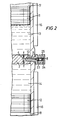
- Figure 1 represents a sectional view of the sample receiving and mixing device and Figure 2 shows an enlarged section of the sample outlet arrangement.
- the device has a cylindrical chamber (1) provided with a centrally located fixed, transverse baffle (2) having ports (3) and (4) and being held in position by spigots (7) and (10).
- Port (3) is connected to sample inlet (5) regulated by a needle valve (26) through channel (6) in the spigot (7) and port (4) is connected to sample outlet (8) via channel (9) in spigot (10).
- Two pistons (11) and (12) are disposed on either side of the baffle (2) defining therewith sub-chambers (13) and (14) respectively.
- the pistons are provided with magnetic monitors (15) and movement of the piston is detected by an external magnetic ladder indicator (16) responsive to the impulses generated by the monitors (15).
- the sample outlet (8) is closed by safety cap (25) and a sample of "live" crude oil is introduced into the sub-chambers by connecting the sample inlet (5) directly to the crude oil source.
- the piston (12) Upon introducing the sample into the sub-chambers and by maintaining a differential pressure in the two pistons through the gas inlets, the piston (12) is caused to move away from the baffle (2).
- the piston (12) reaches the end of its travel by abutting against the end of the chamber, the other piston (11) begins to move away from the baffle thereby indicating that the first sub-chamber (14) has received a full quota of the sample.
- the sample inlet is then closed and increased gas pressure is applied on the piston (12) furthest from the baffle (2) causing the sample to flow into the opposing sub-chamber (13) through the baffle ports (3) and (4).
- the applied pressure on the piston (12) is maintained until piston (11) has reached the end of its travel on the opposite side. Thereafter the applied pressure on the piston (12) is withdrawn and pressure applied on piston (11) thereby reversing the process and causing the sample to flow back into sub-chamber (14).
- the process is repeated several times until thorough mixing and homogeneity is achieved.
- the sample outlet (5) is opened by first removing the safety cap (25) and then introducing a syringe (not shown) through the septum (23) to withdraw an aliquot of the sample for analysis.
- the advantage of this process is that the continuous movement of the pistons need not be stopped during the withdrawal of the sample thereby ensuring thorough mixing until the moment of sampling.
- the design is such that there is no dynamic seal liable to allow leakage from the chamber and the sample, once trapped, cannot accidentally escape.
- the sliding action of the piston also ensures that the cylindrical walls are scraped clean of any component of the mixture, especially oil/water mixture, which might otherwise not be removed by rapid fluid motion.
- a sample of the inert gas can be analysed for hydrocarbon gases and an appropriate correction made. This would be an abnormal occurrence but serves to demonstrate the double security of the design.
Landscapes
- Geology (AREA)
- Mining & Mineral Resources (AREA)
- Chemical & Material Sciences (AREA)
- Engineering & Computer Science (AREA)
- Life Sciences & Earth Sciences (AREA)
- Physics & Mathematics (AREA)
- Dispersion Chemistry (AREA)
- Environmental & Geological Engineering (AREA)
- Chemical Kinetics & Catalysis (AREA)
- Fluid Mechanics (AREA)
- General Life Sciences & Earth Sciences (AREA)
- Geochemistry & Mineralogy (AREA)
- Sampling And Sample Adjustment (AREA)
- Investigating Or Analysing Biological Materials (AREA)
- Details Of Rigid Or Semi-Rigid Containers (AREA)
- Mixers With Rotating Receptacles And Mixers With Vibration Mechanisms (AREA)
Applications Claiming Priority (2)
| Application Number | Priority Date | Filing Date | Title |
|---|---|---|---|
| GB8212184 | 1982-04-27 | ||
| GB8212184 | 1982-04-27 |
Publications (2)
| Publication Number | Publication Date |
|---|---|
| EP0092975A1 true EP0092975A1 (fr) | 1983-11-02 |
| EP0092975B1 EP0092975B1 (fr) | 1987-01-14 |
Family
ID=10530003
Family Applications (1)
| Application Number | Title | Priority Date | Filing Date |
|---|---|---|---|
| EP83302261A Expired EP0092975B1 (fr) | 1982-04-27 | 1983-04-21 | Dispositif pour recevoir et mélanger des échantillons |
Country Status (6)
| Country | Link |
|---|---|
| EP (1) | EP0092975B1 (fr) |
| JP (1) | JPS593239A (fr) |
| DE (1) | DE3369089D1 (fr) |
| DK (1) | DK178383A (fr) |
| FI (1) | FI831441A7 (fr) |
| NO (1) | NO831468L (fr) |
Cited By (8)
| Publication number | Priority date | Publication date | Assignee | Title |
|---|---|---|---|---|
| EP0681863A3 (fr) * | 1994-05-10 | 1996-02-21 | Collagen Corp | Appareil et procédé pour mélanger des matériaux dans un environnement stérile. |
| WO2000058604A1 (fr) * | 1999-03-30 | 2000-10-05 | Den Norske Stats Oljeselskap A.S | Procede et systeme permettant de tester un trou de forage au moyen d'un bouchon mobile |
| NO20041135L (no) * | 2001-09-19 | 2004-05-18 | Baker Hughes Inc | En faset provetakninsmekanisme og prosedyre, med dobbelt stempel. |
| WO2007041660A1 (fr) * | 2005-10-06 | 2007-04-12 | Sgs Societe Generale De Surveillance S.A. | Analyse de la composition de phases gazeuses et liquides separees a l'aide d'un chromatographe en phase gazeuse |
| US8966969B2 (en) | 2010-07-19 | 2015-03-03 | Sgs North America Inc. | Automated analysis of pressurized reservoir fluids |
| US8991233B2 (en) | 2011-04-28 | 2015-03-31 | Sgs North America Inc. | Analysis of pressurized reservoir fluids |
| CN111347577A (zh) * | 2020-03-23 | 2020-06-30 | 杭州酬催科技有限公司 | 一种基于往复挤压原理的新材料混合装置 |
| CN111781019A (zh) * | 2020-07-03 | 2020-10-16 | 中国海洋石油集团有限公司 | 一种泵抽模块和流体取样方法 |
Families Citing this family (3)
| Publication number | Priority date | Publication date | Assignee | Title |
|---|---|---|---|---|
| JPS62136286A (ja) * | 1985-12-10 | 1987-06-19 | Kaiyo Kogyo Kk | 水中における薬剤混合方法および装置 |
| FR3046358B1 (fr) * | 2016-01-05 | 2020-12-04 | Ac&B | Procede et dispositif pour le melange de composants pour la fabrication d'un produit personnalise |
| CN110271748B (zh) * | 2019-06-24 | 2020-09-11 | 杨胜杰 | 一种海底沉积物多层保真储存取样设备 |
Citations (3)
| Publication number | Priority date | Publication date | Assignee | Title |
|---|---|---|---|---|
| FR2152452A1 (en) * | 1971-09-10 | 1973-04-27 | Merlin Gerin | Resin mixer dispenser unit - using twin adjustable throw pistons for a controlled volume discharge |
| FR2172334A1 (fr) * | 1972-02-18 | 1973-09-28 | Hurlimann Hans | |
| FR2447260A1 (fr) * | 1979-01-26 | 1980-08-22 | Euro Linea Snc Di Colombo Et C | Methode pour melanger au moins deux liquides et les envoyer dans un moule de mise en forme |
-
1983
- 1983-04-21 DE DE8383302261T patent/DE3369089D1/de not_active Expired
- 1983-04-21 EP EP83302261A patent/EP0092975B1/fr not_active Expired
- 1983-04-22 DK DK178383A patent/DK178383A/da not_active Application Discontinuation
- 1983-04-26 NO NO831468A patent/NO831468L/no unknown
- 1983-04-27 JP JP58074855A patent/JPS593239A/ja active Pending
- 1983-04-27 FI FI831441A patent/FI831441A7/fi not_active Application Discontinuation
Patent Citations (3)
| Publication number | Priority date | Publication date | Assignee | Title |
|---|---|---|---|---|
| FR2152452A1 (en) * | 1971-09-10 | 1973-04-27 | Merlin Gerin | Resin mixer dispenser unit - using twin adjustable throw pistons for a controlled volume discharge |
| FR2172334A1 (fr) * | 1972-02-18 | 1973-09-28 | Hurlimann Hans | |
| FR2447260A1 (fr) * | 1979-01-26 | 1980-08-22 | Euro Linea Snc Di Colombo Et C | Methode pour melanger au moins deux liquides et les envoyer dans un moule de mise en forme |
Cited By (19)
| Publication number | Priority date | Publication date | Assignee | Title |
|---|---|---|---|---|
| EP0681863A3 (fr) * | 1994-05-10 | 1996-02-21 | Collagen Corp | Appareil et procédé pour mélanger des matériaux dans un environnement stérile. |
| US5823671A (en) * | 1994-05-10 | 1998-10-20 | Collagen Corporation | Apparatus and method of mixing materials in a sterile environment |
| WO2000058604A1 (fr) * | 1999-03-30 | 2000-10-05 | Den Norske Stats Oljeselskap A.S | Procede et systeme permettant de tester un trou de forage au moyen d'un bouchon mobile |
| US6631763B1 (en) | 1999-03-30 | 2003-10-14 | Den Norske Stats Oljeselskap A.S. | Method and system for testing a borehole by the use of a movable plug |
| AU771007B2 (en) * | 1999-03-30 | 2004-03-11 | Equinor Energy As | Method and system for testing a borehole by the use of a movable plug |
| US7246664B2 (en) | 2001-09-19 | 2007-07-24 | Baker Hughes Incorporated | Dual piston, single phase sampling mechanism and procedure |
| US7621325B2 (en) | 2001-09-19 | 2009-11-24 | Baker Hughes Incorporated | Dual piston, single phase sampling mechanism and procedure |
| NO341415B1 (no) * | 2001-09-19 | 2017-10-30 | Baker Hughes A Ge Co Llc | Beholder og fremgangsmåte for å opprettholde faseintegriteten til en fluid |
| NO20041135L (no) * | 2001-09-19 | 2004-05-18 | Baker Hughes Inc | En faset provetakninsmekanisme og prosedyre, med dobbelt stempel. |
| EP1427912A4 (fr) * | 2001-09-19 | 2005-11-02 | Baker Hughes Inc | Procede et mecanisme d'echantillonnage monophasique a double piston |
| GB2447156A (en) * | 2005-10-06 | 2008-09-03 | Sgs Soc Gen De Surveillance Sa | Composition analysis of separated vapor and liquid phases using a gas chromatograph |
| US7467540B2 (en) | 2005-10-06 | 2008-12-23 | Sgs Societe Generale De Surveillance S.A. | Analysis systems and methods |
| GB2447156B (en) * | 2005-10-06 | 2011-02-16 | Sgs Soc Gen De Surveillance Sa | Compositional analysis of separated vapor and liquid phases using a gas chromatograph |
| WO2007041660A1 (fr) * | 2005-10-06 | 2007-04-12 | Sgs Societe Generale De Surveillance S.A. | Analyse de la composition de phases gazeuses et liquides separees a l'aide d'un chromatographe en phase gazeuse |
| US8966969B2 (en) | 2010-07-19 | 2015-03-03 | Sgs North America Inc. | Automated analysis of pressurized reservoir fluids |
| US8991233B2 (en) | 2011-04-28 | 2015-03-31 | Sgs North America Inc. | Analysis of pressurized reservoir fluids |
| CN111347577A (zh) * | 2020-03-23 | 2020-06-30 | 杭州酬催科技有限公司 | 一种基于往复挤压原理的新材料混合装置 |
| CN111347577B (zh) * | 2020-03-23 | 2022-01-11 | 株洲市圣翰有色焊材有限公司 | 一种基于往复挤压原理的新材料混合装置 |
| CN111781019A (zh) * | 2020-07-03 | 2020-10-16 | 中国海洋石油集团有限公司 | 一种泵抽模块和流体取样方法 |
Also Published As
| Publication number | Publication date |
|---|---|
| DK178383D0 (da) | 1983-04-22 |
| DK178383A (da) | 1983-10-28 |
| EP0092975B1 (fr) | 1987-01-14 |
| FI831441L (fi) | 1983-10-28 |
| NO831468L (no) | 1983-10-28 |
| FI831441A7 (fi) | 1983-10-28 |
| DE3369089D1 (en) | 1987-02-19 |
| FI831441A0 (fi) | 1983-04-27 |
| JPS593239A (ja) | 1984-01-09 |
Similar Documents
| Publication | Publication Date | Title |
|---|---|---|
| EP0092975B1 (fr) | Dispositif pour recevoir et mélanger des échantillons | |
| CA1146773A (fr) | Dispositif d'echantillonnage de fluide | |
| US6296769B1 (en) | Multi-chambered supercritical fluid extraction cartridge and processes using it | |
| US2994224A (en) | Fluid sampler | |
| US3567389A (en) | Fluid transfer valve structure | |
| US2842958A (en) | Apparatus for measuring flow characteristics of porous specimens by displacement | |
| DE69026364T2 (de) | Verfahren und Vorrichtung zur Auswertung der Permeabilität eines Körpers und ihre Verwendung in der Auswertung der Dysmigration | |
| US6148914A (en) | Sampling hydrocarbons in a well using a flexible bag | |
| US11143639B2 (en) | Integrated column and detector in a module for liquid chromatography | |
| US3793888A (en) | Cell for collecting and mixing fluids | |
| DE19915853A1 (de) | Pumpensystem zum Fördern von kryogenen Flüssigkeiten | |
| US4541452A (en) | Solvent pressurization system | |
| US4949858A (en) | Sample bottle and cap therefor | |
| US20200217768A1 (en) | Screening demulsifiers for crude live oil-water emulsions | |
| US3930403A (en) | Piston assembly | |
| DE1023597B (de) | Mischvorrichtung fuer verschiedene Fluessigkeiten bzw. Fluessigkeiten mit Gasen | |
| US4726238A (en) | Micro sampling valve for high pressure and temperature samples | |
| US5277252A (en) | Sampling tool for obtaining samples of fluids present in a well | |
| US3401802A (en) | Filter press | |
| US3371786A (en) | Filter press | |
| DE102007032761A1 (de) | Prüfvorrichtung und Verfahren zur Prüfung einer für eine Tieftemperaturanwendung vorgesehenen Dichtung | |
| RU2058544C1 (ru) | Устройство для определения концентрации растворенных газов в жидкостях | |
| GB2264172A (en) | Sampling bottle | |
| US3030801A (en) | Method for permeability measurements | |
| DE2521473C3 (de) | Lecküberwachungsvorrichtung |
Legal Events
| Date | Code | Title | Description |
|---|---|---|---|
| PUAI | Public reference made under article 153(3) epc to a published international application that has entered the european phase |
Free format text: ORIGINAL CODE: 0009012 |
|
| AK | Designated contracting states |
Designated state(s): BE DE FR GB IT NL SE |
|
| 17P | Request for examination filed |
Effective date: 19840416 |
|
| GRAA | (expected) grant |
Free format text: ORIGINAL CODE: 0009210 |
|
| AK | Designated contracting states |
Kind code of ref document: B1 Designated state(s): BE DE FR GB IT NL SE |
|
| PG25 | Lapsed in a contracting state [announced via postgrant information from national office to epo] |
Ref country code: NL Effective date: 19870114 Ref country code: IT Free format text: LAPSE BECAUSE OF FAILURE TO SUBMIT A TRANSLATION OF THE DESCRIPTION OR TO PAY THE FEE WITHIN THE PRESCRIBED TIME-LIMIT;WARNING: LAPSES OF ITALIAN PATENTS WITH EFFECTIVE DATE BEFORE 2007 MAY HAVE OCCURRED AT ANY TIME BEFORE 2007. THE CORRECT EFFECTIVE DATE MAY BE DIFFERENT FROM THE ONE RECORDED. Effective date: 19870114 Ref country code: FR Free format text: THE PATENT HAS BEEN ANNULLED BY A DECISION OF A NATIONAL AUTHORITY Effective date: 19870114 Ref country code: BE Effective date: 19870114 |
|
| PG25 | Lapsed in a contracting state [announced via postgrant information from national office to epo] |
Ref country code: SE Effective date: 19870131 |
|
| REF | Corresponds to: |
Ref document number: 3369089 Country of ref document: DE Date of ref document: 19870219 |
|
| EN | Fr: translation not filed | ||
| NLV1 | Nl: lapsed or annulled due to failure to fulfill the requirements of art. 29p and 29m of the patents act | ||
| PLBE | No opposition filed within time limit |
Free format text: ORIGINAL CODE: 0009261 |
|
| STAA | Information on the status of an ep patent application or granted ep patent |
Free format text: STATUS: NO OPPOSITION FILED WITHIN TIME LIMIT |
|
| 26N | No opposition filed | ||
| PG25 | Lapsed in a contracting state [announced via postgrant information from national office to epo] |
Ref country code: DE Effective date: 19880101 |
|
| REG | Reference to a national code |
Ref country code: GB Ref legal event code: IF02 |
|
| PGFP | Annual fee paid to national office [announced via postgrant information from national office to epo] |
Ref country code: GB Payment date: 20020313 Year of fee payment: 20 |
|
| PG25 | Lapsed in a contracting state [announced via postgrant information from national office to epo] |
Ref country code: GB Free format text: LAPSE BECAUSE OF EXPIRATION OF PROTECTION Effective date: 20030420 |
|
| REG | Reference to a national code |
Ref country code: GB Ref legal event code: PE20 |