EP0092983B1 - Rührgerät für eine Metallschmelze - Google Patents
Rührgerät für eine Metallschmelze Download PDFInfo
- Publication number
- EP0092983B1 EP0092983B1 EP83302281A EP83302281A EP0092983B1 EP 0092983 B1 EP0092983 B1 EP 0092983B1 EP 83302281 A EP83302281 A EP 83302281A EP 83302281 A EP83302281 A EP 83302281A EP 0092983 B1 EP0092983 B1 EP 0092983B1
- Authority
- EP
- European Patent Office
- Prior art keywords
- riser
- molten metal
- melting furnace
- changeover valve
- valve
- Prior art date
- Legal status (The legal status is an assumption and is not a legal conclusion. Google has not performed a legal analysis and makes no representation as to the accuracy of the status listed.)
- Expired
Links
Images




Classifications
-
- F—MECHANICAL ENGINEERING; LIGHTING; HEATING; WEAPONS; BLASTING
- F27—FURNACES; KILNS; OVENS; RETORTS
- F27D—DETAILS OR ACCESSORIES OF FURNACES, KILNS, OVENS OR RETORTS, IN SO FAR AS THEY ARE OF KINDS OCCURRING IN MORE THAN ONE KIND OF FURNACE
- F27D27/00—Stirring devices for molten material
-
- C—CHEMISTRY; METALLURGY
- C21—METALLURGY OF IRON
- C21C—PROCESSING OF PIG-IRON, e.g. REFINING, MANUFACTURE OF WROUGHT-IRON OR STEEL; TREATMENT IN MOLTEN STATE OF FERROUS ALLOYS
- C21C7/00—Treating molten ferrous alloys, e.g. steel, not covered by groups C21C1/00 - C21C5/00
-
- B—PERFORMING OPERATIONS; TRANSPORTING
- B01—PHYSICAL OR CHEMICAL PROCESSES OR APPARATUS IN GENERAL
- B01F—MIXING, e.g. DISSOLVING, EMULSIFYING OR DISPERSING
- B01F25/00—Flow mixers; Mixers for falling materials, e.g. solid particles
- B01F25/50—Circulation mixers, e.g. wherein at least part of the mixture is discharged from and reintroduced into a receptacle
-
- B—PERFORMING OPERATIONS; TRANSPORTING
- B01—PHYSICAL OR CHEMICAL PROCESSES OR APPARATUS IN GENERAL
- B01F—MIXING, e.g. DISSOLVING, EMULSIFYING OR DISPERSING
- B01F31/00—Mixers with shaking, oscillating, or vibrating mechanisms
- B01F31/65—Mixers with shaking, oscillating, or vibrating mechanisms the materials to be mixed being directly submitted to a pulsating movement, e.g. by means of an oscillating piston or air column
-
- B—PERFORMING OPERATIONS; TRANSPORTING
- B01—PHYSICAL OR CHEMICAL PROCESSES OR APPARATUS IN GENERAL
- B01F—MIXING, e.g. DISSOLVING, EMULSIFYING OR DISPERSING
- B01F31/00—Mixers with shaking, oscillating, or vibrating mechanisms
- B01F31/65—Mixers with shaking, oscillating, or vibrating mechanisms the materials to be mixed being directly submitted to a pulsating movement, e.g. by means of an oscillating piston or air column
- B01F31/651—Mixing by successively aspirating a part of the mixture in a conduit, e.g. a piston, and reinjecting it through the same conduit into the receptacle
-
- C—CHEMISTRY; METALLURGY
- C22—METALLURGY; FERROUS OR NON-FERROUS ALLOYS; TREATMENT OF ALLOYS OR NON-FERROUS METALS
- C22B—PRODUCTION AND REFINING OF METALS; PRETREATMENT OF RAW MATERIALS
- C22B21/00—Obtaining aluminium
- C22B21/0084—Obtaining aluminium melting and handling molten aluminium
-
- C—CHEMISTRY; METALLURGY
- C22—METALLURGY; FERROUS OR NON-FERROUS ALLOYS; TREATMENT OF ALLOYS OR NON-FERROUS METALS
- C22B—PRODUCTION AND REFINING OF METALS; PRETREATMENT OF RAW MATERIALS
- C22B9/00—General processes of refining or remelting of metals; Apparatus for electroslag or arc remelting of metals
-
- C—CHEMISTRY; METALLURGY
- C22—METALLURGY; FERROUS OR NON-FERROUS ALLOYS; TREATMENT OF ALLOYS OR NON-FERROUS METALS
- C22B—PRODUCTION AND REFINING OF METALS; PRETREATMENT OF RAW MATERIALS
- C22B9/00—General processes of refining or remelting of metals; Apparatus for electroslag or arc remelting of metals
- C22B9/02—Refining by liquating, filtering, centrifuging, distilling, or supersonic wave action including acoustic waves
-
- F—MECHANICAL ENGINEERING; LIGHTING; HEATING; WEAPONS; BLASTING
- F27—FURNACES; KILNS; OVENS; RETORTS
- F27D—DETAILS OR ACCESSORIES OF FURNACES, KILNS, OVENS OR RETORTS, IN SO FAR AS THEY ARE OF KINDS OCCURRING IN MORE THAN ONE KIND OF FURNACE
- F27D17/00—Arrangements for using waste heat; Arrangements for using, or disposing of, waste gases
- F27D17/30—Arrangements for extraction or collection of waste gases; Hoods therefor
-
- F—MECHANICAL ENGINEERING; LIGHTING; HEATING; WEAPONS; BLASTING
- F27—FURNACES; KILNS; OVENS; RETORTS
- F27D—DETAILS OR ACCESSORIES OF FURNACES, KILNS, OVENS OR RETORTS, IN SO FAR AS THEY ARE OF KINDS OCCURRING IN MORE THAN ONE KIND OF FURNACE
- F27D27/00—Stirring devices for molten material
- F27D27/005—Pumps
-
- F—MECHANICAL ENGINEERING; LIGHTING; HEATING; WEAPONS; BLASTING
- F27—FURNACES; KILNS; OVENS; RETORTS
- F27D—DETAILS OR ACCESSORIES OF FURNACES, KILNS, OVENS OR RETORTS, IN SO FAR AS THEY ARE OF KINDS OCCURRING IN MORE THAN ONE KIND OF FURNACE
- F27D27/00—Stirring devices for molten material
- F27D27/005—Pumps
- F27D27/007—Pulsating pumps
-
- Y—GENERAL TAGGING OF NEW TECHNOLOGICAL DEVELOPMENTS; GENERAL TAGGING OF CROSS-SECTIONAL TECHNOLOGIES SPANNING OVER SEVERAL SECTIONS OF THE IPC; TECHNICAL SUBJECTS COVERED BY FORMER USPC CROSS-REFERENCE ART COLLECTIONS [XRACs] AND DIGESTS
- Y02—TECHNOLOGIES OR APPLICATIONS FOR MITIGATION OR ADAPTATION AGAINST CLIMATE CHANGE
- Y02P—CLIMATE CHANGE MITIGATION TECHNOLOGIES IN THE PRODUCTION OR PROCESSING OF GOODS
- Y02P10/00—Technologies related to metal processing
- Y02P10/20—Recycling
Definitions
- the present invention relates to molten metal stirring apparatus to stir molten metal by sucking the molten metal into a riser linked to a melting furnace beneath the surface of molten metal in the melting furnace, and returning the molten metal in the riser into the melting furnace.
- US-A-4 236 917 discloses stirring by providing a riser linked to the melting furnace beneath the surface of molten metal, the end of the riser being connected by a changeover valve to either a vacuum source or a source of gas under pressure.
- the molten metal is alternately drawn into the riser under the action of the vacuum, and expelled back into the furnace by the action of the pressurised gas.
- molten metal stirring apparatus for a melting furnace such apparatus including a riser opening into the melting furnace beneath level of the surface of molten metal in the melting furnace when the furnace is in use, a changeover valve connected to the upper end of the riser, and a vacuum source for applying reducing pressure inside the upper end of the riser connected to the changeover valve, characterised by duct means for leading exhaust gas from the melting furnace to the upper end of the riser, connected to the changeover valve, and an electric heater for heating the riser provided in the vicinity of the surface of the molten metal when sucked in the riser.
- the apparatus includes further heating means for heating the riser and located coaxially with and on the outer periphery of the riser below said electric heater.
- the inner wall of the riser is lined with silicon carbide refractories containing silicon nitride bonding or silicon oxynitride bonding, the deposit of molten metal on the riser is restricted, and the strength of riser, such as spalling resistance, may be improved.
- the changeover valve is operated by gas pressure, so that switching involving electric contacts as experienced in the prior art is not necessary, which facilitates maintenance.
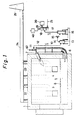
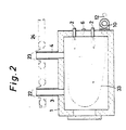
- Figure 1 is a vertical section of one of the embodiments of the present invention and Figure 2 is its horizontal section.
- a burner 2 is provided in a melting furnace 1.
- Ingot or scraps charged through the charge preheat chambers 3, 4 are melted as indicated by reference code 5.
- One of such molten metals 5 may be, for example, aluminum.
- the molten metal 5 is taken out to the outside from an outlet 6.
- the protective tank 13 is intended to prevent the molten metal 5 sucked in the riser 10 from partly flowing into the pipeline 12 to run into the pipe- line 14 and subsequent units so as to protect the subsequent units.
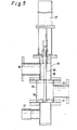
- Figure 3 is a magnified section of the riser 10.
- An inlet 68 of molten metal into the riser 10 of melting furnace 1 is shaped in a circular form, but it it not limited to circular form. For example, it may be shaped in an oval form extending in the horizontal direction (the direction vertical to the sheet surface of Figure 3) or other form, provided that it be shaped in circular form in the bottom 69 of the riser 10.
- the inner wall of the riser 10 is lined with silicon carbide refractories 65 containing silicon nitride bonding or silicon oxynitride bonding.
- the chemical composition of the silicon carbide refractories 65 is, for example, silicon carbide 78.0 wt.%, silicon dioxide 3.0 wt.%, ferric oxide 0.4 wt.%, and sum of silicon nitride (Si 3 N 4 ) and silicon oxynitride (Si 2 0N 2 ) 18.0 wt.%.
- the outer periphery of the silicon carbide refractories is covered, for example, with ceramic heat insulating material 28.
- An electric heater 31 is provided at the upper end of the riser 10 on the outside of the heat insulating material 28.
- This electric heater 31 is electrically energized to heat the inner temperature of the heat insulating material 28 surrounded with the electric heater 31 to temperatures higher than the melting point of the molten metal, for example, 650 to 750°C. This prevents solidification of the molten metal in the vicinity of the surface 32 where the molten metal sucked in the riser 10 reaches.
- another electric heater 66 is provided coaxially with the riser and along its entire circumference and overall length. This electric heater 66 is similarly energized with electric power to heat the inner parts of the heat insulating material 28 surrounded by the electric heater 66 to temperatures higher than the melting point of the molten metal. Accordingly, solidification of the molten metal in the riser 10 is prevented.
- the outer surfaces of the electric heaters 31 and 66 are covered with insulators 29, which are further covered with outer skin 30 made of iron or similar material.
- the insulators 29 may be, for example, castable refractories made of alumina cement.
- the constitution may be simplified.
- the molten metal in the riser returns to the melting furnace 1, the molten metal in the melting furnace is stirred by indicated by arrow 33 in Figure 2.
- the riser 10 is provided near the corner of melting furnace 1, but it may be located in other position.
- the oxygen concentration of the exhaust gas is low, and oxidation of the molten metal sucked in the riser 10 is inhibited. It also contributes to restriction of clogging due to oxides in the riser 10.
- FIG. 4 is a magnified section of riser 10 showing other embodiment, wherein the parts corresponding to those used in the preceding embodiment are given the same reference codes.
- the inside of the riser 10 in its radial direction is composed of heat insulating materials 28, which are externally covered with insulators 29.
- the insulators 29 are further covered with iron or other outer skin 30.
- an electric heater 31 is provided in a way to surround the heat insulating materials 28.
- This electric heater 31 is electrically energized to heat the inner parts of the heat insulating materials 28 surrounded by the electric heater 31 to temperatures higher than the melting point of the molten metal, for example 650 to 750°C.
- solidification of the molten metal is prevented in the vicinity of the surface 32 where the molten metal sucked in the riser 10 reaches. Hence, clogging in the riser 10 is prevented.
- the electric heater 66 is provided coaxially with the riser 10 and along its entire circumference and overall length, beneath the position where the electric heater 31 is provided at the upper end of the riser 10, in a manner to surround the heat insulating materials 28.-In another embodiment, the electric heater 66 may be partially provided coaxially with the riser 10 and externally surrounding it.
- the heating means consisted of electric heaters 31 and 66 provided coaxially with the riser and along its entire circumference and overall length.
- the heating means may be so constituted to supply high temperature gas higher than the melting point of the molten metal beneath the electric heater, coaxially with the riser 10 and along its entire circumference and overall length, in place of electric heater 66.
- Figure 6 is a pneumatic circuit diagram of control unit 40 for controlling the pneumatic cylinder 37 for driving the three-way changeover valve 18.
- the e air pressure from the air pressure source 41 is applied from the pipeline 42 to operating valves 43, 44.
- the operating valve 43 is connected to an operating valve 45.
- the operating valve 44 is connected to an operating valve 46.
- the air pressure from the operating valve 45 is applied to a timer circuit 47.
- the air pressure from the timer circuit 47 and operating valve 46 is applied from the OR circuit 48 and pilot pipeline 52 as the pilot pressure of two-position changeover valve 49 of spring offset type pilot operating system.
- the air pressure from the air pressure source 41 is changed over and given to either chamber 50 or 51 of the pneumatic cylinder 37 by way of changeover valve 49 from the pipeline 61.
- the operating valves 43, 45 are operated in communicated state.
- the timer circuit 47 releases supply of air pressure into pilot pipeline 52 for a first time W1 as shown in Figure 9, and supplies air pressure to the pilot pipe- line 52 for the next time W2.
- the chamber 50 in the pneumatic cylinder 37 is raised to high pressure for time W1, and the pipelines 17 and 19 are communicated with each other, and the molten metal 5 is sucked into the riser 10.
- the chamber 51 in the pneumatic cylinder 37 is raised to high pressure, and the pipelines 17 and 21 are communicated with each other, thereby supplying exhaust gas into the riser 10.
- the duration of W1 is4to 10 seconds, and that of W2 2 to 4 seconds.
- the on-delay circuit 53 contained in thetimercir- cuit 47 operates as shown in Figure 7.
- This on-delay circuit 53 communicates ports 53b and 53c after lapse of time T1 as shown in Figure 7 (2) when an air pressure indicated by Figure 7 (1) is given to pilot port 53a.
- an off-delay circuit 54 disconnects ports 54b, 54c after lapse of timer T2 as shown in Figure 8 (2) when an air pressure indicated by Figure 8 (1) is given to pilot port 54a.
Landscapes
- Chemical & Material Sciences (AREA)
- Engineering & Computer Science (AREA)
- Mechanical Engineering (AREA)
- Chemical Kinetics & Catalysis (AREA)
- Materials Engineering (AREA)
- Metallurgy (AREA)
- Organic Chemistry (AREA)
- Manufacturing & Machinery (AREA)
- Physics & Mathematics (AREA)
- Acoustics & Sound (AREA)
- General Engineering & Computer Science (AREA)
- Waste-Gas Treatment And Other Accessory Devices For Furnaces (AREA)
- Vertical, Hearth, Or Arc Furnaces (AREA)
Claims (4)
Applications Claiming Priority (8)
| Application Number | Priority Date | Filing Date | Title |
|---|---|---|---|
| JP69310/82 | 1982-04-23 | ||
| JP69309/82 | 1982-04-23 | ||
| JP6930982A JPS58185729A (ja) | 1982-04-23 | 1982-04-23 | 溶融金属の撹「はん」装置 |
| JP6931082A JPS58185730A (ja) | 1982-04-23 | 1982-04-23 | 溶融金属の撹「はん」装置のための制御装置 |
| JP57123645A JPS5913016A (ja) | 1982-07-14 | 1982-07-14 | 溶融金属の撹拌装置 |
| JP123644/82 | 1982-07-14 | ||
| JP57123644A JPS5913015A (ja) | 1982-07-14 | 1982-07-14 | 溶融金属の撹拌装置 |
| JP123645/82 | 1982-07-14 |
Publications (2)
| Publication Number | Publication Date |
|---|---|
| EP0092983A1 EP0092983A1 (de) | 1983-11-02 |
| EP0092983B1 true EP0092983B1 (de) | 1987-04-29 |
Family
ID=27465106
Family Applications (1)
| Application Number | Title | Priority Date | Filing Date |
|---|---|---|---|
| EP83302281A Expired EP0092983B1 (de) | 1982-04-23 | 1983-04-21 | Rührgerät für eine Metallschmelze |
Country Status (5)
| Country | Link |
|---|---|
| US (1) | US4463935A (de) |
| EP (1) | EP0092983B1 (de) |
| KR (1) | KR850000928B1 (de) |
| CA (1) | CA1220025A (de) |
| DE (1) | DE3371226D1 (de) |
Families Citing this family (8)
| Publication number | Priority date | Publication date | Assignee | Title |
|---|---|---|---|---|
| FR2570618B1 (fr) * | 1984-09-25 | 1987-01-09 | Lemarre Anicet | Dispositif pour homogeneiser des produits fluides qui ont naturellement tendance au demelange et applications notamment a la methanisation |
| DE3639335A1 (de) * | 1986-11-18 | 1988-05-26 | Bayer Ag | Gegenueber metall- und salzschmelzen resistente werkstoffe, ihre herstellung und deren verwendung |
| GB2220974B (en) * | 1988-05-04 | 1992-11-18 | Apv Uk | Aseptic processing system |
| CA1330486C (en) * | 1988-05-20 | 1994-07-05 | Marc-Andre Thibault | Apparatus for stirring molten metal |
| US5160479A (en) * | 1988-12-15 | 1992-11-03 | Sumitomo Light Metal Industries, Ltd. | Molten metal stirring device |
| CA2029680A1 (en) * | 1990-11-09 | 1992-05-10 | Francois Tremblay | Jet flow device for injecting gas into molten metal |
| AU643644B2 (en) * | 1991-07-05 | 1993-11-18 | Sumitomo Light Metal Industries, Ltd. | Molten metal stirring device |
| CN108731489B (zh) * | 2018-05-28 | 2019-09-06 | 遵义中铂硬质合金有限责任公司 | 烧结炉余热回收装置 |
Family Cites Families (9)
| Publication number | Priority date | Publication date | Assignee | Title |
|---|---|---|---|---|
| DE1113577B (de) * | 1958-03-28 | 1961-09-07 | Internat Alloys Ltd | Einrichtung fuer die kontinuierliche Vakuumbehandlung von Metallen |
| CH436362A (de) * | 1965-04-02 | 1967-05-31 | F Erdelyi Frank | Verfahren zum Reinigen von Metall-, insbesondere Stahl-Schmelzen und zum Vergiessen derartiger Schmelzen und Vorrichtung zur Ausführung des Verfahrens |
| US3490896A (en) * | 1966-09-07 | 1970-01-20 | Kaiser Aluminium Chem Corp | Process for improving mixing efficiency |
| US4008884A (en) * | 1976-06-17 | 1977-02-22 | Alcan Research And Development Limited | Stirring molten metal |
| US4236917A (en) * | 1978-07-21 | 1980-12-02 | Dolzhenkov Boris S | Method of gas-dynamic stirring of liquid molten metals and apparatus for performing same |
| US4328958A (en) * | 1978-08-07 | 1982-05-11 | Dolzhenkov Boris S | Apparatus for stirring molten metal in container |
| US4235626A (en) * | 1978-12-19 | 1980-11-25 | Dolzhenkov Boris S | Method and apparatus for stirring molten metal |
| GB2039761B (en) * | 1979-01-11 | 1982-12-15 | Dolzhenkov B | Method and apparatus for stirring molten metal |
| US4355789A (en) * | 1981-01-15 | 1982-10-26 | Dolzhenkov Boris S | Gas pump for stirring molten metal |
-
1983
- 1983-04-19 KR KR1019830001653A patent/KR850000928B1/ko not_active Expired
- 1983-04-20 US US06/486,964 patent/US4463935A/en not_active Expired - Fee Related
- 1983-04-20 CA CA000426225A patent/CA1220025A/en not_active Expired
- 1983-04-21 DE DE8383302281T patent/DE3371226D1/de not_active Expired
- 1983-04-21 EP EP83302281A patent/EP0092983B1/de not_active Expired
Also Published As
| Publication number | Publication date |
|---|---|
| DE3371226D1 (en) | 1987-06-04 |
| US4463935A (en) | 1984-08-07 |
| KR840004454A (ko) | 1984-10-15 |
| KR850000928B1 (ko) | 1985-06-28 |
| EP0092983A1 (de) | 1983-11-02 |
| CA1220025A (en) | 1987-04-07 |
Similar Documents
| Publication | Publication Date | Title |
|---|---|---|
| EP0092983B1 (de) | Rührgerät für eine Metallschmelze | |
| CA2083919C (en) | Molten metal coveying means and method of conveying molten metal from one place to another in a metal-melting furnace | |
| AU763426B2 (en) | Metallurgical vessel comprising a tapping device and method for the controlled, slag-free extraction of molten metal from said vessel | |
| US20180345364A1 (en) | Slide closure on the spout of a metallurgical vessel | |
| US4460389A (en) | Device for filtering dust extracted from factory buildings | |
| EP0144559A1 (de) | Anlage zum Induktionserwärmen von geschmolzenem Metall | |
| EP1372891A1 (de) | Vorrichtung zum überführen flüssigen metalls aus einem sammelbehälter zu einem aufnahmebehälter | |
| EP0238884B1 (de) | Vorrichtung zum Halten und Raffinieren von Aluminiumschmelze | |
| US3533611A (en) | Furnace ventilation system | |
| US4483709A (en) | Steel production method | |
| JPH0127040Y2 (de) | ||
| JPS6359074B2 (de) | ||
| JP3125466B2 (ja) | 金属の精密鋳造方法および精密鋳造装置 | |
| US3603572A (en) | Method and apparatus for operating basic oxygen furnaces | |
| JP3120024B2 (ja) | フライアッシュの溶融処理装置 | |
| JPS58185730A (ja) | 溶融金属の撹「はん」装置のための制御装置 | |
| JPH0661610B2 (ja) | 加圧式注湯炉 | |
| WO1986004980A1 (en) | Apparatus and process for transferring a predetermined amount of liquid metal from a vessel containing a molten metal bath into a receiving container | |
| EP0068901A1 (de) | Ofen zum Schmelzen von Metallspänen | |
| JPS6339643B2 (de) | ||
| US5200135A (en) | Method to improve the service life of gas injection devices used to introduce a gas into molten metal | |
| JPH0618676Y2 (ja) | 取鍋集塵装置 | |
| JPS58185729A (ja) | 溶融金属の撹「はん」装置 | |
| JP2002234734A (ja) | ガラス溶融炉 | |
| RU15730U1 (ru) | Устройство для непрерывного выпуска чугуна из доменной печи |
Legal Events
| Date | Code | Title | Description |
|---|---|---|---|
| PUAI | Public reference made under article 153(3) epc to a published international application that has entered the european phase |
Free format text: ORIGINAL CODE: 0009012 |
|
| AK | Designated contracting states |
Kind code of ref document: A1 Designated state(s): DE FR GB IT NL |
|
| 17P | Request for examination filed |
Effective date: 19840121 |
|
| GRAA | (expected) grant |
Free format text: ORIGINAL CODE: 0009210 |
|
| AK | Designated contracting states |
Kind code of ref document: B1 Designated state(s): DE FR GB IT NL |
|
| REF | Corresponds to: |
Ref document number: 3371226 Country of ref document: DE Date of ref document: 19870604 |
|
| ET | Fr: translation filed | ||
| ITF | It: translation for a ep patent filed | ||
| PLBE | No opposition filed within time limit |
Free format text: ORIGINAL CODE: 0009261 |
|
| STAA | Information on the status of an ep patent application or granted ep patent |
Free format text: STATUS: NO OPPOSITION FILED WITHIN TIME LIMIT |
|
| 26N | No opposition filed | ||
| PG25 | Lapsed in a contracting state [announced via postgrant information from national office to epo] |
Ref country code: GB Effective date: 19880421 |
|
| PG25 | Lapsed in a contracting state [announced via postgrant information from national office to epo] |
Ref country code: NL Effective date: 19881101 |
|
| NLV4 | Nl: lapsed or anulled due to non-payment of the annual fee | ||
| GBPC | Gb: european patent ceased through non-payment of renewal fee | ||
| PG25 | Lapsed in a contracting state [announced via postgrant information from national office to epo] |
Ref country code: FR Free format text: LAPSE BECAUSE OF NON-PAYMENT OF DUE FEES Effective date: 19881229 |
|
| PG25 | Lapsed in a contracting state [announced via postgrant information from national office to epo] |
Ref country code: DE Effective date: 19890103 |
|
| REG | Reference to a national code |
Ref country code: FR Ref legal event code: ST |