EP0093016A1 - Igniteur à incandescence - Google Patents
Igniteur à incandescence Download PDFInfo
- Publication number
- EP0093016A1 EP0093016A1 EP83302373A EP83302373A EP0093016A1 EP 0093016 A1 EP0093016 A1 EP 0093016A1 EP 83302373 A EP83302373 A EP 83302373A EP 83302373 A EP83302373 A EP 83302373A EP 0093016 A1 EP0093016 A1 EP 0093016A1
- Authority
- EP
- European Patent Office
- Prior art keywords
- combustible mixture
- combustion chamber
- wire
- liquid fuel
- ignitor
- Prior art date
- Legal status (The legal status is an assumption and is not a legal conclusion. Google has not performed a legal analysis and makes no representation as to the accuracy of the status listed.)
- Withdrawn
Links
- 238000002485 combustion reaction Methods 0.000 claims abstract description 37
- 239000000203 mixture Substances 0.000 claims abstract description 31
- 239000007788 liquid Substances 0.000 claims abstract description 30
- 239000007921 spray Substances 0.000 claims abstract description 8
- 239000000295 fuel oil Substances 0.000 claims abstract description 4
- 239000000446 fuel Substances 0.000 claims description 48
- 238000010438 heat treatment Methods 0.000 claims description 12
- QVGXLLKOCUKJST-UHFFFAOYSA-N atomic oxygen Chemical compound [O] QVGXLLKOCUKJST-UHFFFAOYSA-N 0.000 claims description 7
- 229910052760 oxygen Inorganic materials 0.000 claims description 7
- 239000001301 oxygen Substances 0.000 claims description 7
- 239000007789 gas Substances 0.000 claims description 6
- 238000000034 method Methods 0.000 claims description 4
- 238000005507 spraying Methods 0.000 claims 2
- 230000000977 initiatory effect Effects 0.000 claims 1
- 239000003921 oil Substances 0.000 abstract description 12
- OKTJSMMVPCPJKN-UHFFFAOYSA-N Carbon Chemical compound [C] OKTJSMMVPCPJKN-UHFFFAOYSA-N 0.000 description 2
- 229910052799 carbon Inorganic materials 0.000 description 2
- 239000000567 combustion gas Substances 0.000 description 2
- 230000003628 erosive effect Effects 0.000 description 2
- 125000006850 spacer group Chemical group 0.000 description 2
- 229910001220 stainless steel Inorganic materials 0.000 description 2
- 239000010935 stainless steel Substances 0.000 description 2
- 238000000889 atomisation Methods 0.000 description 1
- VLYDPWNOCPZGEV-UHFFFAOYSA-M benzyl-dimethyl-[2-[2-[2-methyl-4-(2,4,4-trimethylpentan-2-yl)phenoxy]ethoxy]ethyl]azanium;chloride;hydrate Chemical compound O.[Cl-].CC1=CC(C(C)(C)CC(C)(C)C)=CC=C1OCCOCC[N+](C)(C)CC1=CC=CC=C1 VLYDPWNOCPZGEV-UHFFFAOYSA-M 0.000 description 1
- 238000001816 cooling Methods 0.000 description 1
- 238000012423 maintenance Methods 0.000 description 1
- 230000005019 pattern of movement Effects 0.000 description 1
Images
Classifications
-
- F—MECHANICAL ENGINEERING; LIGHTING; HEATING; WEAPONS; BLASTING
- F23—COMBUSTION APPARATUS; COMBUSTION PROCESSES
- F23Q—IGNITION; EXTINGUISHING-DEVICES
- F23Q7/00—Incandescent ignition; Igniters using electrically-produced heat, e.g. lighters for cigarettes; Electrically-heated glowing plugs
- F23Q7/06—Incandescent ignition; Igniters using electrically-produced heat, e.g. lighters for cigarettes; Electrically-heated glowing plugs structurally associated with fluid-fuel burners
- F23Q7/08—Incandescent ignition; Igniters using electrically-produced heat, e.g. lighters for cigarettes; Electrically-heated glowing plugs structurally associated with fluid-fuel burners for evaporating and igniting liquid fuel, e.g. in hurricane lanterns
-
- F—MECHANICAL ENGINEERING; LIGHTING; HEATING; WEAPONS; BLASTING
- F23—COMBUSTION APPARATUS; COMBUSTION PROCESSES
- F23C—METHODS OR APPARATUS FOR COMBUSTION USING FLUID FUEL OR SOLID FUEL SUSPENDED IN A CARRIER GAS OR AIR
- F23C6/00—Combustion apparatus characterised by the combination of two or more combustion chambers or combustion zones, e.g. for staged combustion
- F23C6/04—Combustion apparatus characterised by the combination of two or more combustion chambers or combustion zones, e.g. for staged combustion in series connection
- F23C6/045—Combustion apparatus characterised by the combination of two or more combustion chambers or combustion zones, e.g. for staged combustion in series connection with staged combustion in a single enclosure
-
- F—MECHANICAL ENGINEERING; LIGHTING; HEATING; WEAPONS; BLASTING
- F23—COMBUSTION APPARATUS; COMBUSTION PROCESSES
- F23C—METHODS OR APPARATUS FOR COMBUSTION USING FLUID FUEL OR SOLID FUEL SUSPENDED IN A CARRIER GAS OR AIR
- F23C7/00—Combustion apparatus characterised by arrangements for air supply
-
- F—MECHANICAL ENGINEERING; LIGHTING; HEATING; WEAPONS; BLASTING
- F23—COMBUSTION APPARATUS; COMBUSTION PROCESSES
- F23M—CASINGS, LININGS, WALLS OR DOORS SPECIALLY ADAPTED FOR COMBUSTION CHAMBERS, e.g. FIREBRIDGES; DEVICES FOR DEFLECTING AIR, FLAMES OR COMBUSTION PRODUCTS IN COMBUSTION CHAMBERS; SAFETY ARRANGEMENTS SPECIALLY ADAPTED FOR COMBUSTION APPARATUS; DETAILS OF COMBUSTION CHAMBERS, NOT OTHERWISE PROVIDED FOR
- F23M5/00—Casings; Linings; Walls
- F23M5/08—Cooling thereof; Tube walls
- F23M5/085—Cooling thereof; Tube walls using air or other gas as the cooling medium
Definitions
- the present invention relates to an incandescent ignitor for use in burners or combustors of liquid fuel and to a method of igniting a combustible mixture of liquid and oxygen.
- the ignitor must, of course, be sufficiently close, physically, to the combustible oil/air mixture to ignite the same yet when the ignitor is actually in the stream of oil injected into the combustor the ignitor can become fouled and its performance and reliability reduced.
- liquid fuel such as oil is injected by a nozzle in a spray causing atomization of the fuel and creating a combustible fuel/air mixture in certain zones of the combustion chamber.
- the difficulties with the existing spark or energy discharge type of ignitors are alleviated by providing an incandescent ignitor and a method of igniting a combustible fuel as claimed in the appended claims that are usable with a liquid-fuel combustor such as an oil-fired combustor.
- the incandescent ignitor-of the present invention is typically a low-voltage device (less than 250 volts) that provides a high temperature, i.e. about 1200°-2500°F and thereby creates a plume of extremely hot gas that causes the ignition of the combustible mixture of oil and air in the combustion chamber.
- a high resistance coil of heated wire in the ignitor is positioned sufficiently near the combustible mixture in the combustion chamber to ignite the same mixture by the hot plume of gas but the coil is kept away from the direct stream of the atomized oil as it is injected thereinto.
- the location of the ignitor is typically in a zone with a fairly stable, stoichiometric mixture of the oil and air in operation of the combustor. Protection against carbon build-up may be afforded both by the position of the ignitor with respect to the spray of 1iquid ⁇ oi1 and also by surrounding the heated wire of such ignitor with a cylindrical housing such that the plume of heated air is caused to pass from the heated wire of the ignitor out into the zone where the combustible mixture is present, thus causing ignition.
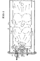
- a combustor 30 for use with a liquid fuel such as oil.
- the combustor 30 is preferably cylindrical in shape and includes an outer shell 32 generally constructed of 12 guage stainless steel.
- An outer shell 32 generally constructed of 12 guage stainless steel.
- a liner 34 constructed of relative thin (.050" thick stainless steel) and within which is contained or defined a primary combustion chamber or zone volume 36 and a secondary combustion chamber or zone 38 where the hot gases from primary combustion chamber 36 are mixed with secondary air to complete the combustion process.
- the air for the combustion taking place in primary combustion chamber 36 and for completion of combustion in secondary combustion chamber 38 is supplied by a fan, not shown, and air passes through the annular passage 40 between liner 34 and outer shell 32 and which flow of air serves to cool the liner 34 and outer shell 32. As noted in Fig.l, the air passes through the annular passage 40 in the direction of arrows 42.
- An end plate 44 closes off one end of the combustor 30 and is fitted into the ends of the liner 34 and the outer shell 32 to close the same.
- a nozzle holder 46 Centrally located through end plate 44 is fitted a nozzle holder 46 which, among other functions, channels air for determining the pattern of fuel distribution for liquid fuel injected by means of the fuel nozzle 48.
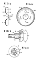
- the nozzle holder 46 is more fully shown in Figs.2 and 3 in cross section and end view, respectively, and generally comprises a body 50 having an opening 52, one end of which opening 52 opens into an angled opening 54 at an angle of approximately 90° about its central axis, as shown, and further comprises a plurality of radially oriented apertures 56 which open into the angled opening 54.
- a recess 58 is formed in body 50 in order to receive the fuel nozzle 48 (not shown in Figs. 4 and 5).
- the fuel nozzle 48 may be of conventional commercial design as supplied by the Delavan Corporation Nozzle Model No. 27710-1 and which is rated for a fuel consumption at 50 lbs/hr of JP4 fuel oil at a supply pressure of 100 psig.
- the particular fuel nozzle 48 is of a design that sprays out the atomized fuel oil on the shape of a holloq cone at a total angle of approximately 75° + 5° about its central axis. By passing air through the apertures 56, the liquid fuel is caused to swirl and produce a vortex flow in the primary combustion chamber 36.
- the outer surface 57 of the nozzle holder 46 is angled with respect to its central axis at approximately 30° thereto, or converges at a total angle with respect to its central axis of about 60° in the shape of a truncated cone.
- baffle plate 60 Surrounding the fuel nozzle 48 and nozzle holder 46 is a circular shaped baffle plate 60.
- the baffle plate 60 is shown in detail in Figs. 4 and 5, as well as shown assembled to combustor 30 in Fig. 1.
- the baffle plate 60 is shown as generally circular in shape having an annular dished interior 62 and a central opening 64.
- the inner lip 66 of annular dished interior 62 is formed at an angle of about 30° to the central axis of the baffle plate 60 or a total angle of 60° in an inward conical configuration.
- the baffle plate 60 is coaxially mounted with respect to nozzle holder 46 and fuel nozzle 48 to the end plate 44 by means such as bolts 68 secured to the end plate 44 by nuts 70 and held in its predetermined position with respect to fuel nozzle 48 by spacers 72.
- bolts 68, spacers 72 and nuts 70 hold the baffle plate 60 in its fixed position through bolt holes 74 in baffle plate 60 and the further hole 76 in baffle plate 60 is used in connection with the incandescent ignitor assembly 78 the function of which will be later described.
- the flow of air for use in the primary combustion chamber 36 and the secondary combustion chamber 38 proceeds as follows.
- the primary air, or the air actually used in the combustion of the liquid fiel passes along the annular passage 40 and enters plenum chamber 80 through a plurality of openings 82 in annular passage 40.
- the plenum chamber 80 is thus formed behind the baffle plate 60 and air is used from that plenum chamber 80 for a variety of purposes.
- a portion of the air from plenum chamber 80 passes through radially oriented apertures 56 in the nozzle holder 46 and such air used to create the swirling motion for the fuel injected into primary combustion chamber 36 from fuel nozzle 48.
- annular frustrum opening 86 Most of the air, from plenum chamber 80 passes through the annular frustrum opening 86 to serve as primary air to supply oxygen for the combustion of the liquid fuel. As noted, due to the design angles of the outer surface 57 of nozzle holder 46 and the inner lip 66 of baffle plate 60, that annular frustrum opening 86 converges in the direction toward the primary combustion chamber 36 at a total angle of about 60° about the central axis of the fuel nozzle 48.
- Secondary air is mixed with the hot combustion gases in secondary combustion chamber 38 to complete the combustion process and is admitted to the secondary combustion chamber 38 through a plurality of openings 87.
- the fuel is injected outwardly into the primary combustion chamber 36 by the fuel nozzle 48 in the pattern of a hollow cone at a total angle of about 75° + 5°.
- the fuel is atomized by the fuel nozzle 48 in such predetermined pattern into small droplets to create, in certain areas, the combustible mixture of liquid fuel and air where combustion can actually take place.
- the primary air for supplying oxygen for the combustible mixture impinges upon the hollow cone shaped pattern of liquid fuel through the converging annular frustrum opening 86, forming a pattern of movement generally as shown by the arrows in Fig.l.
- zone 88 which is a relatively stable, quiet zone protected by baffle plate 60 and out of the direct stream of the liquid fuel. That zone 88 thus contains a mixture that can readily be ignited by means of the incandescent ignitor assembly 78.
- Incandescent ignitor assembly 78 comprises a cylindrical housing 90 having one end thereof fitted within an appropriate sized opening 92 in end plate 44 and the other end thereof just passing through the opening 76 in baffle plate 60.
- the incandescent ignitor 94 is fitted within the cylindrical housing 90 by means such as a threaded engagement for ease of assembly and removal at 95.
- a high resistance heating wire 96 At the end of the incandescent ignitor 94 towards primary combustion chamber 36 is a high resistance heating wire 96, which when energized, provides a sufficiently high temperature to create ignition of the combustible liquid fuel/air mixture at zone 88 within primary combustion chamber 36, thus igniting the root flame of combustor 30.
- the incandescent ignitor can be a commercially available glow plug, normally used for heating air in diesel engines, and typically may be Type CH3 sold by The Champion Spark Plug Company, Toledo, Ohio and rated at 12 volts; 31-33 amps. That particular glow plug attains a temperature of about 1200°-2500°F after about 30 seconds of energization.
- the actual high resistance heating wire 96 is positioned within a relatively protected environment, out of direct stream of liquid fuel from fuel nozzle 48 and also isolated by the cylindrical housing 90.
- the cylindrical housing 90 serves to prevent direct impingement of liquid fuel and consequent carbon buildup on the incandescent ignitor 94, yet the air temperature at the end of the high resistance heating wire 96 reaches a sufficiently high temperature, i.e. about 1200°-2500°F in between 10 - 60 seconds, generally around 30 seconds, that the contact of that heated air with the liquid fuel/air mixture that is relatively stable and protected from the high turbulent zones is readily sufficient to ignite the mixture.
Landscapes
- Engineering & Computer Science (AREA)
- Chemical & Material Sciences (AREA)
- Combustion & Propulsion (AREA)
- Mechanical Engineering (AREA)
- General Engineering & Computer Science (AREA)
- Spray-Type Burners (AREA)
Applications Claiming Priority (2)
| Application Number | Priority Date | Filing Date | Title |
|---|---|---|---|
| US37278982A | 1982-04-28 | 1982-04-28 | |
| US372789 | 1982-04-28 |
Publications (1)
| Publication Number | Publication Date |
|---|---|
| EP0093016A1 true EP0093016A1 (fr) | 1983-11-02 |
Family
ID=23469643
Family Applications (1)
| Application Number | Title | Priority Date | Filing Date |
|---|---|---|---|
| EP83302373A Withdrawn EP0093016A1 (fr) | 1982-04-28 | 1983-04-26 | Igniteur à incandescence |
Country Status (4)
| Country | Link |
|---|---|
| EP (1) | EP0093016A1 (fr) |
| JP (1) | JPS591928A (fr) |
| AU (1) | AU1273383A (fr) |
| ZA (1) | ZA832159B (fr) |
Citations (5)
| Publication number | Priority date | Publication date | Assignee | Title |
|---|---|---|---|---|
| GB331874A (en) * | 1929-04-09 | 1930-07-09 | Samuel James Manson Auld | Improvements in and relating to oil burners |
| DE919554C (de) * | 1952-04-29 | 1954-10-28 | Fritz Dresing | Zuendvorrichtung fuer OElfeuerungsanlagen |
| DE1000952B (de) * | 1954-06-18 | 1957-01-17 | Otto Zuellig Schmid | OElbrenner |
| AT232169B (de) * | 1961-12-22 | 1964-03-10 | Webasto Werk Baier Kg W | Elektrische Glühdrahtzündvorrichtung für mit flüssigem Brennstoff betriebene Zerstäuberbrenner |
| DE1209689B (de) * | 1960-03-12 | 1966-01-27 | Webasto Werk Baier Kg W | Zuendvorrichtung fuer mit fluessigem Brennstoff betriebene Drehzerstaeuberbrenner |
-
1983
- 1983-03-23 AU AU12733/83A patent/AU1273383A/en not_active Abandoned
- 1983-03-25 ZA ZA832159A patent/ZA832159B/xx unknown
- 1983-04-06 JP JP58060633A patent/JPS591928A/ja active Pending
- 1983-04-26 EP EP83302373A patent/EP0093016A1/fr not_active Withdrawn
Patent Citations (5)
| Publication number | Priority date | Publication date | Assignee | Title |
|---|---|---|---|---|
| GB331874A (en) * | 1929-04-09 | 1930-07-09 | Samuel James Manson Auld | Improvements in and relating to oil burners |
| DE919554C (de) * | 1952-04-29 | 1954-10-28 | Fritz Dresing | Zuendvorrichtung fuer OElfeuerungsanlagen |
| DE1000952B (de) * | 1954-06-18 | 1957-01-17 | Otto Zuellig Schmid | OElbrenner |
| DE1209689B (de) * | 1960-03-12 | 1966-01-27 | Webasto Werk Baier Kg W | Zuendvorrichtung fuer mit fluessigem Brennstoff betriebene Drehzerstaeuberbrenner |
| AT232169B (de) * | 1961-12-22 | 1964-03-10 | Webasto Werk Baier Kg W | Elektrische Glühdrahtzündvorrichtung für mit flüssigem Brennstoff betriebene Zerstäuberbrenner |
Also Published As
| Publication number | Publication date |
|---|---|
| JPS591928A (ja) | 1984-01-07 |
| AU1273383A (en) | 1983-11-03 |
| ZA832159B (en) | 1983-12-28 |
Similar Documents
| Publication | Publication Date | Title |
|---|---|---|
| EP4015912B1 (fr) | Système d'allumage par torche pour moteur de turbine à gaz et méthode d'utilisation du dit système | |
| EP2813684B1 (fr) | Allumage continu | |
| US5085040A (en) | Torch igniters | |
| US5590517A (en) | Ignition methods and apparatus for combustors | |
| US5695328A (en) | Ignition apparatus using electrostatic nozzle and catalytic igniter | |
| US4938019A (en) | Fuel nozzle and igniter assembly | |
| US2517015A (en) | Combustion chamber with shielded fuel nozzle | |
| KR870000983B1 (ko) | 액체연료의 연소장치 | |
| US5491972A (en) | Combination igniter and fuel atomizer nozzle assembly for a gas turbine engine | |
| US6561792B1 (en) | Adjustable electrode for oil burners | |
| US4111369A (en) | Fuel nozzle | |
| US5782079A (en) | Miniature liquid-fueled turbojet engine | |
| US2865441A (en) | Igniters for gas turbine engines, combustion heaters, thermal de-icing plants and the like | |
| US3542501A (en) | Igniters for gas turbine engines | |
| EP0093016A1 (fr) | Igniteur à incandescence | |
| US4628832A (en) | Dual fuel pilot burner for a furnace | |
| EP0093572A1 (fr) | Mélangeur air-combustible | |
| US2370345A (en) | Horizontal rotary type oil burner | |
| US4280806A (en) | Prevaporizing oil burner and method | |
| US5520535A (en) | Burner apparatus | |
| US2835110A (en) | Injector igniter plug | |
| US4416615A (en) | Fuel burner construction | |
| US2136727A (en) | Gas-generating oil burner | |
| WO2001018449A1 (fr) | Lmf | |
| JPS6344683Y2 (fr) |
Legal Events
| Date | Code | Title | Description |
|---|---|---|---|
| PUAI | Public reference made under article 153(3) epc to a published international application that has entered the european phase |
Free format text: ORIGINAL CODE: 0009012 |
|
| AK | Designated contracting states |
Designated state(s): CH DE FR GB IT LI |
|
| RAP1 | Party data changed (applicant data changed or rights of an application transferred) |
Owner name: THE BOC GROUP, INC. |
|
| STAA | Information on the status of an ep patent application or granted ep patent |
Free format text: STATUS: THE APPLICATION IS DEEMED TO BE WITHDRAWN |
|
| 18D | Application deemed to be withdrawn |
Effective date: 19841001 |
|
| RIN1 | Information on inventor provided before grant (corrected) |
Inventor name: GUNDERSON, MAURICE E. Inventor name: ROGAN, MILAN |