EP0093047A2 - Fackeldüse mit Funkenzündung - Google Patents
Fackeldüse mit Funkenzündung Download PDFInfo
- Publication number
- EP0093047A2 EP0093047A2 EP83400788A EP83400788A EP0093047A2 EP 0093047 A2 EP0093047 A2 EP 0093047A2 EP 83400788 A EP83400788 A EP 83400788A EP 83400788 A EP83400788 A EP 83400788A EP 0093047 A2 EP0093047 A2 EP 0093047A2
- Authority
- EP
- European Patent Office
- Prior art keywords
- tube
- nozzle according
- gas mixture
- annular passage
- inner tube
- Prior art date
- Legal status (The legal status is an assumption and is not a legal conclusion. Google has not performed a legal analysis and makes no representation as to the accuracy of the status listed.)
- Withdrawn
Links
Images
Classifications
-
- F—MECHANICAL ENGINEERING; LIGHTING; HEATING; WEAPONS; BLASTING
- F23—COMBUSTION APPARATUS; COMBUSTION PROCESSES
- F23D—BURNERS
- F23D14/00—Burners for combustion of a gas, e.g. of a gas stored under pressure as a liquid
- F23D14/46—Details
- F23D14/48—Nozzles
- F23D14/52—Nozzles for torches; for blow-pipes
Definitions
- the present invention relates to a spark ignition nozzle comprising an outer tube and an inner tube, the respective front ends of which constitute a pair of spark electrodes.
- the nozzle which is the subject of the invention is essentially intended to be mounted on an oxygen cutting torch, but can nevertheless be used on a heating burner, including a burner for gas welding.
- This nozzle is suitable for manual torches or torches as well as for automatic torches or torches.
- the nozzle has no limitation of use as regards the combustible gas used; it can use different types of combustible gas depending on the material of the outer tube, the length of the skirt provided at the front end of the nozzle (and which will be described later) and the spacing between the two electrodes.
- a common example of a nozzle using propane gas as fuel includes a skirt-like surface defined on the front end of the outer tube and projecting from the front end of the inner tube in order to avoid flame projections due to a speed of slow combustion.
- the diameter and depth of this skirt must be included in certain ranges determined by the diameter and the pressure in the propane gas passage channels.
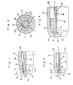
- FIG. 1 An example of the prior art spark ignited propane nozzle is shown in FIG. 1 (unpublished example). This is an example recently proposed by the applicant (Japanese utility model application no. 59,000 / 1982) filed on April 21, 1982.
- the nozzle comprises an electrically conductive inner tube (1) made of copper, a cutting oxygen passage (21), an electrically conductive outer tube (2) made of copper, a gas mixture passage (22) , a ceramic insulator tube (5) and a skirted surface (6).
- the sparks are formed at (9) for example, between an edge (13) of a front end surface (7) of the inner tube and the rear end (12) of the skirt surface (6).
- the illustrated nozzle has a life problem since the ceramic insulator (5) tends to receive thermal shock from flame. More particularly, the skirt cannot be of short length for reasons of solidity and, consequently, exceeds over a relatively considerable length in front of the front end surface (7) of the inner tube. Since it is in the vicinity of the flames, the front end surface (8) of the outer tube becomes very hot, and the front end surface (19) of the ceramic insulator (5) is arranged at the immediate vicinity of the surface (8) of the front end of the outer tube. The insulator. ceramic is therefore vulnerable to heat.
- the nozzle of FIG. 1 also has the following drawback: the inner tube (1) defines gas mixture passages (16) in the form of grooves at its front part, and two adjacent grooves are separated by an axial projection (17).
- a spark "cnd to form when the electrical discharge is minimal.
- the spark will form between the front inner surface (6) of the outer tube (2) and the outer surface of an axial projection of the inner tube (1) .
- the mixture of combustion gases flows through the passages (16) in the form of grooves, spaced peripherally from each other. spark (9) occurs with high probability away from these flow locations, in other words, the spark is formed where there is no gas mixture or when the concentration of fuel is low, which frequently results in ignition difficulties.
- the present invention aims to solve the drawbacks mentioned above.
- One of the objects of this invention is therefore to produce a nozzle comprising an inner tube and an outer electrically conductive tube, a gas mixture passage being defined between these two tubes, the front end of the outer tube being flush with the surface. front end of the inner tube or protruding at the front thereof, and an insulating tube of ceramic or similar material mounted on the inner surface of the outer tube and having a front end surface approximately flush with the front surface of the inner tube or is axially set back from this surface.
- the insulator tube may have an inner surface and a rear end surface exposed to the passage of gas mixture.
- the outer tube may have at its front end an internal surface defining a skirt whose the rear end forms with a outer edge of the front end surface of the inner tube a pair of spark electrodes.
- Another object of the invention is to provide a nozzle comprising an insulator tube mounted in an inner wall of an outer tube and the front end of which is flush with the front end of an inner tube or is set back from that -ci, and an annular passage provided at a location corresponding to the front end of the insulator tube in order to communicate with the outlets of a plurality of gas mixture passages defined in an outer surface of the inner tube.
- a skirt-shaped part may or may not be provided.
- the nozzle shown comprises an electrically conductive inner tube (1) made of copper or a copper alloy, and an electrically conductive outer tube (2) made of copper or a copper alloy copper, a gas mixture passage (22) being provided between the inner tube (1) and the outer tube (2) for conveying a mixture of combustible gas composed for example of propane gas or the like and preheating oxygen.
- the reference (21) designates a cutting oxygen passage defined along the axis of the inner tube (1).
- An insulating tube (5) made of ceramic material has a front surface (19) located at the same distance from the front end surface (8) of the outer tube (2) than the front end surface (7) of the inner tube (1).
- Spark electrodes (12, 13) are located at the rear end of a skirt-like surface (6) and on the front end surface (7) of the inner tube (1), respectively.
- the part of the gas mixture passage (22) located opposite the internal surface (10) of the insulating tube (5) has a plurality of grooves (16) formed in the external periphery of the internal tube (1). As can be seen in Fig. 2, these grooves (16) are separated by projections (17) and spaced at equidistant intervals in the circumferential direction, each groove (16) extending in the axial direction.
- the preferred electrical power source for this device comprises a piezoelectric device, but it can be constituted by an outlet from the electrical network, or by a storage battery.
- a piezoelectric device it is preferably possible to obtain the percussion energy from a flow of cutting oxygen at high pressure, but also from a mechanical percussion.
- Fig. 4 showing a second embodiment of the invention, the latter differs from the embodiment of FIG. 3 in that it comprises a hollow space (11) at the front of the insulator tube (5).
- the skirt (6) is therefore shorter than in the first embodiment of the length of this recess (11), but this does not affect the effectiveness of the protection against projections of propane flames or the like.
- the gas tends to stagnate, for example by forming a vortex in or near the recess (11), and this stagnant part of the gas has a rate of thermal conduction much lower than that of the metal or the material which constitutes the outer tube (2).
- Such a phenomenon therefore offers advantages in terms of the protection of the insulating tube (5).
- that of FIG. 4 is superior with respect to the ignition of the gas which it allows since the sparks are formed at the front of the gas outlets.
- Figs. 3 and 4 have in common that the front end surface of the insulating tube is flush that of the inner tube or is recessed from it. In comparison with the construction of FIG. 1, the surface (19) of the insulator tube is arranged significantly further back. Consequently, the first and second embodiments offer the advantage of preventing thermal shocks from acting on the insulator tube, the duration of which is thus improved.
- the invention therefore protects the insulator tube well and provides it with a long service life, that is to say that the insulator tube has an extended "ignition point definition function".
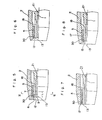
- the nozzle comprises an inner tube (1), an outer tube (2) and an insulator tube (5) made of ceramic or similar material, disposed between the two tubes (1, 2), as well as passages of combustible gas mixture in the form of grooves (16) defined on the periphery of the inner tube, opposite the internal surface of the insulating tube (5).
- the reference (21) designates a cutting oxygen passage.
- An annular passage (30) of roughly rectangular section is defined by the cutting of an inner peripheral zone of the insulator (5), since such a machining operation is relatively easy to perform. By appropriately determining the length and depth of the annular passage (30), a flame of approximately suitable shape can be obtained.
- the references (12, 13) designate the spark electrodes. This nozzle corresponds to that of FIG. 1, with in addition the passage (30) which extends on either side of the surface (7) of the tube (1).
- the nozzle of FIG. 5 includes a skirt, which is necessary in order to prevent flame splashes when using propane gas or the like as fuel.
- Figs. 6 to 8 show other examples which belong to the third embodiment.
- Fig. 6 shows a nozzle suitable for acetylene gas and not comprising a skirt.
- the annular passage (30) is defined by cutting a part of the internal surface at the front end of the insulator tube (5). This passage is of triangular section. This cutting or profiling of the insulating tube (5) is even more convenient to carry out.
- the nozzle of FIG. 7 is of a type where the front end surface of the inner tube (1) and that of the outer tube (2) are in the same plane.
- the annular passage (30) shown has the shape indicated in FIG. 5, but it can also have a triangular section as shown in FIG. 6.
- the nozzle of FIG. 8 comprises an annular passage (30) which is arranged not in the insulator tube (5) but in the front end of the inner tube (1); the annular passage can be more particularly produced by removing by cutting the ends of the projections separating the passages (16) in the form of grooves. The protrusions can be removed by cutting over their entire height at their front end.
- the third embodiment offers the following advantage: the gases which escape from the plurality of gas mixture passages (16) combine with one another in the annular passage (30) which communicates with the outlets of the gas mixture passages (16). More particularly, these gas flows which are peripherally spaced meet in the annular passage (30) and flow in an annular current. Therefore, regardless of the peripheral location where a spark occurs between the inner tube (1) and the outer tube (2), there is always a mixture of gases, which causes the ignition to occur with much more greater probability than in the devices of the prior art. The chances of ignition are not particularly determined, in this case, by the width T of each of the projections (17) described above (see Fig. 2).
Landscapes
- Engineering & Computer Science (AREA)
- Chemical & Material Sciences (AREA)
- Combustion & Propulsion (AREA)
- Mechanical Engineering (AREA)
- General Engineering & Computer Science (AREA)
- Spark Plugs (AREA)
Applications Claiming Priority (4)
| Application Number | Priority Date | Filing Date | Title |
|---|---|---|---|
| JP5915682U JPS58165459U (ja) | 1982-04-22 | 1982-04-22 | スパ−ク着火式火口 |
| JP59156/82 | 1982-04-22 | ||
| JP60162/82 | 1982-04-24 | ||
| JP6016282U JPS58165461U (ja) | 1982-04-24 | 1982-04-24 | スパ−ク着火式火口 |
Publications (2)
| Publication Number | Publication Date |
|---|---|
| EP0093047A2 true EP0093047A2 (de) | 1983-11-02 |
| EP0093047A3 EP0093047A3 (de) | 1984-04-04 |
Family
ID=26400203
Family Applications (1)
| Application Number | Title | Priority Date | Filing Date |
|---|---|---|---|
| EP83400788A Withdrawn EP0093047A3 (de) | 1982-04-22 | 1983-04-21 | Fackeldüse mit Funkenzündung |
Country Status (2)
| Country | Link |
|---|---|
| EP (1) | EP0093047A3 (de) |
| FR (1) | FR2525737A1 (de) |
Family Cites Families (2)
| Publication number | Priority date | Publication date | Assignee | Title |
|---|---|---|---|---|
| FR1343579A (fr) * | 1962-09-04 | 1963-11-22 | Harris Calorific Co | Chalumeau à allumoir |
| FR1352435A (fr) * | 1963-03-28 | 1964-02-14 | Clevite Corp | Chalumeau à gaz à allumage incorporé |
-
1983
- 1983-04-21 FR FR8306532A patent/FR2525737A1/fr active Granted
- 1983-04-21 EP EP83400788A patent/EP0093047A3/de not_active Withdrawn
Also Published As
| Publication number | Publication date |
|---|---|
| EP0093047A3 (de) | 1984-04-04 |
| FR2525737A1 (fr) | 1983-10-28 |
| FR2525737B3 (de) | 1985-02-22 |
Similar Documents
| Publication | Publication Date | Title |
|---|---|---|
| CA2649998C (fr) | Agencement d'une bougie du type a semi-conducteur dans une chambre de combustion de moteur a turbine a gaz | |
| CH624509A5 (de) | ||
| FR2579268A1 (fr) | Bruleur pour moteur stirling | |
| EP1489359B1 (de) | Ringförmige Brennkammer für eine Turbomaschine | |
| EP1186211A1 (de) | Plasmabrenner enthaltend durch einen luftspalt getrennte elektroden und einen solchen brenner enthaltender zünder | |
| EP3408522B1 (de) | Einspritzelement mit einer zündvorrichtung | |
| EP2037174B1 (de) | Handwerkzeug mit verbesserter Gasverbrennung | |
| FR2633917A1 (fr) | Ensemble generateur d'oxygene a chlorate de sodium a haut debit | |
| FR2606834A1 (fr) | Dispositif de chauffage pour collecteur d'admission de moteur a allumage par compression | |
| EP0093047A2 (de) | Fackeldüse mit Funkenzündung | |
| FR2862445A1 (fr) | Bougie d'allumage possedant une pluralite d'electrodes centrales | |
| CA1252672A (fr) | Paroi de foyer comportant des buses d'alimentation moulees en deux parties complementaires | |
| BE1006424A3 (fr) | Outil a main a dispositif d'allumage de gaz. | |
| FR2910224A1 (fr) | Torche de coupage plasma avec circuit de refroidissement a tube plongeur adaptatif | |
| WO1994016270A1 (fr) | Buse de chalumeau a gaz | |
| FR2663251A1 (fr) | Fer a souder aero-gaz a allumage piezo electrique. | |
| FR3088412A1 (fr) | Chambre de combustion de turbomachine, turbomachine associee | |
| EP2559119B1 (de) | Zündkerze mit vorrichtung zur vermeidung von kurzschlüssen | |
| FR2527311A1 (fr) | Chalumeau perfectionne du type a allumage par etincelle | |
| EP2568217B1 (de) | Strahlrohr für Handwerkzeug, das sich ohne Temperaturdispersion entlang des Rohrs aufheizt | |
| CA3223831A1 (fr) | Bruleur a gaz a combustion de surface antideflagrant et antidetonant | |
| EP0093642A2 (de) | Düse mit Funkenzündung | |
| EP0092490A2 (de) | Düse mit Funkenzündung | |
| EP3978823A1 (de) | Tragbarer heisslufterzeuger mit dämpfungssystem | |
| CH549884A (fr) | Bougie d'allumage. |
Legal Events
| Date | Code | Title | Description |
|---|---|---|---|
| PUAI | Public reference made under article 153(3) epc to a published international application that has entered the european phase |
Free format text: ORIGINAL CODE: 0009012 |
|
| 17P | Request for examination filed |
Effective date: 19830425 |
|
| AK | Designated contracting states |
Designated state(s): AT BE CH DE FR GB IT LI LU NL SE |
|
| PUAL | Search report despatched |
Free format text: ORIGINAL CODE: 0009013 |
|
| AK | Designated contracting states |
Designated state(s): AT BE CH DE FR GB IT LI LU NL SE |
|
| STAA | Information on the status of an ep patent application or granted ep patent |
Free format text: STATUS: THE APPLICATION HAS BEEN WITHDRAWN |
|
| 18W | Application withdrawn |
Withdrawal date: 19850118 |
|
| RIN1 | Information on inventor provided before grant (corrected) |
Inventor name: KUBOTA, YOSINORI |