EP0093080B1 - Clavier - Google Patents
Clavier Download PDFInfo
- Publication number
- EP0093080B1 EP0093080B1 EP83810150A EP83810150A EP0093080B1 EP 0093080 B1 EP0093080 B1 EP 0093080B1 EP 83810150 A EP83810150 A EP 83810150A EP 83810150 A EP83810150 A EP 83810150A EP 0093080 B1 EP0093080 B1 EP 0093080B1
- Authority
- EP
- European Patent Office
- Prior art keywords
- printed circuit
- circuit board
- keyboard
- keys
- molded body
- Prior art date
- Legal status (The legal status is an assumption and is not a legal conclusion. Google has not performed a legal analysis and makes no representation as to the accuracy of the status listed.)
- Expired
Links
- 238000011156 evaluation Methods 0.000 claims description 5
- 239000004020 conductor Substances 0.000 claims 1
- 230000005294 ferromagnetic effect Effects 0.000 claims 1
- 238000003780 insertion Methods 0.000 claims 1
- 230000037431 insertion Effects 0.000 claims 1
- 210000000707 wrist Anatomy 0.000 claims 1
- 239000013518 molded foam Substances 0.000 description 7
- 238000007747 plating Methods 0.000 description 3
- 238000005253 cladding Methods 0.000 description 1
- 230000007547 defect Effects 0.000 description 1
- 230000001419 dependent effect Effects 0.000 description 1
- 238000011161 development Methods 0.000 description 1
- 230000018109 developmental process Effects 0.000 description 1
- 238000006073 displacement reaction Methods 0.000 description 1
- 239000011810 insulating material Substances 0.000 description 1
- 239000002184 metal Substances 0.000 description 1
- 238000000034 method Methods 0.000 description 1
- 229910000679 solder Inorganic materials 0.000 description 1
- 238000005476 soldering Methods 0.000 description 1
- 238000012360 testing method Methods 0.000 description 1
- 238000004804 winding Methods 0.000 description 1
Images
Classifications
-
- H—ELECTRICITY
- H01—ELECTRIC ELEMENTS
- H01H—ELECTRIC SWITCHES; RELAYS; SELECTORS; EMERGENCY PROTECTIVE DEVICES
- H01H13/00—Switches having rectilinearly-movable operating part or parts adapted for pushing or pulling in one direction only, e.g. push-button switch
- H01H13/70—Switches having rectilinearly-movable operating part or parts adapted for pushing or pulling in one direction only, e.g. push-button switch having a plurality of operating members associated with different sets of contacts, e.g. keyboard
-
- H—ELECTRICITY
- H01—ELECTRIC ELEMENTS
- H01H—ELECTRIC SWITCHES; RELAYS; SELECTORS; EMERGENCY PROTECTIVE DEVICES
- H01H2207/00—Connections
- H01H2207/022—Plug
-
- H—ELECTRICITY
- H01—ELECTRIC ELEMENTS
- H01H—ELECTRIC SWITCHES; RELAYS; SELECTORS; EMERGENCY PROTECTIVE DEVICES
- H01H2217/00—Facilitation of operation; Human engineering
- H01H2217/028—Facilitation of operation; Human engineering on planes with different or alterable inclination, e.g. convex plane
-
- H—ELECTRICITY
- H01—ELECTRIC ELEMENTS
- H01H—ELECTRIC SWITCHES; RELAYS; SELECTORS; EMERGENCY PROTECTIVE DEVICES
- H01H2223/00—Casings
- H01H2223/054—Mounting of key housings on same printed circuit
-
- H—ELECTRICITY
- H01—ELECTRIC ELEMENTS
- H01H—ELECTRIC SWITCHES; RELAYS; SELECTORS; EMERGENCY PROTECTIVE DEVICES
- H01H2239/00—Miscellaneous
- H01H2239/01—Miscellaneous combined with other elements on the same substrate
-
- H—ELECTRICITY
- H01—ELECTRIC ELEMENTS
- H01H—ELECTRIC SWITCHES; RELAYS; SELECTORS; EMERGENCY PROTECTIVE DEVICES
- H01H2239/00—Miscellaneous
- H01H2239/024—Miscellaneous with inductive switch
Definitions
- the present invention relates to a keyboard in which key elements are mounted on a circuit board.
- blind plates arranged in front of or behind the circuit board have been provided until today.
- Blind plates in front of the printed circuit board are mostly metal plates, which have a shape-appropriate recess for each key element, into which the key element is inserted and usually held in place with resilient locking lugs (CH-A No. 586460).
- CH-A No. 586460 resilient locking lugs
- the electrical connections can be soldered into a circuit board behind the blind plate. It is clear that this blind plate is a relatively expensive element due to its many recesses.
- Blind plates behind the printed circuit board if they are metallic, must be insulated from the latter or, if they are made of insulating material, have a sufficient thickness or ribs, with the disadvantage of high weight or great overall height.
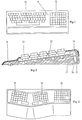
- FIG. 1 shows the layout of a keyboard with two keypads and Figure 2 shows a section through such a keyboard.
- the keyboard of Fig. 1 has a cover 11 through which an alphanumeric keypad 12 and a field 13 with z. B. Function keys pass through. From the section in Fig. 2 it can be seen that the cover 21 rises from a support surface, not shown, at a small angle, continues after an offset at the same angle over the keypad, is bent twice after the keypad and runs back against the support surface.
- Key elements 22 are mounted on a circuit board 23 below the cover 21.
- a further printed circuit board 25 is connected via a plug 24, which carries the elements 26 of an evaluation electronics.
- the plug 24 is advantageously soldered into the circuit board 25 and the circuit board 23 is connected by direct plugging.
- the printed circuit board carrying the key elements 22 is supported by a molded foam body 27, which body fills the entire remaining cavity below the cover 11 and is fastened to it.
- the molded foam body advantageously also forms the bottom of the keyboard.
- the use of this molded foam body results in a considerable reduction in mechanical parts and therefore also a reduction in weight.
- management keyboards i.e. H.
- this reduction in weight as a result of the reduction in the impact energy leads to lighter designs which are nevertheless able to pass drop tests.
- FIG. 3 corresponds approximately to the keyboard described in EP-A2 No. 0055220 (published on June 30, 1982), in which the key fields 31 - 33 are angled towards each other and have different inclinations in relation to a support surface in order to achieve an ergonomically better posture, in which the hands have to be angled and screwed in less than is necessary with a conventional one-piece or flat keyboard.
- the division of the electrical circuits into two printed circuit boards 23 and 25 connected by the plug 24 has the advantage that in the case of a transformer keyboard for the relatively large printed circuit board, which contains the primary and secondary windings of the key transformers and carries the key elements, an inexpensive, double-sided cladding Printed circuit board can be used, which no connections between the two facing sides, i. H. no through plating and no soldering process required. The absence of solder joints on this printed circuit board allows them to be placed directly on the molded foam body, at best with the interposition of an insulating film.
- the evaluation electronics on the other hand, require through plating, but can be accommodated on the relatively small circuit board 25. Although an additional plug is required to connect the two circuit boards, the three elements together are cheaper than a single larger circuit board with through-plating.
- This division also makes it possible to make the keyboard as small as possible in terms of the desired key pitch, since in this way the evaluation electronics do not require any space in the depth or width of the keyboard, but are accommodated where the space is required because of the ergonomically necessary Inclination of the keyboard is present anyway.
- the division also results in a simpler shape of the molded foam body and allows in the event of a defect, simply replace the evaluation electronics.
Landscapes
- Push-Button Switches (AREA)
- Input From Keyboards Or The Like (AREA)
Claims (5)
Priority Applications (1)
| Application Number | Priority Date | Filing Date | Title |
|---|---|---|---|
| AT83810150T ATE15843T1 (de) | 1982-04-15 | 1983-04-13 | Tastatur. |
Applications Claiming Priority (2)
| Application Number | Priority Date | Filing Date | Title |
|---|---|---|---|
| CH2283/82 | 1982-04-15 | ||
| CH228382 | 1982-04-15 |
Publications (2)
| Publication Number | Publication Date |
|---|---|
| EP0093080A1 EP0093080A1 (fr) | 1983-11-02 |
| EP0093080B1 true EP0093080B1 (fr) | 1985-09-25 |
Family
ID=4230149
Family Applications (1)
| Application Number | Title | Priority Date | Filing Date |
|---|---|---|---|
| EP83810150A Expired EP0093080B1 (fr) | 1982-04-15 | 1983-04-13 | Clavier |
Country Status (5)
| Country | Link |
|---|---|
| EP (1) | EP0093080B1 (fr) |
| JP (1) | JPS5916227A (fr) |
| AT (1) | ATE15843T1 (fr) |
| CA (1) | CA1211531A (fr) |
| DE (1) | DE3360872D1 (fr) |
Cited By (1)
| Publication number | Priority date | Publication date | Assignee | Title |
|---|---|---|---|---|
| USD310680S (en) | 1987-09-28 | 1990-09-18 | Proizvodnja in prodaja igrac, pisal, kovinskih in plasticnih izdelkov "Mehano", p.o. | Electronic typewriter |
Families Citing this family (3)
| Publication number | Priority date | Publication date | Assignee | Title |
|---|---|---|---|---|
| FR2614120A1 (fr) * | 1987-04-17 | 1988-10-21 | C P Clare Electronique | Clavier electronique |
| DE4004116C2 (de) * | 1990-02-10 | 1997-08-21 | Leybold Ag | Verfahren zum Beschichten eines Kunststoffsubstrats, vorzugsweise eines Polymethylmethacrylat-Substrats, mit Metallen sowie Vorrichtung zur Durchführung des Verfahrens |
| JP3437958B2 (ja) * | 2001-01-23 | 2003-08-18 | 株式会社エルコム | キーボード装置およびその製造方法 |
Family Cites Families (2)
| Publication number | Priority date | Publication date | Assignee | Title |
|---|---|---|---|---|
| CA999374A (en) * | 1973-08-15 | 1976-11-02 | Illinois Tool Works Inc. | Magnetic key switch having a removable support assembly |
| JPS57125069A (en) * | 1980-12-19 | 1982-08-04 | Int Standard Electric Corp | Key board device |
-
1983
- 1983-04-13 EP EP83810150A patent/EP0093080B1/fr not_active Expired
- 1983-04-13 AT AT83810150T patent/ATE15843T1/de not_active IP Right Cessation
- 1983-04-13 DE DE8383810150T patent/DE3360872D1/de not_active Expired
- 1983-04-14 CA CA000425890A patent/CA1211531A/fr not_active Expired
- 1983-04-15 JP JP58065735A patent/JPS5916227A/ja active Pending
Cited By (1)
| Publication number | Priority date | Publication date | Assignee | Title |
|---|---|---|---|---|
| USD310680S (en) | 1987-09-28 | 1990-09-18 | Proizvodnja in prodaja igrac, pisal, kovinskih in plasticnih izdelkov "Mehano", p.o. | Electronic typewriter |
Also Published As
| Publication number | Publication date |
|---|---|
| ATE15843T1 (de) | 1985-10-15 |
| CA1211531A (fr) | 1986-09-16 |
| DE3360872D1 (en) | 1985-10-31 |
| JPS5916227A (ja) | 1984-01-27 |
| EP0093080A1 (fr) | 1983-11-02 |
Similar Documents
| Publication | Publication Date | Title |
|---|---|---|
| DE3700418C2 (fr) | ||
| DE2635888A1 (de) | Tastenfeld zur betaetigung elektrischer geraete | |
| DE3529218A1 (de) | Anschlussvorrichtung fuer schaltungsplatten | |
| DE2540011B2 (de) | Elektronischer Rechner | |
| EP0093080B1 (fr) | Clavier | |
| DE2812332C3 (de) | Vielfachsteckverbindung für Karten mit gedruckter Schaltung | |
| DE3643124A1 (de) | Tastatur | |
| DE8715073U1 (de) | Elektronische Baueinheit zur Steuerung von Funktionen eines Kraftfahrzeugs | |
| EP0176617A1 (fr) | Horloge commutatrice électronique | |
| EP0019667A1 (fr) | Dispositif de fixation d'une cellule d'affichage à cristaux liquides sur une plaque de support | |
| DE8105649U1 (de) | Tastatur für Fernsprechgeräte | |
| DE3141996C2 (de) | Kochtableau | |
| EP0607844A1 (fr) | Elément isolant en une pièce, en particulier une pièce faite par moulage par injection | |
| DE7810941U1 (de) | Hochfrequenzdichte Baugruppe für Geräte der elektrischen Nachrichtentechnik | |
| DE4416096A1 (de) | Kontaktierung von Betätigungs- und Anzeigemitteln | |
| DE3518074C2 (de) | Modulbauelement für die Bildung von Geräten für den Dialog zwischen einer Bedienungsperson und einem Datenverarbeitungssystem | |
| DE3215191A1 (de) | Kontaktmatrix | |
| DE2736545A1 (de) | Steckeinheit mit einer elektrische bauelemente tragenden leiterplatte | |
| DE3706739C2 (fr) | ||
| DE3709306A1 (de) | Druckschalter, insbesondere einer tastatur | |
| EP0384269B1 (fr) | Tablette numérisatrice | |
| DE3009236C2 (de) | Anordnung mit Kontaktbuchsen für elektrische Anschlüsse | |
| DE2752665A1 (de) | Anordnung zur loetverbindung von zwei in zwei unterschiedlichen, vorzugsweise senkrecht zueinander stehenden ebenen liegenden platinen | |
| DE1286590B (de) | Logarithmisch-periodische Dipolantenne | |
| DE2347441C3 (de) | Verfahren zur Befestigung von Anzeigeelementen an einer Grundplatte eines Rechners, die mit einem Gehäuseteil des Rechners verbunden wird |
Legal Events
| Date | Code | Title | Description |
|---|---|---|---|
| PUAI | Public reference made under article 153(3) epc to a published international application that has entered the european phase |
Free format text: ORIGINAL CODE: 0009012 |
|
| AK | Designated contracting states |
Designated state(s): AT BE CH DE FR GB IT LI NL SE |
|
| RAP1 | Party data changed (applicant data changed or rights of an application transferred) |
Owner name: INTERNATIONAL STANDARD ELECTRIC CORPORATION Owner name: STANDARD TELEPHON UND RADIO AG |
|
| 17P | Request for examination filed |
Effective date: 19840315 |
|
| GRAA | (expected) grant |
Free format text: ORIGINAL CODE: 0009210 |
|
| AK | Designated contracting states |
Designated state(s): AT BE CH DE FR GB IT LI NL SE |
|
| REF | Corresponds to: |
Ref document number: 15843 Country of ref document: AT Date of ref document: 19851015 Kind code of ref document: T |
|
| REF | Corresponds to: |
Ref document number: 3360872 Country of ref document: DE Date of ref document: 19851031 |
|
| ITF | It: translation for a ep patent filed | ||
| BECA | Be: change of holder's address |
Free format text: 850925 *ALCATEL N.V.STRAWINSKYLAAN 537, NL-1077 XX AMSTERDAM |
|
| BECH | Be: change of holder |
Free format text: 850925 *ALCATEL N.V. |
|
| ET | Fr: translation filed | ||
| PLBE | No opposition filed within time limit |
Free format text: ORIGINAL CODE: 0009261 |
|
| STAA | Information on the status of an ep patent application or granted ep patent |
Free format text: STATUS: NO OPPOSITION FILED WITHIN TIME LIMIT |
|
| 26N | No opposition filed | ||
| PGFP | Annual fee paid to national office [announced via postgrant information from national office to epo] |
Ref country code: NL Payment date: 19870430 Year of fee payment: 5 |
|
| REG | Reference to a national code |
Ref country code: FR Ref legal event code: TP |
|
| REG | Reference to a national code |
Ref country code: GB Ref legal event code: 732 |
|
| NLS | Nl: assignments of ep-patents |
Owner name: ALCATEL N.V. TE AMSTERDAM. |
|
| ITPR | It: changes in ownership of a european patent |
Owner name: CESSIONE;ALCATEL N.V. |
|
| PGFP | Annual fee paid to national office [announced via postgrant information from national office to epo] |
Ref country code: GB Payment date: 19890331 Year of fee payment: 7 |
|
| PG25 | Lapsed in a contracting state [announced via postgrant information from national office to epo] |
Ref country code: LI Effective date: 19890430 Ref country code: FR Effective date: 19890430 Ref country code: CH Effective date: 19890430 Ref country code: BE Effective date: 19890430 |
|
| BERE | Be: lapsed |
Owner name: ALCATEL N.V. Effective date: 19890430 |
|
| PG25 | Lapsed in a contracting state [announced via postgrant information from national office to epo] |
Ref country code: NL Effective date: 19891101 |
|
| NLV4 | Nl: lapsed or anulled due to non-payment of the annual fee | ||
| REG | Reference to a national code |
Ref country code: CH Ref legal event code: PL |
|
| PG25 | Lapsed in a contracting state [announced via postgrant information from national office to epo] |
Ref country code: DE Effective date: 19900103 |
|
| PGFP | Annual fee paid to national office [announced via postgrant information from national office to epo] |
Ref country code: AT Payment date: 19900412 Year of fee payment: 8 |
|
| PG25 | Lapsed in a contracting state [announced via postgrant information from national office to epo] |
Ref country code: GB Effective date: 19900413 |
|
| PGFP | Annual fee paid to national office [announced via postgrant information from national office to epo] |
Ref country code: SE Payment date: 19900419 Year of fee payment: 8 |
|
| GBPC | Gb: european patent ceased through non-payment of renewal fee | ||
| REG | Reference to a national code |
Ref country code: FR Ref legal event code: ST |
|
| PG25 | Lapsed in a contracting state [announced via postgrant information from national office to epo] |
Ref country code: AT Effective date: 19910413 |
|
| PG25 | Lapsed in a contracting state [announced via postgrant information from national office to epo] |
Ref country code: SE Effective date: 19910414 |
|
| EUG | Se: european patent has lapsed |
Ref document number: 83810150.9 Effective date: 19911108 |