EP0093203A1 - Installation de séparation des impuretés solides de l'eau de refroidissement des centrales etc. - Google Patents
Installation de séparation des impuretés solides de l'eau de refroidissement des centrales etc. Download PDFInfo
- Publication number
- EP0093203A1 EP0093203A1 EP82200496A EP82200496A EP0093203A1 EP 0093203 A1 EP0093203 A1 EP 0093203A1 EP 82200496 A EP82200496 A EP 82200496A EP 82200496 A EP82200496 A EP 82200496A EP 0093203 A1 EP0093203 A1 EP 0093203A1
- Authority
- EP
- European Patent Office
- Prior art keywords
- drum
- cooling water
- guide plate
- screening drum
- cylinder housing
- Prior art date
- Legal status (The legal status is an assumption and is not a legal conclusion. Google has not performed a legal analysis and makes no representation as to the accuracy of the status listed.)
- Granted
Links
Images
Classifications
-
- B—PERFORMING OPERATIONS; TRANSPORTING
- B01—PHYSICAL OR CHEMICAL PROCESSES OR APPARATUS IN GENERAL
- B01D—SEPARATION
- B01D36/00—Filter circuits or combinations of filters with other separating devices
-
- B—PERFORMING OPERATIONS; TRANSPORTING
- B04—CENTRIFUGAL APPARATUS OR MACHINES FOR CARRYING-OUT PHYSICAL OR CHEMICAL PROCESSES
- B04C—APPARATUS USING FREE VORTEX FLOW, e.g. CYCLONES
- B04C7/00—Apparatus not provided for in group B04C1/00, B04C3/00, or B04C5/00; Multiple arrangements not provided for in one of the groups B04C1/00, B04C3/00, or B04C5/00; Combinations of apparatus covered by two or more of the groups B04C1/00, B04C3/00, or B04C5/00
-
- B—PERFORMING OPERATIONS; TRANSPORTING
- B01—PHYSICAL OR CHEMICAL PROCESSES OR APPARATUS IN GENERAL
- B01D—SEPARATION
- B01D29/00—Filters with filtering elements stationary during filtration, e.g. pressure or suction filters, not covered by groups B01D24/00 - B01D27/00; Filtering elements therefor
- B01D29/11—Filters with filtering elements stationary during filtration, e.g. pressure or suction filters, not covered by groups B01D24/00 - B01D27/00; Filtering elements therefor with bag, cage, hose, tube, sleeve or like filtering elements
- B01D29/117—Filters with filtering elements stationary during filtration, e.g. pressure or suction filters, not covered by groups B01D24/00 - B01D27/00; Filtering elements therefor with bag, cage, hose, tube, sleeve or like filtering elements arranged for outward flow filtration
- B01D29/118—Filters with filtering elements stationary during filtration, e.g. pressure or suction filters, not covered by groups B01D24/00 - B01D27/00; Filtering elements therefor with bag, cage, hose, tube, sleeve or like filtering elements arranged for outward flow filtration open-ended
-
- B—PERFORMING OPERATIONS; TRANSPORTING
- B01—PHYSICAL OR CHEMICAL PROCESSES OR APPARATUS IN GENERAL
- B01D—SEPARATION
- B01D29/00—Filters with filtering elements stationary during filtration, e.g. pressure or suction filters, not covered by groups B01D24/00 - B01D27/00; Filtering elements therefor
- B01D29/60—Filters with filtering elements stationary during filtration, e.g. pressure or suction filters, not covered by groups B01D24/00 - B01D27/00; Filtering elements therefor integrally combined with devices for controlling the filtration
- B01D29/606—Filters with filtering elements stationary during filtration, e.g. pressure or suction filters, not covered by groups B01D24/00 - B01D27/00; Filtering elements therefor integrally combined with devices for controlling the filtration by pressure measuring
-
- B—PERFORMING OPERATIONS; TRANSPORTING
- B01—PHYSICAL OR CHEMICAL PROCESSES OR APPARATUS IN GENERAL
- B01D—SEPARATION
- B01D29/00—Filters with filtering elements stationary during filtration, e.g. pressure or suction filters, not covered by groups B01D24/00 - B01D27/00; Filtering elements therefor
- B01D29/88—Filters with filtering elements stationary during filtration, e.g. pressure or suction filters, not covered by groups B01D24/00 - B01D27/00; Filtering elements therefor having feed or discharge devices
- B01D29/90—Filters with filtering elements stationary during filtration, e.g. pressure or suction filters, not covered by groups B01D24/00 - B01D27/00; Filtering elements therefor having feed or discharge devices for feeding
- B01D29/908—Filters with filtering elements stationary during filtration, e.g. pressure or suction filters, not covered by groups B01D24/00 - B01D27/00; Filtering elements therefor having feed or discharge devices for feeding provoking a tangential stream
-
- B—PERFORMING OPERATIONS; TRANSPORTING
- B01—PHYSICAL OR CHEMICAL PROCESSES OR APPARATUS IN GENERAL
- B01D—SEPARATION
- B01D29/00—Filters with filtering elements stationary during filtration, e.g. pressure or suction filters, not covered by groups B01D24/00 - B01D27/00; Filtering elements therefor
- B01D29/88—Filters with filtering elements stationary during filtration, e.g. pressure or suction filters, not covered by groups B01D24/00 - B01D27/00; Filtering elements therefor having feed or discharge devices
- B01D29/92—Filters with filtering elements stationary during filtration, e.g. pressure or suction filters, not covered by groups B01D24/00 - B01D27/00; Filtering elements therefor having feed or discharge devices for discharging filtrate
- B01D29/925—Filters with filtering elements stationary during filtration, e.g. pressure or suction filters, not covered by groups B01D24/00 - B01D27/00; Filtering elements therefor having feed or discharge devices for discharging filtrate containing liquid displacement elements or cores
-
- B—PERFORMING OPERATIONS; TRANSPORTING
- B01—PHYSICAL OR CHEMICAL PROCESSES OR APPARATUS IN GENERAL
- B01D—SEPARATION
- B01D29/00—Filters with filtering elements stationary during filtration, e.g. pressure or suction filters, not covered by groups B01D24/00 - B01D27/00; Filtering elements therefor
- B01D29/88—Filters with filtering elements stationary during filtration, e.g. pressure or suction filters, not covered by groups B01D24/00 - B01D27/00; Filtering elements therefor having feed or discharge devices
- B01D29/94—Filters with filtering elements stationary during filtration, e.g. pressure or suction filters, not covered by groups B01D24/00 - B01D27/00; Filtering elements therefor having feed or discharge devices for discharging the filter cake, e.g. chutes
-
- B—PERFORMING OPERATIONS; TRANSPORTING
- B04—CENTRIFUGAL APPARATUS OR MACHINES FOR CARRYING-OUT PHYSICAL OR CHEMICAL PROCESSES
- B04C—APPARATUS USING FREE VORTEX FLOW, e.g. CYCLONES
- B04C3/00—Apparatus in which the axial direction of the vortex flow following a screw-thread type line remains unchanged ; Devices in which one of the two discharge ducts returns centrally through the vortex chamber, a reverse-flow vortex being prevented by bulkheads in the central discharge duct
-
- B—PERFORMING OPERATIONS; TRANSPORTING
- B04—CENTRIFUGAL APPARATUS OR MACHINES FOR CARRYING-OUT PHYSICAL OR CHEMICAL PROCESSES
- B04C—APPARATUS USING FREE VORTEX FLOW, e.g. CYCLONES
- B04C5/00—Apparatus in which the axial direction of the vortex is reversed
- B04C5/08—Vortex chamber constructions
- B04C5/10—Vortex chamber constructions with perforated walls
-
- F—MECHANICAL ENGINEERING; LIGHTING; HEATING; WEAPONS; BLASTING
- F28—HEAT EXCHANGE IN GENERAL
- F28F—DETAILS OF HEAT-EXCHANGE AND HEAT-TRANSFER APPARATUS, OF GENERAL APPLICATION
- F28F19/00—Preventing the formation of deposits or corrosion, e.g. by using filters or scrapers
- F28F19/01—Preventing the formation of deposits or corrosion, e.g. by using filters or scrapers by using means for separating solid materials from heat-exchange fluids, e.g. filters
Definitions
- the invention relates to a device for separating solid dirt particles from cooling water for power plants and.
- the like which consists of a sieve drum fixedly arranged in a cylinder housing to form an annular chamber for the axial introduction of the helically flowing cooling water, a drain pipe for the cooling water attached tangentially to the cylinder housing and a discharge pipe for the dirt particles connected to the interior of the sieve drum and provided with a valve consists.
- cooling water For the cooling of heat exchangers in steam power plants or other power plant facilities, large amounts of cooling water are required, which to prevent damage and clogging of the system parts of solid dirt particles, for example pieces of wood, plastic parts, leaves, blades of grass, shells and the like. Like. Must be cleaned. While coarse dirt particles of this type are retained by upstream rakes, finer dirt particles are found for separation Chen devices use, in which the cooling water flows either from the outside in or from the inside out through a sieve drum fixed in a cylinder housing. In a known embodiment of this type, the cooling water by vortex organs, for. B. vortex valves or a tangential flow prechamber accelerated helically and introduced axially into the screening drum.
- vortex organs for. B. vortex valves or a tangential flow prechamber
- the cooling water flows outwards through the sieve drum into an annular chamber, from which it flows out via a tangentially attached drain pipe.
- the dirt particles accumulating in the sieve drum are washed out at certain time intervals by briefly opening a discharge pipe connected to the interior of the sieve drum through a valve.
- the function of such a separation device presupposes that the inner surface of the cooling water flows towards the sieve drum at an acute angle so that the dirt particles are rinsed by the tangential forces from the outer surface into the central vertebral sink and do not clog the sieve openings.
- the object of the invention is to design the device in such a way that the degree of performance is substantially improved and a deposit or partial blockage by dirt particles in the region of the drain opening is prevented.
- baffle is arranged in the annular chamber in front of the drain opening for the cooling water, which bears coaxially with an edge on the outer jacket of the sieve drum and extends in the direction of flow with increasing distance from the sieve drum.
- the arrangement of the guide plate in the annular space has the essential advantage that the pressure difference between the drain opening and the interior of the screen drum is distributed uniformly over the entire circumference of the screen drum and no longer preferably acts on the surface of the screen drum opposite the drain opening. A uniform rotational flow is hereby achieved and a direct outflow of the cooling water through the sieve drum into the outflow opening is thus prevented.
- the design and arrangement of the guide plate can vary depending on the operating conditions and flow conditions, it being able to extend over approximately 1/3 to 2/3 of the circumference of the screening drum; it preferably extends over approximately half the circumference of the screening drum.
- the angle between the guide plate and the outer jacket of the screen drum suitably corresponds approximately to the flow angle of the cooling water on the inner jacket of the screen drum.
- the favorable distribution of the pressure conditions can be further optimized by arranging the screen drum eccentrically in the cylinder housing, the smallest radial distance between the two components being on the side where the free edge of the guide plate is located.
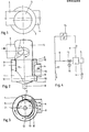
- FIGS. 1 to 3 of a device for separating solid dirt particles from cooling water consists essentially of a cylinder housing 1, in which a sieve drum 2 is arranged axially such that an annular chamber 3 is formed between the two components.
- the sieve drum can have a hole percentage of 40%, for example.
- a drain pipe 4 is attached to the cylinder housing such that it is laterally offset from the central axis and ensures a tangential outflow.
- a cylindrical dome 5 is attached, which is provided with a tangential inlet pipe 6.
- the cooling water flows through the inflow pipe 6 into the dome 5 and undergoes a helical rotational movement there, so that it flows helically into the interior of the screening drum 2.
- a discharge pipe 8 is attached, which is equipped with a valve 15 explained in more detail below.
- a baffle 10 is arranged according to the invention, which is semicircular is formed and rests with an edge 11 on the outer jacket of the screen drum 2, while the other edge 12 has an increasing distance from the screen drum in the flow direction.
- a crescent-shaped space is formed between the screen drum 2 and guide plate 10.
- the angle ⁇ between the guide plate 10 and the sieve drum 2 should preferably correspond to the inflow angle fl of the cooling water with which the cooling water flows against the inner jacket of the sieve drum 2.
- the guide plate 10 has a semicircular cross section and extends over half the circumference of the screen drum 2.
- the free edge 12 lying in the direction of flow is at a distance a from the screen drum 2, which preferably corresponds to half the distance b between the screen drum 2 and the cylinder housing 1.
- the guide plate 10 can also comprise a smaller or larger area of the screening drum 2. It is only essential that the baffle plate 10 screens the screening drum 2 with respect to the discharge opening 9 and has the aforementioned aerodynamic properties.
- the cooling water mixed with dirt particles passes through the inflow pipe 6 into the dome 5 during normal cleaning operation, is rotated there and flows axially into the sieve drum 2 in a helical manner. There it flows onto the inner surface of the screening drum 2 at an angle p. As the water flows through the sieve drum 2, dirt particles are retained and, as a result of the rotational flow, flowed from the inner lateral surface into the axial vertebra.
- the arrangement of the guide plate 10 means that the lower pressure prevailing at the discharge opening 9 cannot have an immediate effect on the opposite surface of the sieve drum. Rather, the cooling water gets into this area the crescent-shaped space 13 in plan.
- valve 15 assigned to the drain pipe 8 (see also FIG. 4) is opened and a brief rinsing process is carried out. After this valve 15 is closed, the normal separation process takes place again.
- a cooling water system is shown in a block diagram.
- This block diagram shows that the cooling water leaving the drain pipe 4 is passed through a heat exchanger 14 of a thermal power plant or the like.
- the drain line is designated 17.
- the valve 15 assigned to the discharge pipe 8 is controlled by a servomotor 16, this servomotor 16 being controlled, for example, by measuring the pressure difference between the inflow pipe 6 and the outflow pipe 4.
- the water washing out the dirt particles can be passed directly from the valve 15 into the drain line 17, bypassing the heat exchanger 14.
- the guide plate can also only extend over 1/3 or 2/3 of the circumference of the screening drum. The distance a would then be adjusted accordingly.
- the discharge pipe 8 can also be arranged laterally on the cylinder housing 1 and connected tangentially to the screening drum 2.
Landscapes
- Chemical & Material Sciences (AREA)
- Chemical Kinetics & Catalysis (AREA)
- Separation Of Solids By Using Liquids Or Pneumatic Power (AREA)
- Combined Means For Separation Of Solids (AREA)
- Cyclones (AREA)
- Physical Or Chemical Processes And Apparatus (AREA)
- Heat-Exchange Devices With Radiators And Conduit Assemblies (AREA)
- Centrifugal Separators (AREA)
- Water Treatment By Sorption (AREA)
- Physical Water Treatments (AREA)
- Treatment Of Liquids With Adsorbents In General (AREA)
Priority Applications (9)
| Application Number | Priority Date | Filing Date | Title |
|---|---|---|---|
| DE8282200496T DE3268494D1 (en) | 1982-04-26 | 1982-04-26 | Installation for the removal of solid impurities from cooling water for power stations, etc. |
| EP82200496A EP0093203B1 (fr) | 1982-04-26 | 1982-04-26 | Installation de séparation des impuretés solides de l'eau de refroidissement des centrales etc. |
| AT82200496T ATE17448T1 (de) | 1982-04-26 | 1982-04-26 | Vorrichtung zum abscheiden fester schmutzteilchen aus kuehlwasser fuer kraftwerke u. dgl. |
| AU13754/83A AU541885B2 (en) | 1982-04-26 | 1983-04-02 | Device for separating solid impurity particles from cooling water for thermal stations or the like |
| PCT/EP1983/000099 WO1983003780A1 (fr) | 1982-04-26 | 1983-04-02 | Dispositif pour separer les particules d'impurete solides de l'eau de refroidissement pour centrales thermiques ou analogues |
| JP58501180A JPS59500460A (ja) | 1982-04-26 | 1983-04-02 | 発電所などのための冷却水から固体の汚れ粒子を分離するための装置 |
| CA000425662A CA1204390A (fr) | 1982-04-26 | 1983-04-12 | Dispositif d'extraction des solides de l'eau de refroidissement des centrales energetiques |
| KR1019830001706A KR870001286B1 (ko) | 1982-04-26 | 1983-04-22 | 냉각수의 오물입자 분리장치 |
| US06/579,904 US4551247A (en) | 1982-04-26 | 1983-04-26 | Device for separating solid particles of dirt from cooling water for power stations |
Applications Claiming Priority (1)
| Application Number | Priority Date | Filing Date | Title |
|---|---|---|---|
| EP82200496A EP0093203B1 (fr) | 1982-04-26 | 1982-04-26 | Installation de séparation des impuretés solides de l'eau de refroidissement des centrales etc. |
Publications (2)
| Publication Number | Publication Date |
|---|---|
| EP0093203A1 true EP0093203A1 (fr) | 1983-11-09 |
| EP0093203B1 EP0093203B1 (fr) | 1986-01-15 |
Family
ID=8189483
Family Applications (1)
| Application Number | Title | Priority Date | Filing Date |
|---|---|---|---|
| EP82200496A Expired EP0093203B1 (fr) | 1982-04-26 | 1982-04-26 | Installation de séparation des impuretés solides de l'eau de refroidissement des centrales etc. |
Country Status (9)
| Country | Link |
|---|---|
| US (1) | US4551247A (fr) |
| EP (1) | EP0093203B1 (fr) |
| JP (1) | JPS59500460A (fr) |
| KR (1) | KR870001286B1 (fr) |
| AT (1) | ATE17448T1 (fr) |
| AU (1) | AU541885B2 (fr) |
| CA (1) | CA1204390A (fr) |
| DE (1) | DE3268494D1 (fr) |
| WO (1) | WO1983003780A1 (fr) |
Cited By (7)
| Publication number | Priority date | Publication date | Assignee | Title |
|---|---|---|---|---|
| FR2554734A1 (fr) * | 1983-11-15 | 1985-05-17 | Dango & Dienenthal Maschbau | Filtre a liquide |
| EP0939666A4 (fr) * | 1997-04-30 | 1999-09-08 | ||
| EP0995856A1 (fr) * | 1998-10-15 | 2000-04-26 | GEP Umwelttechnik GmbH | Filtre de citerne |
| WO2007083296A3 (fr) * | 2006-01-23 | 2007-11-22 | Netafim Ltd | Systemes de filtration et bassins de filtration destines a etre utilises dans les systemes |
| WO2012136801A1 (fr) * | 2011-04-08 | 2012-10-11 | Beko Technologies Gmbh | Tête de filtrage à écoulement optimisé |
| WO2012052396A3 (fr) * | 2010-10-19 | 2012-12-06 | Dürr Systems GmbH | Installation de transfert de chaleur ou de froid à un milieu fluide |
| CN103112964A (zh) * | 2013-01-25 | 2013-05-22 | 陈骐 | 污水处理系统及处理污水的工艺流程 |
Families Citing this family (13)
| Publication number | Priority date | Publication date | Assignee | Title |
|---|---|---|---|---|
| ATE183940T1 (de) * | 1993-02-11 | 1999-09-15 | Stephen Crompton | Vorrichtung zur abtrennung von feststoffen aus einer strömenden flüssigkeit |
| AUPM628594A0 (en) * | 1994-06-17 | 1994-07-07 | Blanche, Paul | An apparatus for the separation of solids from flowing liquid |
| KR20010019589A (ko) * | 1999-08-28 | 2001-03-15 | 이구택 | 콘덴서용 냉각수 수조부의 슬러지 배출장치 |
| US6348087B1 (en) | 2000-01-10 | 2002-02-19 | Shaw Aero Devices, Inc. | Three phase cyclonic separator |
| NO20020093D0 (no) * | 2002-01-09 | 2002-01-09 | Optimarin As | Fremgangsmåte for å skille ulike partikler og organismer med lav egenvekt fra v¶sker i en hydrosyklon med et filter |
| DE10248638A1 (de) * | 2002-10-18 | 2004-05-06 | Hydac Process Technology Gmbh | Abscheidevorrichtung, insbesondere zur Abscheidung von Feststoffen aus Flüssigkeiten |
| US6991114B2 (en) | 2003-09-17 | 2006-01-31 | Vortechnics, Inc. | Apparatus for separating floating and non-floating particulate from a fluid stream |
| US7465391B2 (en) | 2005-09-09 | 2008-12-16 | Cds Technologies, Inc. | Apparatus for separating solids from flowing liquids |
| JP5137109B2 (ja) * | 2007-07-10 | 2013-02-06 | シャープ株式会社 | 分離塔および懸濁物質分離装置 |
| US8287726B2 (en) | 2007-08-15 | 2012-10-16 | Monteco Ltd | Filter for removing sediment from water |
| US8221618B2 (en) * | 2007-08-15 | 2012-07-17 | Monteco Ltd. | Filter for removing sediment from water |
| JP5908687B2 (ja) * | 2011-08-24 | 2016-04-26 | 株式会社カワタ | 螺旋流発生装置 |
| DE102020203699A1 (de) * | 2020-03-23 | 2021-09-23 | Georg Klaß, jun. | Anlage zur Trennung suspendierter Stoffe aus einer Flüssigkeit mit einer Filteranordnung nach Art eines Zyklonfilters |
Citations (5)
| Publication number | Priority date | Publication date | Assignee | Title |
|---|---|---|---|---|
| US1571736A (en) * | 1925-04-07 | 1926-02-02 | Improved Paper Machinery Compa | Screen |
| US2913114A (en) * | 1952-10-14 | 1959-11-17 | Maskin Aktiebolaget Plavia | Process and an apparatus for separating solids from suspensions of solids in fluids |
| US2998137A (en) * | 1959-02-13 | 1961-08-29 | Vane Zdenek | Centrifugal screen |
| US3985522A (en) * | 1971-05-25 | 1976-10-12 | Deepsea Ventures, Inc. | Method and apparatus for separating solid particles from a mixed fluid stream |
| DE2708135A1 (de) * | 1977-02-25 | 1978-08-31 | Schauenburg Masch | Vorrichtung zur aufbereitung von truebe |
Family Cites Families (11)
| Publication number | Priority date | Publication date | Assignee | Title |
|---|---|---|---|---|
| US2226045A (en) * | 1939-07-19 | 1940-12-24 | New York Air Brake Co | Air filter |
| US2902156A (en) * | 1956-03-22 | 1959-09-01 | Dahlberg Bengt Georg | Centrifugal screens |
| US3088595A (en) * | 1959-10-07 | 1963-05-07 | British Oxygen Co Ltd | Filter unit |
| US3067876A (en) * | 1960-02-15 | 1962-12-11 | Rain Jet Corp | Centrifugal separator process and apparatus |
| US3771290A (en) * | 1971-12-06 | 1973-11-13 | Armstrong Ltd S A | Vortex de-aerator |
| FR2273572A1 (fr) * | 1974-06-07 | 1976-01-02 | Lab | Perfectionnements au traitement des fluides pollues par des particules solides |
| FR2355544A1 (fr) * | 1976-06-22 | 1978-01-20 | Beaudrey & Cie | Filtre a crepine fixe pour eaux industrielles |
| US4199443A (en) * | 1978-05-30 | 1980-04-22 | Tauber Thomas E | Oil monitoring apparatus |
| DE2830386C2 (de) * | 1978-07-11 | 1982-09-02 | Hermann Finckh, Maschinenfabrik GmbH & Co, 7417 Pfullingen | Verfahren zum Sortieren von Fasersuspensionen sowie Drucksortierer zur Durchführung des Verfahrens |
| FR2477028A1 (fr) * | 1980-03-03 | 1981-09-04 | Beaudrey & Cie | Filtre a crepine fixe, notamment pour eaux industrielles |
| US4318805A (en) * | 1980-09-29 | 1982-03-09 | Bird Machine Company, Inc. | Screening apparatus |
-
1982
- 1982-04-26 AT AT82200496T patent/ATE17448T1/de not_active IP Right Cessation
- 1982-04-26 DE DE8282200496T patent/DE3268494D1/de not_active Expired
- 1982-04-26 EP EP82200496A patent/EP0093203B1/fr not_active Expired
-
1983
- 1983-04-02 AU AU13754/83A patent/AU541885B2/en not_active Ceased
- 1983-04-02 WO PCT/EP1983/000099 patent/WO1983003780A1/fr not_active Ceased
- 1983-04-02 JP JP58501180A patent/JPS59500460A/ja active Granted
- 1983-04-12 CA CA000425662A patent/CA1204390A/fr not_active Expired
- 1983-04-22 KR KR1019830001706A patent/KR870001286B1/ko not_active Expired
- 1983-04-26 US US06/579,904 patent/US4551247A/en not_active Expired - Fee Related
Patent Citations (5)
| Publication number | Priority date | Publication date | Assignee | Title |
|---|---|---|---|---|
| US1571736A (en) * | 1925-04-07 | 1926-02-02 | Improved Paper Machinery Compa | Screen |
| US2913114A (en) * | 1952-10-14 | 1959-11-17 | Maskin Aktiebolaget Plavia | Process and an apparatus for separating solids from suspensions of solids in fluids |
| US2998137A (en) * | 1959-02-13 | 1961-08-29 | Vane Zdenek | Centrifugal screen |
| US3985522A (en) * | 1971-05-25 | 1976-10-12 | Deepsea Ventures, Inc. | Method and apparatus for separating solid particles from a mixed fluid stream |
| DE2708135A1 (de) * | 1977-02-25 | 1978-08-31 | Schauenburg Masch | Vorrichtung zur aufbereitung von truebe |
Cited By (9)
| Publication number | Priority date | Publication date | Assignee | Title |
|---|---|---|---|---|
| FR2554734A1 (fr) * | 1983-11-15 | 1985-05-17 | Dango & Dienenthal Maschbau | Filtre a liquide |
| EP0939666A4 (fr) * | 1997-04-30 | 1999-09-08 | ||
| US6210575B1 (en) | 1997-04-30 | 2001-04-03 | The University Of Akron | Crossflow filter cyclone apparatus |
| EP0995856A1 (fr) * | 1998-10-15 | 2000-04-26 | GEP Umwelttechnik GmbH | Filtre de citerne |
| WO2007083296A3 (fr) * | 2006-01-23 | 2007-11-22 | Netafim Ltd | Systemes de filtration et bassins de filtration destines a etre utilises dans les systemes |
| WO2012052396A3 (fr) * | 2010-10-19 | 2012-12-06 | Dürr Systems GmbH | Installation de transfert de chaleur ou de froid à un milieu fluide |
| WO2012136801A1 (fr) * | 2011-04-08 | 2012-10-11 | Beko Technologies Gmbh | Tête de filtrage à écoulement optimisé |
| CN103112964A (zh) * | 2013-01-25 | 2013-05-22 | 陈骐 | 污水处理系统及处理污水的工艺流程 |
| CN103112964B (zh) * | 2013-01-25 | 2014-06-11 | 陈骐 | 污水处理系统及处理污水的工艺流程 |
Also Published As
| Publication number | Publication date |
|---|---|
| KR870001286B1 (ko) | 1987-07-11 |
| CA1204390A (fr) | 1986-05-13 |
| AU541885B2 (en) | 1985-01-24 |
| AU1375483A (en) | 1983-11-21 |
| ATE17448T1 (de) | 1986-02-15 |
| DE3268494D1 (en) | 1986-02-27 |
| WO1983003780A1 (fr) | 1983-11-10 |
| JPS59500460A (ja) | 1984-03-22 |
| JPS6158229B2 (fr) | 1986-12-10 |
| EP0093203B1 (fr) | 1986-01-15 |
| KR840004519A (ko) | 1984-10-22 |
| US4551247A (en) | 1985-11-05 |
Similar Documents
| Publication | Publication Date | Title |
|---|---|---|
| EP0093203A1 (fr) | Installation de séparation des impuretés solides de l'eau de refroidissement des centrales etc. | |
| DE3019839C2 (de) | Vorrichtung zum Abscheiden von Feststoffen aus einem Flüssigkeitsstrom | |
| EP0026261B1 (fr) | Dispositif pour la séparation des éléments de nettoyage d'un fluide s'écoulant d'un échangeur de chaleur à tube | |
| DE69524591T2 (de) | Vorrichtung und methoden zum abtrennen von feststoffen aus strömenden flüssigkeiten oder gasen | |
| DE1761106C3 (de) | Filter zur Reinigung von mit Feststoffen vermischten Flüssigkeiten | |
| DE1436287A1 (de) | Verfahren zum Filtern eines Fluids und Anlage zur Durchfuehrung des Verfahrens | |
| DE2803224C2 (de) | Selbstreinigende Filtervorrichtung | |
| DE68904373T2 (de) | Vorrichtung zum abscheiden von abgeriebenen reinigungskugeln aus rohrbuendeln. | |
| DE3339974C2 (de) | Vorrichtung zum Entfernen von Fremdstoffen aus Kondensatorkühlwasser | |
| DE2613835C3 (de) | Kühlwasser verwendender Wärmeaustauscher | |
| DE1481380A1 (de) | Anlage zum Absaugen und Ausscheiden von Abfallprodukten von Bearbeitungsmaschinen und dabei zu benutzende Zentrifugalluftpumpe | |
| DE68917207T2 (de) | Verdampfer mit einer Vorrichtung zur Kontrolle der Strömung von Festteilchen. | |
| DE3107607C2 (fr) | ||
| DE69701288T2 (de) | Vorrichtung zur beseitigung von kugeln aus einer kühlmittelleitung | |
| DE3513166A1 (de) | Klimaanlage | |
| DE3131124C1 (de) | Reinigungsfangsieb für Kondensator-Reinigungsanlagen mit Kühlwasser-Reinigungskreislauf | |
| DE2237521B2 (de) | Altpapierstofflöser | |
| DE60010410T2 (de) | Verwaltungsvorrichtung für in einem Wärmetauscher zirkulierenden Festkörper | |
| AT407492B (de) | Filtervorrichtung für ein fliessfähiges medium, insbesondere eine schmelze | |
| DE3413413A1 (de) | Vorrichtung zum kontinuierlichen abscheiden und abfuehren von feststoffen und reinigungskoerpern aus einem fluessigkeitsstrom | |
| DE2355768C2 (de) | Siebvorrichtung zum Sortieren von Suspensionen | |
| DE1900732A1 (de) | Aus Rohren oder Rohrbuendeln bestehender Oberflaechen-Kondensator bzw.Oberflaechen-Waermeaustauscher | |
| DE2609332B2 (de) | Vorrichtung zum abscheiden von feststoffen | |
| DE2943287C2 (de) | Anlage für die Röhrenreinigung eines Kraftwerkskondensators mit Hilfe von Reinigungskugeln | |
| DE3046388C2 (de) | Spaltfilter für Flüssigkeiten |
Legal Events
| Date | Code | Title | Description |
|---|---|---|---|
| PUAI | Public reference made under article 153(3) epc to a published international application that has entered the european phase |
Free format text: ORIGINAL CODE: 0009012 |
|
| 17P | Request for examination filed |
Effective date: 19830316 |
|
| AK | Designated contracting states |
Designated state(s): AT BE CH DE FR GB IT LI LU NL SE |
|
| ITF | It: translation for a ep patent filed | ||
| GRAA | (expected) grant |
Free format text: ORIGINAL CODE: 0009210 |
|
| AK | Designated contracting states |
Designated state(s): AT BE CH DE FR GB IT LI LU NL SE |
|
| REF | Corresponds to: |
Ref document number: 17448 Country of ref document: AT Date of ref document: 19860215 Kind code of ref document: T |
|
| REF | Corresponds to: |
Ref document number: 3268494 Country of ref document: DE Date of ref document: 19860227 |
|
| ET | Fr: translation filed | ||
| PG25 | Lapsed in a contracting state [announced via postgrant information from national office to epo] |
Ref country code: LU Free format text: LAPSE BECAUSE OF NON-PAYMENT OF DUE FEES Effective date: 19860430 |
|
| R20 | Corrections of a patent specification |
Effective date: 19860407 |
|
| PLBE | No opposition filed within time limit |
Free format text: ORIGINAL CODE: 0009261 |
|
| STAA | Information on the status of an ep patent application or granted ep patent |
Free format text: STATUS: NO OPPOSITION FILED WITHIN TIME LIMIT |
|
| 26N | No opposition filed | ||
| PGFP | Annual fee paid to national office [announced via postgrant information from national office to epo] |
Ref country code: SE Payment date: 19890307 Year of fee payment: 8 |
|
| PGFP | Annual fee paid to national office [announced via postgrant information from national office to epo] |
Ref country code: BE Payment date: 19890317 Year of fee payment: 8 |
|
| PGFP | Annual fee paid to national office [announced via postgrant information from national office to epo] |
Ref country code: LU Payment date: 19890331 Year of fee payment: 8 |
|
| PGFP | Annual fee paid to national office [announced via postgrant information from national office to epo] |
Ref country code: AT Payment date: 19890428 Year of fee payment: 8 |
|
| PGFP | Annual fee paid to national office [announced via postgrant information from national office to epo] |
Ref country code: NL Payment date: 19890430 Year of fee payment: 8 |
|
| PGFP | Annual fee paid to national office [announced via postgrant information from national office to epo] |
Ref country code: CH Payment date: 19890628 Year of fee payment: 8 |
|
| PG25 | Lapsed in a contracting state [announced via postgrant information from national office to epo] |
Ref country code: AT Effective date: 19900426 |
|
| PG25 | Lapsed in a contracting state [announced via postgrant information from national office to epo] |
Ref country code: SE Effective date: 19900427 |
|
| PG25 | Lapsed in a contracting state [announced via postgrant information from national office to epo] |
Ref country code: LI Effective date: 19900430 Ref country code: CH Effective date: 19900430 Ref country code: BE Effective date: 19900430 |
|
| ITPR | It: changes in ownership of a european patent |
Owner name: CESSIONE;TAPROGGE GMBH |
|
| REG | Reference to a national code |
Ref country code: GB Ref legal event code: 732 |
|
| BERE | Be: lapsed |
Owner name: BORCHERT WERNER Effective date: 19900430 |
|
| PG25 | Lapsed in a contracting state [announced via postgrant information from national office to epo] |
Ref country code: NL Effective date: 19901101 |
|
| REG | Reference to a national code |
Ref country code: FR Ref legal event code: TP |
|
| NLV4 | Nl: lapsed or anulled due to non-payment of the annual fee | ||
| REG | Reference to a national code |
Ref country code: CH Ref legal event code: PL |
|
| PGFP | Annual fee paid to national office [announced via postgrant information from national office to epo] |
Ref country code: FR Payment date: 19920221 Year of fee payment: 11 |
|
| PGFP | Annual fee paid to national office [announced via postgrant information from national office to epo] |
Ref country code: DE Payment date: 19920319 Year of fee payment: 11 |
|
| PGFP | Annual fee paid to national office [announced via postgrant information from national office to epo] |
Ref country code: GB Payment date: 19920415 Year of fee payment: 11 |
|
| ITTA | It: last paid annual fee | ||
| PG25 | Lapsed in a contracting state [announced via postgrant information from national office to epo] |
Ref country code: GB Effective date: 19930426 |
|
| GBPC | Gb: european patent ceased through non-payment of renewal fee |
Effective date: 19930426 |
|
| PG25 | Lapsed in a contracting state [announced via postgrant information from national office to epo] |
Ref country code: FR Effective date: 19931229 |
|
| PG25 | Lapsed in a contracting state [announced via postgrant information from national office to epo] |
Ref country code: DE Effective date: 19940101 |
|
| REG | Reference to a national code |
Ref country code: FR Ref legal event code: ST |
|
| EUG | Se: european patent has lapsed |
Ref document number: 82200496.6 Effective date: 19910115 |