EP0093219A1 - Digitales Kodierungsverfahren und Anordnung zur Durchführung dieses Verfahrens - Google Patents
Digitales Kodierungsverfahren und Anordnung zur Durchführung dieses Verfahrens Download PDFInfo
- Publication number
- EP0093219A1 EP0093219A1 EP82430012A EP82430012A EP0093219A1 EP 0093219 A1 EP0093219 A1 EP 0093219A1 EP 82430012 A EP82430012 A EP 82430012A EP 82430012 A EP82430012 A EP 82430012A EP 0093219 A1 EP0093219 A1 EP 0093219A1
- Authority
- EP
- European Patent Office
- Prior art keywords
- sub
- coding
- bands
- band
- signal
- Prior art date
- Legal status (The legal status is an assumption and is not a legal conclusion. Google has not performed a legal analysis and makes no representation as to the accuracy of the status listed.)
- Granted
Links
- 238000000034 method Methods 0.000 title claims description 53
- 230000005540 biological transmission Effects 0.000 claims abstract description 82
- 238000013139 quantization Methods 0.000 claims abstract description 32
- 230000003252 repetitive effect Effects 0.000 claims abstract description 5
- 230000000694 effects Effects 0.000 claims description 20
- 238000001914 filtration Methods 0.000 claims description 18
- 238000012545 processing Methods 0.000 claims description 12
- 238000011002 quantification Methods 0.000 claims description 8
- 238000005070 sampling Methods 0.000 claims description 7
- 238000009826 distribution Methods 0.000 claims description 6
- 230000036961 partial effect Effects 0.000 claims description 4
- 230000001755 vocal effect Effects 0.000 claims description 3
- 230000008054 signal transmission Effects 0.000 claims description 2
- 230000006870 function Effects 0.000 description 12
- OQEBIHBLFRADNM-UHFFFAOYSA-N D-iminoxylitol Natural products OCC1NCC(O)C1O OQEBIHBLFRADNM-UHFFFAOYSA-N 0.000 description 6
- 102100028561 Disabled homolog 1 Human genes 0.000 description 6
- 101000915416 Homo sapiens Disabled homolog 1 Proteins 0.000 description 6
- 230000008569 process Effects 0.000 description 5
- 238000007906 compression Methods 0.000 description 4
- 230000006835 compression Effects 0.000 description 4
- 230000014509 gene expression Effects 0.000 description 4
- 230000000717 retained effect Effects 0.000 description 4
- 241001080024 Telles Species 0.000 description 3
- 230000008901 benefit Effects 0.000 description 3
- 238000010586 diagram Methods 0.000 description 3
- 230000002441 reversible effect Effects 0.000 description 3
- 241000364021 Tulsa Species 0.000 description 2
- 238000000605 extraction Methods 0.000 description 2
- 238000005259 measurement Methods 0.000 description 2
- 238000012986 modification Methods 0.000 description 2
- 230000004048 modification Effects 0.000 description 2
- 230000002829 reductive effect Effects 0.000 description 2
- 238000001228 spectrum Methods 0.000 description 2
- 102100028572 Disabled homolog 2 Human genes 0.000 description 1
- 101000915391 Homo sapiens Disabled homolog 2 Proteins 0.000 description 1
- 241000897276 Termes Species 0.000 description 1
- 230000009471 action Effects 0.000 description 1
- 230000015572 biosynthetic process Effects 0.000 description 1
- 238000004364 calculation method Methods 0.000 description 1
- 230000008094 contradictory effect Effects 0.000 description 1
- 238000007796 conventional method Methods 0.000 description 1
- 101150047356 dec-1 gene Proteins 0.000 description 1
- 230000008014 freezing Effects 0.000 description 1
- 238000007710 freezing Methods 0.000 description 1
- 238000010606 normalization Methods 0.000 description 1
- 230000008447 perception Effects 0.000 description 1
- 238000011160 research Methods 0.000 description 1
- 230000033764 rhythmic process Effects 0.000 description 1
- 230000007480 spreading Effects 0.000 description 1
- 238000003786 synthesis reaction Methods 0.000 description 1
Images


Classifications
-
- H—ELECTRICITY
- H04—ELECTRIC COMMUNICATION TECHNIQUE
- H04B—TRANSMISSION
- H04B1/00—Details of transmission systems, not covered by a single one of groups H04B3/00 - H04B13/00; Details of transmission systems not characterised by the medium used for transmission
- H04B1/66—Details of transmission systems, not covered by a single one of groups H04B3/00 - H04B13/00; Details of transmission systems not characterised by the medium used for transmission for reducing bandwidth of signals; for improving efficiency of transmission
- H04B1/667—Details of transmission systems, not covered by a single one of groups H04B3/00 - H04B13/00; Details of transmission systems not characterised by the medium used for transmission for reducing bandwidth of signals; for improving efficiency of transmission using a division in frequency subbands
-
- G—PHYSICS
- G10—MUSICAL INSTRUMENTS; ACOUSTICS
- G10L—SPEECH ANALYSIS TECHNIQUES OR SPEECH SYNTHESIS; SPEECH RECOGNITION; SPEECH OR VOICE PROCESSING TECHNIQUES; SPEECH OR AUDIO CODING OR DECODING
- G10L19/00—Speech or audio signals analysis-synthesis techniques for redundancy reduction, e.g. in vocoders; Coding or decoding of speech or audio signals, using source filter models or psychoacoustic analysis
- G10L19/04—Speech or audio signals analysis-synthesis techniques for redundancy reduction, e.g. in vocoders; Coding or decoding of speech or audio signals, using source filter models or psychoacoustic analysis using predictive techniques
- G10L19/16—Vocoder architecture
- G10L19/18—Vocoders using multiple modes
- G10L19/24—Variable rate codecs, e.g. for generating different qualities using a scalable representation such as hierarchical encoding or layered encoding
-
- G—PHYSICS
- G10—MUSICAL INSTRUMENTS; ACOUSTICS
- G10L—SPEECH ANALYSIS TECHNIQUES OR SPEECH SYNTHESIS; SPEECH RECOGNITION; SPEECH OR VOICE PROCESSING TECHNIQUES; SPEECH OR AUDIO CODING OR DECODING
- G10L19/00—Speech or audio signals analysis-synthesis techniques for redundancy reduction, e.g. in vocoders; Coding or decoding of speech or audio signals, using source filter models or psychoacoustic analysis
- G10L19/02—Speech or audio signals analysis-synthesis techniques for redundancy reduction, e.g. in vocoders; Coding or decoding of speech or audio signals, using source filter models or psychoacoustic analysis using spectral analysis, e.g. transform vocoders or subband vocoders
- G10L19/0204—Speech or audio signals analysis-synthesis techniques for redundancy reduction, e.g. in vocoders; Coding or decoding of speech or audio signals, using source filter models or psychoacoustic analysis using spectral analysis, e.g. transform vocoders or subband vocoders using subband decomposition
Definitions
- the present invention relates to a method of digital transmission at several speeds and its application to the concentration of digital information coming from several sources, on a single transmission channel. It more specifically applies to the transmission of digital information of vocal origin.
- the conditions for digital transmission on a given channel may vary over time. It is therefore advantageous to be able to have transmitters with several transmission speeds (number of bits per second), equipped with simple means making it possible to switch from one speed to another depending on the transmission conditions at the time.
- TDM time multiplexing
- Two lines of research can be defined, the first relates to the processing of the signal provided by each of the sources, the second is concerned with the management of sources.
- voice signal sources As these are essentially voice signal sources, the properties of the voice are taken into account for the processing of the signal supplied by a given source in order to define coding / decoding modes which, for a quantity of digital information minimal, make it possible to alter the qualities of the voice signal as little as possible.
- multiplexing techniques have already been mentioned. These techniques are basically carried out by sequential and cyclical assignment of the transmission channel to each of the sources. The limitations can easily be understood.
- the channel's transmission capacity (number of bits per second) cannot in principle be less than the sum of the bits that the different sources would provide in the same second.
- the sources of voice signals have the particularity of having intermittent activities. More precisely, for a source which a priori seems active because it is linked at a given moment to a person engaged in a conversation, we detect alternations of zones of silence or inactivity drowned in zones of effective activity .
- TASI Time Assignment Speech Interpolation
- a device is used there to permanently detect the sources of the group which, at a given instant, can be considered in active activity (according to a predetermined criterion), and to allocate the transmission channel only to these sources.
- the number L is defined from statistical rules with all that that involves risks in practical application.
- the TASI type multiplexing system may be required to delay the transmission of signals from certain sources, or even to freeze these sources outright, in other words cut them off. All these solutions are naturally inadmissible in a real-time conversational system.
- the voice signal of each of the sources of the system considered is first of all coded at a relatively high bit rate (maximum rate).
- maximum rate bit rate
- the bits obtained by coding the samples of each voice signal are placed in the stream of bits to be transmitted, in a pre-established order. This order is such that when it is desired to transmit the signal already coded at a rhythm corresponding to a coding rate lower than the maximum rate, the operations to be carried out are extremely simple. Just delete some bits.
- the number of transmission speeds possible by applying the techniques proposed by David J. Goodman is relatively limited, since these can only be multiples of the signal sampling frequency.
- the present invention relates to a simple and efficient method of multi-speed digital transmission of voice signals.
- the present invention also relates to a method for concentrating the signals of vocal origin supplied by a group of L sources, on the same transmission channel by using compression techniques and multiplexing techniques which can be combined with one another in a simple manner.
- the subject of the invention is also concentration techniques making it possible to avoid any delay or even freezing of any source during a traffic congestion period.
- the present invention proceeds by processing, with a view to compression, of the signal from each source by application of techniques involving the cutting of the bandwidth of the corresponding voice signal into a given number of sub-bands, and coding of the sub-band signals by dynamic distribution of the quantization rates between the sub-bands.
- the sub-bands are in fact grouped into sub-groups, the number of which is defined as a function of the number of possible transmission speeds.
- the coding bit rate of each subgroup is defined as a function of at least one of said possible speeds.
- the signals of the sub-bands of each sub-group are quantified by dynamic allocation of the quantization rates as a function of the coding bit rate assigned to the sub-group.
- the bits obtained by coding the signals of each subgroup considered over a given time interval are distributed in a repetitive frame of format comprising predetermined zones, each of said zones being intended to receive the bits corresponding to the coding of the signals supplied by sub - predetermined bands belonging to the same subgroup.
- each frame is possibly truncated accordingly by abandoning the bits of one or more zones before transmission.
- the above method is particularly well adapted to a concentration of voice signals from several sources on the same transmission path and assigning the most active sources, the highest coding rate.
- the method proposed by David J. Goodman keeps the bandwidth of the processed signal constant. In other words, for a transmission at reduced speed, while the number of bits intended for the coding of the signal is relatively low, these bits are always used to encode the same number of samples since the Nyquist frequency has not varied.
- a Croisier proposes to code the voice signal by consecutive sections of judiciously chosen duration (for example 20 ms). For each signal section a scale factor (or characteristic term) of the signal to be coded is defined. This term is a function of the section dynamics and serves as a reference for coding said section. More precisely, the voice signal being sampled at its Nyquist frequency, each section of signal provides a block of samples. The characteristic term C must be such that the largest sample of the block does not fall outside the limits of the coding during the time interval considered.
- each block contains N samples
- each sub-band is more or less precisely quantified (or re-quantified) according to the relative energy of the signal contained in said sub-band.
- the specific rate allocated to each sub-band will vary over time as a function of the energy of the signal contained in said sub-band.
- the method of the present invention applies regardless of the type of subband coding. It applies in particular to a coding in sub-bands of the kind described in French patent No. 77 13995 in which the entire bandwidth of the voice signal to be transmitted is split into several sub-bands. bands. It also applies to sub-band coding in which only a so-called basic band of the voice signal to be transmitted is split into sub-bands.
- An embodiment of an encoder of the latter type has been described in the European patent 0 002 998 already cited. A similar embodiment of this same type of coder was also described by D. Esteban et al at the Tulsa conference under the title 9.6 / 7.2 Kbps Voice Excited Predictive Coder (VEPC).
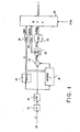
- FIG. 1 shows a VEPC type encoder.
- the voice signal is applied to the IN input of the encoder. It is filtered at 10 using a low pass filter transmitting to an analog-digital converter 12 a signal included in the so-called telephone frequency band (frequencies ⁇ 3400 Hz). This signal is sampled at 8 KHz and coded in 12-bit PCM. The coded samples are then recoded. To do this, they are sent both to a parameter predictor 14, to a subtractor 16 and to an inverse filter 18. The predictor 14 deduces from the signal that it receives a group of so-called partial autocorrelation coefficients or PARCOR (K ) used to adjust the reverse filter 18 for a duration less than or equal to 20 ms.
- PARCOR PARCOR
- the inverse filter is produced according to the mesh network as defined by JD Markel et al in their work entitled: "Linear Prediction of Speech" in paragraph 5.4.
- the signal provided by the reverse filter 18 actually represents the predictable part of the voice signal.
- the subtractor 16 subtracting from the signal supplied by the converter 12 the signal from the inverse filter 18, provides a so-called residual signal e (n) devoid of part of the redundancy of the original voice signal.
- the residual signal e (n) is filtered at 20.
- the device 20 supplies on the one hand the samples X (n) of a so-called residual signal in baseband limited to a frequency ⁇ 2 kHz for example and on the other hand a information relating to the energy of the signal contained in the eliminated high frequency band.
- the residual baseband signal is subjected to a coding in sub-bands in a device 2.2.
- This latter device performs a requantification of the type with dynamic allocation of the bits of quantification and deliver information designated by SIGNAL.
- the energy of the high frequency band (1625-3400 Hz for example) is requantified at 24 to provide information designated as ENERG (or E).
- ENERG or E
- PARCOR coefficients As for the partial autocorrelation coefficients also called PARCOR coefficients, they are recoded by requantification at 26 to provide information designated by COEF (or K).
- the device 14 predictor of parameters has been described in detail in particular in European patent 0 002 998 and more precisely in FIGS. 6 and 7 of said patent.
- the method on which the device is based notably implements the algorithms proposed by J. Le Roux and C. Guegen in an article published by IEEE Transactions on Acoustics, Speech and Signal Processing of June 1977.
- the device 20 comprises a low-pass digital filter whose upper limit frequency is ⁇ 2000 Hz. We will see later that in the practical case described, this upper frequency will be limited to 1625 Hz.
- the device 20 further comprises the means making it possible to measure the energy E contained in the high frequency band 1625-3400 Hz eliminated by the low-pass filter of the device 20.
- An embodiment of the device 20 has been described in the European patent 0 002 998 (see in particular FIG. 2 of the said patent).
- the so-called high band energy information of the residual signal is quantified at 24 and this, every 10 milliseconds, that is to say twice per signal segment of 20 milliseconds.
- the samples X (n) of the residual baseband signal leave the low-pass filter 20 at a frequency of 4 KHz.
- the residual baseband signal is subjected in encoder 22 to BCPCM sub-band recoding with dynamic allocation of the quantization bit rates between the sub-bands. This type of coding has been described in the documents cited above.
- the samples X (i, j) are themselves (re) quantified in such a way that the corresponding (re) quantization step is defined as a function of the sub-band to which the processed sample belongs or more precisely as a function of the relative energy contained in said sub-band with respect to the energies contained in the other sub-bands during the same time interval.
- M expressed per sub-band sampling period and intended for the (re) quantization of the samples of the p sub-bands
- the overall quantization signal-to-noise ratio is minimized by assigning to the requantification of the i-th sub-band, a number of bits n (i) obeying the relation: or and
- the sub-bands are grouped into several sub-groups and that the number M therefore the rate of quantification. tion varies from one subgroup to another.
- the number of sub-groups is defined according to the number of predetermined speeds at which it is proposed to be able to transmit. We chose the 2.4 speed group; 4.8; 7.2; 9.6 and 12 Kbps. Every 20 ms there will therefore be a different number of coding bits, namely 48 bits for transmission at 2.4 Kbps; 96 bits for 4.8 Kbps; 144 bits for 7.2 Kbps; 192 bits for 9.6 Kbps and 240 bits for 12 Kbps.
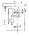
- FIG. 2 shows an embodiment of the coder 22 in sub-bands modified to allow its application in the context of the present invention.
- the encoder 22 firstly comprises a filter bank 30 (FB) cutting the bandwidth of the residual signal in baseband into 12 adjacent sub-bands distributed according to table II below:
- FB filter bank 30
- the filter bank 30 uses quadrature half-band filter cells as described in the IBM Technical Disclosure Bulletin, Vol. 19, No. 9, of February 1977, pages 3438-39.
- each sub-group corresponds to at least one of the possible transmission speeds.
- the highest transmission speed of each subgroup determines the rate of the subgroup's coding bit.
- the device DAB1 processes the sub-bands 2 to 5 grouped into a first sub-group SG1.
- DAB2 calculates the dynamic allocation of 8 additional bits on sub-bands 1 and 6 (added to subgroup SG1 to form the subgroup SG2) for which
- DAB3 calculates the allocation of 7 additional bits on sub-bands 7, 8, 9 (to be added to SG2 to obtain the sub-group SG3)
- DAB4 dynamically allocates 7 additional bits to the sub-bands 10, 11, 12 (to be added to SG3 to obtain the SG4 sub-group).
- the circuits DAB1 to DAB4 have been grouped in FIG. 2 into a dynamic bit allocator 33.
- each of the N (i) calculated must be adjusted to an integer value such that the sum of the N (i) determined by each of the devices DAB1 to DAB4 is equal to the predetermined number chosen. This adjustment is made by the technique already used and described in the references cited above.
- the sum of N (i) for the 12 sub-bands is equal to 30 per macro-sample, i.e. the number of bits, per macro-sample defined for transmission at the highest speed (see table I).
- Dynamic allocations 2400 bps (re) quantization bits (S G O subgroup) have not been described above. We will see later that this transmission speed is treated in a particular way.
- the signal samples are requantified in Q1 to Q4.
- the requantified sample bits are then arranged in a format which will be described based on an example.
- the assembly (31, 33, Q1, Q2, Q3, Q4) therefore groups the sub-bands into sub-groups and requantifies the signals of each sub-band as a function of the sub-group to which said sub-band belongs.
- N (i) is used to regulate the requantification steps of the applicants Q1 to Q4 which process the samples of the subgroups SG1 to SG4 respectively.
- the requantification step Q (i) of the i th sub-band is such that:
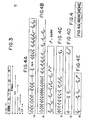
- the bits resulting from the coding of each 20 ms signal segment are distributed by the multiplexer 28 within a frame (see FIG. 3) comprising several zones (F0, Fl, ).
- a block of bits distributed in a multi-frame frame is thus obtained every 20 ms.
- F0, Fl, F2, F3 and F4 there are five zones designated by F0, Fl, F2, F3 and F4.
- a more or less large portion (number of zones) of the multi-unit block or frame will be transmitted.
- PARCOR coefficients are coded in QA2 according to the method described in "Piecewise Linear Quantization of LPC Reflection Coefficients" described by C. Un and S. Yang in the document of the International Conference on Acoustics, Speech and Signal Processing (ICASSP), Hartford 1977, pages 417 to 420. More specifically, 28 bits have been reserved for the PARCOR coefficients (see table I) distributed as follows:
- the bits of the FO zone will be:
- the FO area therefore contains:
- bits are distributed according to the diagram in FIG. 4A representing the area FO of the multi-unit block, that is to say the area corresponding to the transmission speed at 2400 bps.
- the area F1 represented in FIG. 4B contains: and two reserve bits (not used during the subsequent decoding of the signal on reception).
- the area F2 represented in FIG. 4C contains:
- the zone F2 therefore contains the bits of the sub-bands (1 and 6) to be added to the sub-groups corresponding to the immediately lower speed (2400 bps) to form the next sub-group (4800 bps).
- the area F3 represented in FIG. 4D contains:
- This area will also include an additional reserve bit.
- the bits obtained at the output of the quantization devices Q1 to Q4 are multiplexed at 28 according to the multi-rate block format comprising the areas FO to F4.
- a command is applied to the multiplexer 28 via the line CTRL. This command is used to truncate, if necessary, each multi-unit block or frame to the dimensions required before transmission on the line L connected to the multiplexer 28.
- FIG. 5 shows a diagram of a VEPC type receiver similar to that of the prior art (see in particular FIGS. 8 to 11 of European patent 0 002 998) modified for the purposes of the present invention.
- Arri data on the input line L are first demultiplexed at 34 (DMPX).
- the demultiplexer 34 separates the information from the ENERG (E), SIGNAL and COEF (K) channels from each other.
- the SIGNAL information is firstly decoded at 36 (SBC) so as to restore the samples of the residual signal in baseband. These samples are subjected in 36 to inverse quantification operations associated with filtering and interpolation operations intended to recombine the sub-bands into the original base band.
- the filtering is carried out using elements HI 1 and H ' 2 which are high pass and low pass quadrature half-band filters respectively. Interpolation is obtained by inserting a zero between two consecutive input samples. Then add the outputs of the filters taken two by two. For more details, refer to the references cited.
- the baseband signal sampling frequency is reduced to 8 KHz by an interpolator 38 (INT).
- This device calculates the intermediate samples to be placed between two consecutive samples at 4 KHz, the interpolation can be carried out via a filter.
- the path of the signal leaving the interpolator is split into two channels, one direct, the other indirect.
- the indirect channel comprises a high band generator 39 (HB) in which a spreading of the spectrum of the low band is effected, by non-linear distortion at 40 (DISTORT), extractions of the high bands by filtering at 42 and modulation in EAD of the high band used by the energy information supplied by the ENERG channel receiving the energy information E and decoding it at 55 (DEC1).
- HB high band generator 39
- DISTORT non-linear distortion at 40
- the upper limit of the baseband is known (see Table II).
- the high frequency band therefore depends on the transmission speed selected.
- the high pass filter 42 should be chosen accordingly. More precisely, for 2400 and 4800 Bps the passband of the filter 42 is fixed at 750-3400 Hz; for 7200 Bps it is fixed at 875-3400 Hz; for 9600 Bps and 12000 Bps it is respectively fixed at 1250-3400 Hz and 1625-3400 Hz. This is the reason why the filter 42 is constituted by a set of four bandpass filters designated by HP1 to HP4 associated with switches 44 and 46.
- the information on the transmission speed determined for example by applying conventional methods of the SDLC type, is used to choose the filter to be used.
- the filters HP1 to HP4 will be of the transverse type of the same order and will use the same delay line.
- the energy of the signal supplied by the device 40 may be insufficient for the needs of the decoder of the invention.
- a white noise generator 48 (WN).
- the level of this energy must be adjusted so that it performs its functions for low energy sounds in the low frequency band, without disturbing the operation when processing voiced sounds. This requires that the white noise has a low amplitude compared to the energy of the high band of the voiced sounds.
- the WN setting can be done empirically or dynamically.
- the signal resulting from the addition of white noise to the information coming from the device 40 (DISTORT) passes through one of the band pass filters 42 operating the extraction of the high frequency band concerned.
- the samples leaving the filter 42 are introduced into the energy adjustment device 50 (EAD) which normalizes the level of the high band.
- This normalization is obtained by measurement using an ENF device (51) of the energy E'2 of the signal from the filter 42, comparison of E'2 with the energy E'1, where E'1 denotes El and / or E2 from the DEC 1 decoder placed on the ENERG channel conveying the terms E representing the energy in the frequency band 1625-3400 Hz, and finally modulation of the signal from the filter 42 by the result of this comparison.
- the output of the device 50 is added to the output of the interpolator 38 in AD.
- the resulting signal is filtered by a digital filter 52 (INVF) of the trellis type having for coefficients the PARCORS terms supplied by the COEF channel and decoded at 54 (DEC 2).
- delay elements 56 (DL3), 57 (DL4) and 59 (DL6) intended to put the information of said branches in synchronism with each other. to others.
- FIG. 6 shows an embodiment of the circuit 39 (HB) of FIG. 5.
- the information indicating the transmission speed used is used to address a table 64 providing the indication with output of the filter HP1 to HP4 to use. This information controls switches 44 and 46. Table 64 also indicates the value Xbb of the lower frequency of the passband of the filter HP1 to HP4 selected.
- This information is sent in an adjustment circuit 66 also connected to the decoder 55 providing it with a parameter E'1 and to the ENG device 51 supplying it with E'2.
- the adjustment circuit 66 calculates a term a such that
- the term a is used to modulate at 68 the information leaving the filter 42.
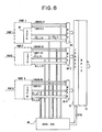
- FIG. 7 the block diagram of a device for serving "L" sources respectively connected to doors designated by PORT1 to PORTL.
- SB1, SB2, ..., SBL are used to designate the filter banks belonging to sub-band coders respectively processing the signals of gates 1 to L, a distribution of sub-band samples is obtained as shown in Figure 7.
- This method has the advantage of providing a dynamic allocation coding means extending optimally to all of the p.L sub-bands. However, it can have some drawbacks when it is desired to apply it to a TASI type system.
- the voice signal supplied by each of the eight sources (not shown) is submitted to an encoder CODE1 to CODE8 through a door (PORT1 to PORT8).
- Coders CODE1 to CODE8 use the principles of sub-band coding with dynamic allocation of coding bits.
- Each coder is of the type shown in FIG. 2. More precisely, the two groups of terms C (i, j) and X (i, j, k) are provided by a coder in sub-bands of the residual signal in base band. SBC type.
- the MPX multiplexer of each coder provides blocks of bits arranged in the multi-channel format described above (see Figure 4).
- An activity controller 68 determines the relative activity of each source and deduces therefrom the transmission speed and therefore the bit rate V (k) to be allocated to said source.
- V (k) when adjusted, define how the multi-bit format blocks corresponding to a block of samples from source (k) are to be truncated. This formatting is carried out in 70.
- the data of the eight coders are multiplexed in MPLX 72 to be transmitted on the LL line.
- Nc is equal to the portion of capacity of the LL channel available for the transmission of the gate macro-samples.
- the formula (23) translates an optimal dynamic distribution of the ML bits intended for coding of the signals between the L gates according to their activities W (k).
- results can be further improved by also taking into account the energies in high frequency band ENERG (k), that is to say the terms E (l, k) and / or E (2, k) and by using
- ⁇ is a numerical coefficient determined empirically and intended to take into account the statistical differences in energy distribution between high frequency bands and low frequency bands of the spectrum of the voice signal.
- the activity controller 68 therefore receives the terms C (i, k) and begins by decoding them by consulting a reverse logarithmic table to that used to code the C (i, k) into C (i, k). This decoding provides terms C (i, k). This same controller 68 also receives the energy information, namely E (l, k) and / or E (2, k) '.
- the operations of the formulas (22 ") and (24) are carried out at 68. They are followed by the execution of the operations of the formula (23 ′) which fixes the bit rate V (k), therefore the transmission speed, to allocate to each source for the signal section with a duration of 20 ms being processed.
- This information makes it possible to truncate, in the device 70, the block of multi-bit bits from each source in order to bring it back to the desired format. of each source are then multiplexed in time in the device 72.
- This device uses in particular the rules of procedure SDLC.
Landscapes
- Engineering & Computer Science (AREA)
- Signal Processing (AREA)
- Human Computer Interaction (AREA)
- Computational Linguistics (AREA)
- Health & Medical Sciences (AREA)
- Audiology, Speech & Language Pathology (AREA)
- Quality & Reliability (AREA)
- Physics & Mathematics (AREA)
- Acoustics & Sound (AREA)
- Multimedia (AREA)
- Computer Networks & Wireless Communication (AREA)
- Compression, Expansion, Code Conversion, And Decoders (AREA)
- Transmission Systems Not Characterized By The Medium Used For Transmission (AREA)
- Time-Division Multiplex Systems (AREA)
- Reduction Or Emphasis Of Bandwidth Of Signals (AREA)
Priority Applications (4)
| Application Number | Priority Date | Filing Date | Title |
|---|---|---|---|
| EP82430012A EP0093219B1 (de) | 1982-04-30 | 1982-04-30 | Digitales Kodierungsverfahren und Anordnung zur Durchführung dieses Verfahrens |
| DE8282430012T DE3270212D1 (en) | 1982-04-30 | 1982-04-30 | Digital coding method and device for carrying out the method |
| JP58044612A JPS58191550A (ja) | 1982-04-30 | 1983-03-18 | 符号化装置 |
| US07/031,152 US4790015A (en) | 1982-04-30 | 1987-03-25 | Multirate digital transmission method and device for implementing said method |
Applications Claiming Priority (1)
| Application Number | Priority Date | Filing Date | Title |
|---|---|---|---|
| EP82430012A EP0093219B1 (de) | 1982-04-30 | 1982-04-30 | Digitales Kodierungsverfahren und Anordnung zur Durchführung dieses Verfahrens |
Publications (2)
| Publication Number | Publication Date |
|---|---|
| EP0093219A1 true EP0093219A1 (de) | 1983-11-09 |
| EP0093219B1 EP0093219B1 (de) | 1986-04-02 |
Family
ID=8189979
Family Applications (1)
| Application Number | Title | Priority Date | Filing Date |
|---|---|---|---|
| EP82430012A Expired EP0093219B1 (de) | 1982-04-30 | 1982-04-30 | Digitales Kodierungsverfahren und Anordnung zur Durchführung dieses Verfahrens |
Country Status (4)
| Country | Link |
|---|---|
| US (1) | US4790015A (de) |
| EP (1) | EP0093219B1 (de) |
| JP (1) | JPS58191550A (de) |
| DE (1) | DE3270212D1 (de) |
Families Citing this family (28)
| Publication number | Priority date | Publication date | Assignee | Title |
|---|---|---|---|---|
| EP0331857B1 (de) * | 1988-03-08 | 1992-05-20 | International Business Machines Corporation | Verfahren und Einrichtung zur Sprachkodierung mit niedriger Datenrate |
| US5068813A (en) * | 1989-11-07 | 1991-11-26 | Mts Systems Corporation | Phased digital filtering in multichannel environment |
| CA2032765C (en) * | 1989-12-21 | 1995-12-12 | Hidetaka Yoshikawa | Variable rate encoding and communicating apparatus |
| US5502789A (en) * | 1990-03-07 | 1996-03-26 | Sony Corporation | Apparatus for encoding digital data with reduction of perceptible noise |
| FR2669168B1 (fr) * | 1990-11-09 | 1993-04-23 | Abiven Jacques | Procede de multiplexage-demultiplexage numerique multidebit. |
| FI90297C (fi) * | 1992-04-02 | 1994-01-10 | Nokia Telecommunications Oy | Digitaalisen siirtoverkon verkkoliitäntämenetelmä ja verkkoliitäntä |
| JPH06197084A (ja) * | 1992-12-25 | 1994-07-15 | Takayama:Kk | 音声転送方法 |
| JPH07123242B2 (ja) * | 1993-07-06 | 1995-12-25 | 日本電気株式会社 | 音声信号復号化装置 |
| US6134521A (en) * | 1994-02-17 | 2000-10-17 | Motorola, Inc. | Method and apparatus for mitigating audio degradation in a communication system |
| US5734677A (en) * | 1995-03-15 | 1998-03-31 | The Chinese University Of Hong Kong | Method for compression of loss-tolerant video image data from multiple sources |
| JP3637661B2 (ja) * | 1995-12-19 | 2005-04-13 | ソニー株式会社 | 端末装置及び送信方法 |
| US6111870A (en) | 1996-11-07 | 2000-08-29 | Interdigital Technology Corporation | Method and apparatus for compressing and transmitting high speed data |
| KR100548891B1 (ko) | 1998-06-15 | 2006-02-02 | 마츠시타 덴끼 산교 가부시키가이샤 | 음성 부호화 장치 및 음성 부호화 방법 |
| FR2781944B1 (fr) * | 1998-07-29 | 2001-10-05 | Inst Francais Du Petrole | Methode pour realiser une compression sans pertes de signaux a grande dynamique en vue de leur transmission |
| FR2822322A1 (fr) * | 2001-03-13 | 2002-09-20 | Koninkl Philips Electronics Nv | Modulateur numerique |
| US6920471B2 (en) * | 2002-04-16 | 2005-07-19 | Texas Instruments Incorporated | Compensation scheme for reducing delay in a digital impedance matching circuit to improve return loss |
| US7650277B2 (en) * | 2003-01-23 | 2010-01-19 | Ittiam Systems (P) Ltd. | System, method, and apparatus for fast quantization in perceptual audio coders |
| US7016409B2 (en) * | 2003-11-12 | 2006-03-21 | Sony Corporation | Apparatus and method for use in providing dynamic bit rate encoding |
| WO2006138232A2 (en) * | 2005-06-13 | 2006-12-28 | Tvi Corporation | Collapsible patient isolation pod |
| FI20065474L (fi) * | 2006-07-04 | 2008-01-05 | Head Inhimillinen Tekijae Oy | Menetelmä ääni-informaation käsittelemiseksi |
| US8521540B2 (en) * | 2007-08-17 | 2013-08-27 | Qualcomm Incorporated | Encoding and/or decoding digital signals using a permutation value |
| CN103544957B (zh) * | 2012-07-13 | 2017-04-12 | 华为技术有限公司 | 音频信号的比特分配的方法和装置 |
| US9391575B1 (en) * | 2013-12-13 | 2016-07-12 | Amazon Technologies, Inc. | Adaptive loudness control |
| US11714127B2 (en) | 2018-06-12 | 2023-08-01 | International Business Machines Corporation | On-chip spread spectrum characterization |
| US11146307B1 (en) * | 2020-04-13 | 2021-10-12 | International Business Machines Corporation | Detecting distortion in spread spectrum signals |
| CN113539231B (zh) | 2020-12-30 | 2024-06-18 | 腾讯科技(深圳)有限公司 | 音频处理方法、声码器、装置、设备及存储介质 |
| US11693446B2 (en) | 2021-10-20 | 2023-07-04 | International Business Machines Corporation | On-chip spread spectrum synchronization between spread spectrum sources |
| US12255671B2 (en) * | 2023-03-16 | 2025-03-18 | International Business Machines Corporation | Separable, intelligible, single channel voice communication |
Citations (3)
| Publication number | Priority date | Publication date | Assignee | Title |
|---|---|---|---|---|
| US3437761A (en) * | 1963-11-26 | 1969-04-08 | Philco Ford Corp | Speech apparatus which produces a timemultiplex signal having an interlace pattern |
| FR2389277A1 (fr) * | 1977-04-29 | 1978-11-24 | Ibm France | Procede de quantification a allocation dynamique du taux de bits disponible, et dispositif de mise en oeuvre dudit procede |
| EP0002998A1 (de) * | 1977-12-23 | 1979-07-11 | International Business Machines Corporation | Verfahren und Vorrichtung zur Sprachdatenkompression |
Family Cites Families (7)
| Publication number | Priority date | Publication date | Assignee | Title |
|---|---|---|---|---|
| NL7600932A (nl) * | 1976-01-30 | 1977-08-02 | Philips Nv | Bandcompressie systeem. |
| GB1559897A (en) * | 1977-03-15 | 1980-01-30 | Post Office | Multiplexing speech |
| US4310922A (en) * | 1980-01-10 | 1982-01-12 | Lichtenberger W Wayne | Bit sampling multiplexer apparatus |
| US4330689A (en) * | 1980-01-28 | 1982-05-18 | The United States Of America As Represented By The Secretary Of The Navy | Multirate digital voice communication processor |
| IT1144551B (it) * | 1981-02-24 | 1986-10-29 | Cselt Centro Studi Lab Telecom | Dispositivo numerico per la discriminazione di segnali vocali e segnali dati entrambi numerizzati |
| DE3167257D1 (en) * | 1981-02-27 | 1985-01-03 | Ibm | Transmission methods and apparatus for implementing the method |
| EP0085820B1 (de) * | 1982-02-09 | 1985-11-21 | International Business Machines Corporation | Verfahren zur digitalen Übertragung mit mehreren Geschwindigkeiten und Einrichtung zur Ausführung dieses Verfahrens |
-
1982
- 1982-04-30 DE DE8282430012T patent/DE3270212D1/de not_active Expired
- 1982-04-30 EP EP82430012A patent/EP0093219B1/de not_active Expired
-
1983
- 1983-03-18 JP JP58044612A patent/JPS58191550A/ja active Granted
-
1987
- 1987-03-25 US US07/031,152 patent/US4790015A/en not_active Expired - Fee Related
Patent Citations (3)
| Publication number | Priority date | Publication date | Assignee | Title |
|---|---|---|---|---|
| US3437761A (en) * | 1963-11-26 | 1969-04-08 | Philco Ford Corp | Speech apparatus which produces a timemultiplex signal having an interlace pattern |
| FR2389277A1 (fr) * | 1977-04-29 | 1978-11-24 | Ibm France | Procede de quantification a allocation dynamique du taux de bits disponible, et dispositif de mise en oeuvre dudit procede |
| EP0002998A1 (de) * | 1977-12-23 | 1979-07-11 | International Business Machines Corporation | Verfahren und Vorrichtung zur Sprachdatenkompression |
Non-Patent Citations (5)
| Title |
|---|
| CONFERENCE RECORD OF THE 1978 IEEE INTERNATIONAL CONFERENCE ON ACUSTICS, SPEECH AND SIGNAL PROCESSING, 10-12 avril 1978, pages 307-311, New York (USA); * |
| CONFERENCE RECORD OF THE 1978 IEEE INTERNATIONAL CONFERENCE ON ACUSTICS, SPEECH AND SIGNAL PROCESSING, 10-12 avril 1978, pages 320-325, New York (USA); * |
| CONFERENCE RECORD OF THE 1978 IEEE INTERNATIONAL CONFERENCE ON ACUSTICS, SPEECH AND SIGNAL PROCESSING; * |
| PROCEEDINGS OF THE 1974 INTERNATIONAL ZURICH SEMINAR ON DIGITAL COMMUNICATIONS, 12-15 mars 1974, pages B1(1) to B1(4), New York (USA); * |
| THE BELL SYSTEM TECHNICAL JOURNAL, vol. 58, no. 3, mars 1979, pages 577-600, New York (USA); * |
Also Published As
| Publication number | Publication date |
|---|---|
| JPS58191550A (ja) | 1983-11-08 |
| DE3270212D1 (en) | 1986-05-07 |
| JPH0140537B2 (de) | 1989-08-29 |
| EP0093219B1 (de) | 1986-04-02 |
| US4790015A (en) | 1988-12-06 |
Similar Documents
| Publication | Publication Date | Title |
|---|---|---|
| EP0093219B1 (de) | Digitales Kodierungsverfahren und Anordnung zur Durchführung dieses Verfahrens | |
| EP0085820B1 (de) | Verfahren zur digitalen Übertragung mit mehreren Geschwindigkeiten und Einrichtung zur Ausführung dieses Verfahrens | |
| EP0111612B1 (de) | Verfahren und Einrichtung zur Kodierung eines Sprachsignals | |
| EP0064119B1 (de) | Sprachkodierungsverfahren und Einrichtung zur Durchführung des Verfahrens | |
| EP0002998B1 (de) | Verfahren und Vorrichtung zur Sprachdatenkompression | |
| EP0127718B1 (de) | Verfahren zur Aktivitätsdetektion in einem Sprachübertragungssystem | |
| Tribolet et al. | A study of complexity and quality of speech waveform coders | |
| EP0768770B1 (de) | Verfahren und Vorrichtung zur Erzeugung von Hintergrundrauschen in einem digitalen Übertragungssystem | |
| EP0059294B1 (de) | Übertragungsverfahren und Einrichtung zur Ausführung des Verfahrens | |
| KR100242864B1 (ko) | 디지탈 신호 부호화 장치 및 방법 | |
| EP2277172B1 (de) | Verbergung von übertragungsfehlern in einem digitalsignal in einer hierarchischen decodierungsstruktur | |
| JPH0748697B2 (ja) | 信号のディジタル・ブロック・コ−ド化方法 | |
| JPH0243382B2 (de) | ||
| EP0070949A1 (de) | Übertragungsverfahren für Sprache und digitale Daten und Ausführungsanordnung für das genannte Verfahren | |
| WO2014154988A1 (fr) | Mixage partiel optimisé de flux audio codés selon un codage par sous-bandes | |
| WO2002063609A1 (fr) | Methode et dispositif de traitement d'une pluralite de flux binaires audio | |
| EP2171713B1 (de) | Kodierung digitaler audiosignale | |
| EP2979437B1 (de) | Optimiertes mischen von durch subband-codierung codierten audioströmen | |
| EP0891617B1 (de) | System zur kodierung und dekodierung eines signals, insbesondere eines digitalen audiosignals | |
| FR2859566A1 (fr) | Procede de transmission d'un flux d'information par insertion a l'interieur d'un flux de donnees de parole, et codec parametrique pour sa mise en oeuvre | |
| WO2007006958A2 (fr) | Procédé et dispositif d'atténuation des échos d'un signal audionumérioue issu d'un codeur multicouches | |
| Kou et al. | Digital speech interpolation for variable rate coders with application to subband coding | |
| EP0124411A1 (de) | Kanalvocoder mit Vorrichtung zur Unterdrückung von Störmodulation der synthetisierden Sprache | |
| JPH11145846A (ja) | 信号圧縮伸張装置及び方法 | |
| FR2749723A1 (fr) | Procede et dispositif de codage en compression d'un signal numerique |
Legal Events
| Date | Code | Title | Description |
|---|---|---|---|
| PUAI | Public reference made under article 153(3) epc to a published international application that has entered the european phase |
Free format text: ORIGINAL CODE: 0009012 |
|
| AK | Designated contracting states |
Designated state(s): DE FR GB |
|
| 17P | Request for examination filed |
Effective date: 19840218 |
|
| GRAA | (expected) grant |
Free format text: ORIGINAL CODE: 0009210 |
|
| AK | Designated contracting states |
Kind code of ref document: B1 Designated state(s): DE FR GB |
|
| REF | Corresponds to: |
Ref document number: 3270212 Country of ref document: DE Date of ref document: 19860507 |
|
| PLBE | No opposition filed within time limit |
Free format text: ORIGINAL CODE: 0009261 |
|
| STAA | Information on the status of an ep patent application or granted ep patent |
Free format text: STATUS: NO OPPOSITION FILED WITHIN TIME LIMIT |
|
| 26N | No opposition filed | ||
| PGFP | Annual fee paid to national office [announced via postgrant information from national office to epo] |
Ref country code: GB Payment date: 19990330 Year of fee payment: 18 |
|
| PGFP | Annual fee paid to national office [announced via postgrant information from national office to epo] |
Ref country code: FR Payment date: 19990415 Year of fee payment: 18 |
|
| PGFP | Annual fee paid to national office [announced via postgrant information from national office to epo] |
Ref country code: DE Payment date: 19990421 Year of fee payment: 18 |
|
| PG25 | Lapsed in a contracting state [announced via postgrant information from national office to epo] |
Ref country code: GB Free format text: LAPSE BECAUSE OF NON-PAYMENT OF DUE FEES Effective date: 20000430 |
|
| GBPC | Gb: european patent ceased through non-payment of renewal fee |
Effective date: 20000430 |
|
| PG25 | Lapsed in a contracting state [announced via postgrant information from national office to epo] |
Ref country code: FR Free format text: LAPSE BECAUSE OF NON-PAYMENT OF DUE FEES Effective date: 20001229 |
|
| PG25 | Lapsed in a contracting state [announced via postgrant information from national office to epo] |
Ref country code: DE Free format text: LAPSE BECAUSE OF NON-PAYMENT OF DUE FEES Effective date: 20010201 |
|
| REG | Reference to a national code |
Ref country code: FR Ref legal event code: ST |