EP0093322B1 - Déclencheur à impulsion réagissant à l'usure avancée du frotteur en charbon de prises de courant formant partie de lignes à frottement - Google Patents
Déclencheur à impulsion réagissant à l'usure avancée du frotteur en charbon de prises de courant formant partie de lignes à frottement Download PDFInfo
- Publication number
- EP0093322B1 EP0093322B1 EP83103842A EP83103842A EP0093322B1 EP 0093322 B1 EP0093322 B1 EP 0093322B1 EP 83103842 A EP83103842 A EP 83103842A EP 83103842 A EP83103842 A EP 83103842A EP 0093322 B1 EP0093322 B1 EP 0093322B1
- Authority
- EP
- European Patent Office
- Prior art keywords
- shaft
- contact
- sliding
- contact line
- current collectors
- Prior art date
- Legal status (The legal status is an assumption and is not a legal conclusion. Google has not performed a legal analysis and makes no representation as to the accuracy of the status listed.)
- Expired - Lifetime
Links
- OKTJSMMVPCPJKN-UHFFFAOYSA-N Carbon Chemical compound [C] OKTJSMMVPCPJKN-UHFFFAOYSA-N 0.000 title claims abstract description 17
- 229910052799 carbon Inorganic materials 0.000 title claims abstract description 17
- 239000004020 conductor Substances 0.000 description 28
- 230000001960 triggered effect Effects 0.000 description 2
- 230000005540 biological transmission Effects 0.000 description 1
- 239000003245 coal Substances 0.000 description 1
- 238000010276 construction Methods 0.000 description 1
- 238000006073 displacement reaction Methods 0.000 description 1
- 238000012423 maintenance Methods 0.000 description 1
- 238000012544 monitoring process Methods 0.000 description 1
- 210000003462 vein Anatomy 0.000 description 1
Images
Classifications
-
- B—PERFORMING OPERATIONS; TRANSPORTING
- B60—VEHICLES IN GENERAL
- B60M—POWER SUPPLY LINES, AND DEVICES ALONG RAILS, FOR ELECTRICALLY- PROPELLED VEHICLES
- B60M1/00—Power supply lines for contact with collector on vehicle
- B60M1/02—Details
-
- B—PERFORMING OPERATIONS; TRANSPORTING
- B60—VEHICLES IN GENERAL
- B60M—POWER SUPPLY LINES, AND DEVICES ALONG RAILS, FOR ELECTRICALLY- PROPELLED VEHICLES
- B60M7/00—Power lines or rails specially adapted for electrically-propelled vehicles of special types, e.g. suspension tramway, ropeway, underground railway
Definitions
- the invention relates to a pulse trigger responsive to the advanced wear of the carbon brushes of current collectors forming part of multi-core conductor lines.
- a known pulse trigger (US-A-2,700,760) has a pair of one-armed levers, which each enclose a core of the conductor rail on an axis extending transversely to the conductor rail on the rear side of the conductor rail, with the lower edge of the lever extending in the running direction of the pantograph the action of a return spring on the levers is brought to a level which is below the level to which the pantograph body extends when the abrasive carbon is worn out, and in the event of advanced wear of the abrasive carbon and the corresponding displacement of the pantograph towards the wire with its body running onto the levers this is pivoted in the direction of the vein with the triggering of contact.
- the invention has for its object to solve the problem of the advanced wear of the carbon brushes of pantographs forming part of conductor rails via a pulse trigger in a structurally simpler manner, which then also makes it possible to multi-core the pulse trigger Assign conductor lines, the wires of which run at a comparatively small distance from each other.
- the pulse trigger installed on the conductor rail is run over by a pantograph with largely worn carbon brush
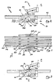
- the stop located on the pantograph and accordingly displaced against the conductor rail runs against the corresponding, on the conductor line projecting lever on the shaft forming part of the pulse trigger, whereby the shaft is imparted a rotary movement by which the actuator still sitting on the shaft interacts with a switch and thus triggers a pulse that either leads to one Maintenance personnel informative signal leads or causes a switch provided in the monorail behind the pulse trigger is operated, through which the monorail vehicle with worn carbon brushes gets onto a repair track, in which it is then ready to replace the coal.
- This pulse trigger can be easily assigned to multi-conductor conductor lines, the conductors of which are at a comparatively short distance from one another.
- the solution according to the invention is a comparatively simple and, accordingly, inexpensive construction.
- one single signal line for indicating the wear of the carbon brushes of one of several pantographs is also advantageous.
- the conductor line 11/12 shown in FIG. 1 is a 4-pole contact-protected conductor line.
- the busbars 111, 111 '... are arranged in the base of plastic channels 112, 112' ... which are designed in such a way that the busbars 111, 111 '... are only for the carbon which forms part of the current collectors 21 (FIGS. 2 and 3) 211 are accessible.
- the 4 cores of the conductor line 11/12 are summarized, for example, by crossbars, not shown, on which the cores are fixed at a defined distance from one another by means of brackets forming part of the crossbars and engaging the plastic channels 112, 112 '.
- a shaft 311 (312, 312 ') extending transversely to the conductor rail is mounted below the conductor rail 11/12, on which on the one hand levers 313, 313' .. extend between the plastic channels 112, 112 '... of the conductor rail 11/12. and on the other hand, on the shaft ends 311 'projecting beyond the bearing 312', a cam 316 actuating a switch 316 is seated.
- the levers 313, 313 '... located on the shaft 311 extend between the plastic channels 112, 112' ... forming the component of the conductor line 11/12 and protrude to a limited extent from the conductor line 11/12 on the current collector side (21).
- the closing contact 3161 of the switch 316 which is supported by a roller 3162 on the cam disk 314 forming part of the shaft 311, is open.
- the pulse or signal trigger 31 is triggered by the pantographs 21 ... which move in the direction of arrow A and which protrude via the respective plastic channel 112, 112 '... Ausatz 212 are provided, run over without active intervention. If the wear of the carbon brush 211 of one or more pantographs 21 ... has progressed and the pantograph 21 has lowered accordingly (arrow B), the cutout 212 comes to the respective pantographs 21 ... with the protruding parts over the conductor line 11/12, Part of the trigger 31 forming, on the shaft 311 seated lever 313,313 '...
- the pulse trigger 31 is combined in a housing 41, which is connected to the conductor line 11/12 via brackets 411, 411 '.
- the switch 316 from which lines 3163, 3163 'originate, is then also installed in the housing 41.
Landscapes
- Engineering & Computer Science (AREA)
- Mechanical Engineering (AREA)
- Current-Collector Devices For Electrically Propelled Vehicles (AREA)
- Contacts (AREA)
- Electrical Discharge Machining, Electrochemical Machining, And Combined Machining (AREA)
- Pressure Welding/Diffusion-Bonding (AREA)
Claims (4)
- Déclencheur d'impulsion (31) réagissant à la progression de l'usure des charbons de balai de capteurs de courant (21) déplaçables le long d'une ligne de contact à conducteurs multiples (11,12), présentant les caractéristiques suivantes :1. il est prévu un arbre (331) passant transversalement la largeur de la ligne de contact (11,12), sur sa face arrière,2. en partant de l'arbre (311), des leviers (313) faisant saillie sur la face arrière de la ligne de contact (11,12) partent chaque fois, adjacent à un conducteur (111/112, 111'/112'...) de la ligne de contact, l'arbre (311) étant en position initiale,3. un ressort de rappel (317) agit sur l'arbre (311), en déterminant la position initiale de ce dernier,4. chacun des capteurs de courant (21) est pourvu d'un appendice (212), faisant saillie latéralement du capteur, produisant un mouvement de rotation, lorsque le charbon de balai est usé, en passant contre le levier (313) partant de l'arbre (311),5. l'arbre (311) est pourvu d'un prolongement (311') au-dessus de la ligne de contact (11,12), sur lequel est disposé un organe d'actionnement (314) qui actionne un interrupteur (316) lors de la rotation de l'arbre (311) lui faisant quitter sa position initiale.
- Déclencheur d'impulsion selon la revendication 1, caractérisé en ce que l'organe d'actionnement est un disque de came (314) se trouvant à une extrémité de l'arbre (311), sur lequel prend appui une languette de contact élastique (3161) faisant partie de l'interrupteur (316).
- Déclencheur d'impulsion selon la revendication 2, caractérisé en ce que la languette de contact (3161) prend appui sur le disque de came (314) par l'intermédiaire d'un galet (3162) disposé à l'extrémité libre de la languette de contact (3161).
- Déclencheur d'impulsion selon l'une des revendications 1 à 3, caractérisé en ce que l'arbre (311) est monté dans un carter (41), disposé sur la ligne de contact (11,12), dans lequel est également installé l'interrupteur (316).
Priority Applications (1)
| Application Number | Priority Date | Filing Date | Title |
|---|---|---|---|
| AT83103842T ATE65220T1 (de) | 1982-04-23 | 1983-04-20 | Auf die fortgeschrittene abnutzung der schleifkohle von bestandteil von schleifleitungen bildenden stromabnehmern ansprechender impulsausloeser. |
Applications Claiming Priority (2)
| Application Number | Priority Date | Filing Date | Title |
|---|---|---|---|
| DE3215251 | 1982-04-23 | ||
| DE3215251A DE3215251C2 (de) | 1982-04-23 | 1982-04-23 | Auf die fortgeschrittene Abnutzung der Schleifkohle von Bestandteil von Schleifleitungen bildenden Stromabnehmern ansprechender Impulsauslöser |
Publications (3)
| Publication Number | Publication Date |
|---|---|
| EP0093322A2 EP0093322A2 (fr) | 1983-11-09 |
| EP0093322A3 EP0093322A3 (en) | 1987-05-06 |
| EP0093322B1 true EP0093322B1 (fr) | 1991-07-17 |
Family
ID=6161797
Family Applications (1)
| Application Number | Title | Priority Date | Filing Date |
|---|---|---|---|
| EP83103842A Expired - Lifetime EP0093322B1 (fr) | 1982-04-23 | 1983-04-20 | Déclencheur à impulsion réagissant à l'usure avancée du frotteur en charbon de prises de courant formant partie de lignes à frottement |
Country Status (3)
| Country | Link |
|---|---|
| EP (1) | EP0093322B1 (fr) |
| AT (1) | ATE65220T1 (fr) |
| DE (1) | DE3215251C2 (fr) |
Cited By (1)
| Publication number | Priority date | Publication date | Assignee | Title |
|---|---|---|---|---|
| CN110518753A (zh) * | 2019-10-22 | 2019-11-29 | 广东电网有限责任公司 | 一种应用在集电变电站发电源的集电器组件 |
Families Citing this family (13)
| Publication number | Priority date | Publication date | Assignee | Title |
|---|---|---|---|---|
| DE3701643A1 (de) * | 1987-01-21 | 1988-08-04 | Still Gmbh | Meldeeinrichtung fuer das melden des verschleisszustandes von buersten einer elektrischen maschine |
| DE4413538C2 (de) * | 1994-04-15 | 1997-03-13 | Mannesmann Ag | Energie- und Signalzufuhr für ein Regalbediengerät |
| US10110795B2 (en) | 2002-06-04 | 2018-10-23 | General Electric Company | Video system and method for data communication |
| US20150235094A1 (en) | 2014-02-17 | 2015-08-20 | General Electric Company | Vehicle imaging system and method |
| US9875414B2 (en) | 2014-04-15 | 2018-01-23 | General Electric Company | Route damage prediction system and method |
| US9873442B2 (en) | 2002-06-04 | 2018-01-23 | General Electric Company | Aerial camera system and method for identifying route-related hazards |
| US9919723B2 (en) | 2002-06-04 | 2018-03-20 | General Electric Company | Aerial camera system and method for determining size parameters of vehicle systems |
| US11124207B2 (en) | 2014-03-18 | 2021-09-21 | Transportation Ip Holdings, Llc | Optical route examination system and method |
| DE102017115748B3 (de) | 2017-07-13 | 2018-12-27 | Conductix-Wampfler Gmbh | Vorrichtung zur Detektion eines Abnutzungszustandes eines Schleifkontaktes |
| DE102017115744A1 (de) | 2017-07-13 | 2019-01-17 | Conductix-Wampfler Gmbh | Vorrichtung und Verfahren zur Erkennung des Verschleißes eines Schleifkontaktes und Schleifleitungssystem |
| DE202017104182U1 (de) | 2017-07-13 | 2018-10-17 | Conductix-Wampfler Gmbh | Vorrichtung zur Erkennung des Verschleißes eines Schleifkontaktes und Schleifleitungssystem |
| DE102018125477A1 (de) * | 2018-10-15 | 2020-04-16 | Paul Vahle Gmbh & Co. Kg | Stromabnehmer mit Anzeigeelement zur optischen Kontrolle der Lage des Armes relativ zum Befestigungselement |
| DE102024107807A1 (de) * | 2024-03-19 | 2025-09-25 | Paul Vahle Gmbh & Co. Kg | Kohleverschleißtester |
Family Cites Families (4)
| Publication number | Priority date | Publication date | Assignee | Title |
|---|---|---|---|---|
| US2700760A (en) * | 1951-04-28 | 1955-01-25 | Cheatham Electric Switching Device Co | Detector for worn carbon inserts |
| US3867593A (en) * | 1973-11-07 | 1975-02-18 | Diebold Inc | Pneumatic tube carrier detector assembly with cam operated microswitch and resilient finger heeler means |
| DE2835103A1 (de) * | 1978-08-10 | 1980-02-21 | Graf Armin | Transportvorrichtung |
| DE3013758A1 (de) * | 1980-04-10 | 1981-10-15 | Kollektra Metall- und Kunststoff-Werk GmbH, 6301 Wettenberg | Buersten-stromzufuehrung fuer elektrische maschinen und geraete |
-
1982
- 1982-04-23 DE DE3215251A patent/DE3215251C2/de not_active Expired
-
1983
- 1983-04-20 EP EP83103842A patent/EP0093322B1/fr not_active Expired - Lifetime
- 1983-04-20 AT AT83103842T patent/ATE65220T1/de not_active IP Right Cessation
Cited By (2)
| Publication number | Priority date | Publication date | Assignee | Title |
|---|---|---|---|---|
| CN110518753A (zh) * | 2019-10-22 | 2019-11-29 | 广东电网有限责任公司 | 一种应用在集电变电站发电源的集电器组件 |
| CN110518753B (zh) * | 2019-10-22 | 2020-02-07 | 广东电网有限责任公司 | 一种应用在集电变电站发电源的集电器组件 |
Also Published As
| Publication number | Publication date |
|---|---|
| ATE65220T1 (de) | 1991-08-15 |
| EP0093322A2 (fr) | 1983-11-09 |
| DE3215251A1 (de) | 1983-11-10 |
| DE3215251C2 (de) | 1984-02-16 |
| EP0093322A3 (en) | 1987-05-06 |
Similar Documents
| Publication | Publication Date | Title |
|---|---|---|
| DE3215251C2 (de) | Auf die fortgeschrittene Abnutzung der Schleifkohle von Bestandteil von Schleifleitungen bildenden Stromabnehmern ansprechender Impulsauslöser | |
| DE3541287C2 (fr) | ||
| DE102017115748B3 (de) | Vorrichtung zur Detektion eines Abnutzungszustandes eines Schleifkontaktes | |
| EP3841641B1 (fr) | Transmetteur à bague collectrice | |
| DE1097869B (de) | Fadenwaechter | |
| DE8211804U1 (de) | Auf die fortgeschrittene Abnutzung der Schleifkohle von Bestandteil von Schleifleitungen bildenden Stromabnehmern ansprechender Impulsauslöser | |
| EP0195830B1 (fr) | Dispositif à contact électrique pour un système de sécurité anti-choc à sac gonflable pour véhicules automobiles | |
| DE690175C (de) | Fahrzeug fuer elektrische Spielzeugeisenbahnen mit Fernsteuerung mittels eines durch Stromstoesse beeinflussten Schaltmagneten | |
| EP0360197B1 (fr) | Porte-balais | |
| DE202017104184U1 (de) | Vorrichtung zur Detektion eines Abnutzungszustandes eines Schleifkontakts | |
| DE3504881C2 (fr) | ||
| DE1127459B (de) | Buerstenhalter fuer dynamoelektrische Maschinen | |
| DE2024271A1 (de) | Vorrichtung zum automatischen Ein schalten der Transportmittel an Vorsteckein richtungen für Schreib , Buchungs und ahnl Maschinen | |
| DE2322956A1 (de) | Schutzanordnung fuer elektrofahrzeuge | |
| DE2145312C3 (de) | Elektrischer Hebelschalter | |
| DE641058C (de) | Waehler fuer Fernmeldeanlagen | |
| DE2338508A1 (de) | Grenzgeschwindigkeitsfuehler fuer einen aufzug | |
| DE3235597C2 (fr) | ||
| DE119152C (fr) | ||
| DE2338978C3 (de) | Lenkstockschalter für Fahrzeuge, Insbesondere Kraftfahrzeuge | |
| DE2553779C3 (de) | Lasttrennschalter | |
| AT56410B (de) | Einrichtung zum selbsttätigen Verhindern des Zusammenstoßens von Kraftfahrzuegen, besonders Eisenbahnzügen. | |
| DE4406734A1 (de) | Vorrichtung zur Signalübertragung zwischen zwei Endstellen | |
| DE2621411B2 (de) | Mitnehmereinrichtung für Schleppkreisförderer mit Nebenkreisen | |
| DE2257585B2 (de) | Magnetkopf fuer magnettongeraete, bzw. -speicher |
Legal Events
| Date | Code | Title | Description |
|---|---|---|---|
| PUAI | Public reference made under article 153(3) epc to a published international application that has entered the european phase |
Free format text: ORIGINAL CODE: 0009012 |
|
| AK | Designated contracting states |
Designated state(s): AT BE CH FR GB IT LI LU NL SE |
|
| PUAL | Search report despatched |
Free format text: ORIGINAL CODE: 0009013 |
|
| AK | Designated contracting states |
Kind code of ref document: A3 Designated state(s): AT BE CH FR GB IT LI LU NL SE |
|
| 17P | Request for examination filed |
Effective date: 19871016 |
|
| 17Q | First examination report despatched |
Effective date: 19881004 |
|
| GRAA | (expected) grant |
Free format text: ORIGINAL CODE: 0009210 |
|
| AK | Designated contracting states |
Kind code of ref document: B1 Designated state(s): AT BE CH FR GB IT LI LU NL SE |
|
| PG25 | Lapsed in a contracting state [announced via postgrant information from national office to epo] |
Ref country code: SE Effective date: 19910717 Ref country code: NL Effective date: 19910717 |
|
| REF | Corresponds to: |
Ref document number: 65220 Country of ref document: AT Date of ref document: 19910815 Kind code of ref document: T |
|
| ITF | It: translation for a ep patent filed | ||
| ET | Fr: translation filed | ||
| GBT | Gb: translation of ep patent filed (gb section 77(6)(a)/1977) | ||
| NLV1 | Nl: lapsed or annulled due to failure to fulfill the requirements of art. 29p and 29m of the patents act | ||
| PLBE | No opposition filed within time limit |
Free format text: ORIGINAL CODE: 0009261 |
|
| STAA | Information on the status of an ep patent application or granted ep patent |
Free format text: STATUS: NO OPPOSITION FILED WITHIN TIME LIMIT |
|
| 26N | No opposition filed | ||
| PGFP | Annual fee paid to national office [announced via postgrant information from national office to epo] |
Ref country code: GB Payment date: 19930308 Year of fee payment: 11 |
|
| PGFP | Annual fee paid to national office [announced via postgrant information from national office to epo] |
Ref country code: CH Payment date: 19930311 Year of fee payment: 11 |
|
| PGFP | Annual fee paid to national office [announced via postgrant information from national office to epo] |
Ref country code: LU Payment date: 19930323 Year of fee payment: 11 |
|
| PGFP | Annual fee paid to national office [announced via postgrant information from national office to epo] |
Ref country code: BE Payment date: 19930330 Year of fee payment: 11 |
|
| PGFP | Annual fee paid to national office [announced via postgrant information from national office to epo] |
Ref country code: FR Payment date: 19930331 Year of fee payment: 11 |
|
| PGFP | Annual fee paid to national office [announced via postgrant information from national office to epo] |
Ref country code: AT Payment date: 19930423 Year of fee payment: 11 |
|
| EPTA | Lu: last paid annual fee | ||
| PG25 | Lapsed in a contracting state [announced via postgrant information from national office to epo] |
Ref country code: LU Free format text: LAPSE BECAUSE OF NON-PAYMENT OF DUE FEES Effective date: 19940420 Ref country code: GB Effective date: 19940420 Ref country code: AT Effective date: 19940420 |
|
| PG25 | Lapsed in a contracting state [announced via postgrant information from national office to epo] |
Ref country code: LI Effective date: 19940430 Ref country code: CH Effective date: 19940430 Ref country code: BE Effective date: 19940430 |
|
| BERE | Be: lapsed |
Owner name: PAUL VAHLE G.M.B.H. & CO. K.G. Effective date: 19940430 |
|
| GBPC | Gb: european patent ceased through non-payment of renewal fee |
Effective date: 19940420 |
|
| PG25 | Lapsed in a contracting state [announced via postgrant information from national office to epo] |
Ref country code: FR Effective date: 19941229 |
|
| REG | Reference to a national code |
Ref country code: CH Ref legal event code: PL |
|
| REG | Reference to a national code |
Ref country code: FR Ref legal event code: ST |