EP0093327A2 - Interrupteur électrique rotatif - Google Patents
Interrupteur électrique rotatif Download PDFInfo
- Publication number
- EP0093327A2 EP0093327A2 EP83103855A EP83103855A EP0093327A2 EP 0093327 A2 EP0093327 A2 EP 0093327A2 EP 83103855 A EP83103855 A EP 83103855A EP 83103855 A EP83103855 A EP 83103855A EP 0093327 A2 EP0093327 A2 EP 0093327A2
- Authority
- EP
- European Patent Office
- Prior art keywords
- contact
- contact spring
- housing
- rotary switch
- switch
- Prior art date
- Legal status (The legal status is an assumption and is not a legal conclusion. Google has not performed a legal analysis and makes no representation as to the accuracy of the status listed.)
- Granted
Links
Images

Classifications
-
- H—ELECTRICITY
- H01—ELECTRIC ELEMENTS
- H01H—ELECTRIC SWITCHES; RELAYS; SELECTORS; EMERGENCY PROTECTIVE DEVICES
- H01H19/00—Switches operated by an operating part which is rotatable about a longitudinal axis thereof and which is acted upon directly by a solid body external to the switch, e.g. by a hand
- H01H19/02—Details
- H01H19/10—Movable parts; Contacts mounted thereon
- H01H19/11—Movable parts; Contacts mounted thereon with indexing means
-
- H—ELECTRICITY
- H01—ELECTRIC ELEMENTS
- H01H—ELECTRIC SWITCHES; RELAYS; SELECTORS; EMERGENCY PROTECTIVE DEVICES
- H01H19/00—Switches operated by an operating part which is rotatable about a longitudinal axis thereof and which is acted upon directly by a solid body external to the switch, e.g. by a hand
- H01H19/54—Switches operated by an operating part which is rotatable about a longitudinal axis thereof and which is acted upon directly by a solid body external to the switch, e.g. by a hand the operating part having at least five or an unspecified number of operative positions
- H01H19/60—Angularly-movable actuating part carrying no contacts
- H01H19/63—Contacts actuated by axial cams
Definitions
- the innovation is based on an electric rotary switch according to the preamble of claim 1.
- Such rotary switches are used both as individual switches and as add-on switches, e.g. used as a so-called battery switch, in module systems for rotary resistors, in the latter application they can be actuated by means of the shaft of the associated rotary resistor.
- DE-PS 28 32 921 describes an electrical rotary switch suitable for mounting on rotary resistors, in which two fixed connecting pieces are arranged in a housing open on one side. In the cutting edge bearing of one of the connecting pieces, one end has an approximately semicircular contact piece which can be jumped by an actuator by an angle between two end positions.
- the contact piece itself is arranged approximately concentrically to the axis of rotation of the actuator which is rotatably mounted in the switch housing by means of an actuating shaft.
- the other end of the contact piece is mounted in a pivotable tilting member which is rotatably supported in the switch housing and which cooperates with a driving element of the actuating member.
- the actuator has a double V-shaped recess in the center, which widens progressively in the radial direction, so that a defined rotational play is achieved together with the parallel flanks of the driver of the actuating shaft.
- an electrical rotary switch for mounting on rotating resistors known (DE-GM 73 26 874), which consists of a housing open on one side exists in which a contact spring and a fixed counter contact are attached.
- An actuator is rotatably mounted in an opening in the wall of the housing by means of a shaft.
- This actuator has a recessed groove on the outer circumference, into which a projection of the contact spring can snap.
- the contact spring is bent in the housing in such a way that it lies tangentially on the actuator. If the actuator is rotated, the contact spring and mating contact touch, provided the contact spring is not engaged.
- the entire electrical rotary switch thus consists of five different parts, namely the housing, the actuator, the contact spring, the mating contact and a cover which closes the opening of the housing.
- the object of the present innovation is to create an electrical rotary switch of the type mentioned at the outset, which consists of as few individual parts as possible, which are also as similar as possible to one another, and in which the contact springs are forced to open when the actuating member rotates.
- the housing of the electrical rotary switch shown in FIG. 1 consists of two completely identical housing half-shells 1. These housing half-shells are of flat, pot-shaped design, with a round opening 2, approximately in the center of the housing wall of the housing half-shell, in which an actuating element 3 arranged between the housing half-shells is located is rotatably mounted with its projection 4 projecting into the opening. Such an extension 4 is formed on both sides of the actuator, so that the actuator is accessible from both sides. Centrally in the actuator 3 there is a round recess 5 through which an actuating shaft (not shown in FIG. 1) can be inserted. With the help of this actuator shaft, the actuator can be rotated via the driver.
- the actuation shaft can be provided solely for the rotary switch or it can be part of a multiple potentiometer, in which case the individual potentiometers can be set with the actuation shaft.
- the assembly of the two housing half-shells 1 takes place with the aid of protruding, integrally formed first pins 6, which protrude into corresponding first holes 7 of the other housing half-shell and protrude a little.
- these protruding parts are hot-deformed by a stamp, so that both housing half-shells are firmly joined together.
- the first pin and the first hole are, as can be seen from FIG. 1, in the two upper corners of each half shell.
- a contact spring 10 is fastened with the broad side by hot deformation of the second pin 8 with the aid of a stamp in the housing half-shell.
- the contact spring for each housing half-shell is completely identical.
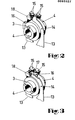
- Each contact spring 10 made of an electrically highly conductive material or galvanically provided with a coating, for example silver, consists of a base part 11, which is used for fastening. At the base part 11, the solder tail 12 adjoins at the bottom, which protrudes from the bottom of the housing half-shell and by means of which the rotary switch into one printed circuit can be soldered. On the other side of the base part there is a contact spring arm 13 which has a slight arc 14 and which is slightly bulged. At the end of the contact spring arm 13 there are two contact pieces 15 bent and spaced at right angles in the exemplary embodiment described here. As can be seen more clearly from FIGS. 2 and 3, these contact pieces 15 are inclined so that they cross each other. For this reason, more than two contact pieces were chosen in order to achieve better contact reliability and, of course, lower contact resistance. A deviating number is also conceivable.
- a switching cam 16 protruding to the side is formed on the actuating member 3 and has a detent depression 17.
- the locking lug itself is arranged between the contact pieces 15.
- the switch position ON is shown in FIG. This means that the switch cam is located approximately in the lower semicircle of the rotating range. If the switch cam is turned further, it pushes itself between the inwardly inclined contact spring arms and pushes them axially apart with respect to the actuating element, as long as the catch continues, until the catch engages in the catch recess.
- This switch position OFF is shown in Figure 3. Because the switching cam is pushed between the contact spring arms, the contact pieces are forced to open.
- a taper 19 is provided in the housing wall, which extends from the base part to the contact spring arm end.
- the rotary switch consists of five individual parts, of which two, namely the housing half-shell and the contact spring, are duplicated. This makes it possible to manufacture the rotary switch much more cost-effectively.
Landscapes
- Rotary Switch, Piano Key Switch, And Lever Switch (AREA)
- Breakers (AREA)
- Switches With Compound Operations (AREA)
- Adjustable Resistors (AREA)
- Relay Circuits (AREA)
- Mechanisms For Operating Contacts (AREA)
- Fittings On The Vehicle Exterior For Carrying Loads, And Devices For Holding Or Mounting Articles (AREA)
Priority Applications (1)
| Application Number | Priority Date | Filing Date | Title |
|---|---|---|---|
| AT83103855T ATE36620T1 (de) | 1982-05-03 | 1983-04-20 | Elektrischer drehschalter. |
Applications Claiming Priority (2)
| Application Number | Priority Date | Filing Date | Title |
|---|---|---|---|
| DE8212683U | 1982-05-03 | ||
| DE8212683U DE8212683U1 (de) | 1982-05-03 | 1982-05-03 | Elektrischer Drehschalter |
Publications (3)
| Publication Number | Publication Date |
|---|---|
| EP0093327A2 true EP0093327A2 (fr) | 1983-11-09 |
| EP0093327A3 EP0093327A3 (en) | 1986-11-26 |
| EP0093327B1 EP0093327B1 (fr) | 1988-08-17 |
Family
ID=6739687
Family Applications (1)
| Application Number | Title | Priority Date | Filing Date |
|---|---|---|---|
| EP83103855A Expired EP0093327B1 (fr) | 1982-05-03 | 1983-04-20 | Interrupteur électrique rotatif |
Country Status (5)
| Country | Link |
|---|---|
| EP (1) | EP0093327B1 (fr) |
| JP (1) | JPS58223220A (fr) |
| AT (1) | ATE36620T1 (fr) |
| DE (1) | DE8212683U1 (fr) |
| ES (1) | ES279038Y (fr) |
Cited By (5)
| Publication number | Priority date | Publication date | Assignee | Title |
|---|---|---|---|---|
| US4695691A (en) * | 1985-01-14 | 1987-09-22 | Aktieselskabet Laur.Knudsen Nordisk Elektricitets Selskab | Switch housing having fixed external nuts for attachment of contacts and terminals |
| US4697053A (en) * | 1986-03-21 | 1987-09-29 | Amp Incorporated | Rocker switch |
| EP0261448A1 (fr) * | 1986-09-06 | 1988-03-30 | Brökelmann, Jaeger & Busse GmbH & Co | Commutateur rotatif électrique |
| US4931600A (en) * | 1987-08-03 | 1990-06-05 | Dom-Sicherheitstechnik Gmbh & Co. Kg | Cylinder key switch |
| DE4430276A1 (de) * | 1994-08-26 | 1996-02-29 | Kostal Leopold Gmbh & Co Kg | Elektrischer Schalter |
Family Cites Families (1)
| Publication number | Priority date | Publication date | Assignee | Title |
|---|---|---|---|---|
| US2555801A (en) * | 1949-06-29 | 1951-06-05 | Mallory & Co Inc P R | Gasoline pump switch |
-
1982
- 1982-05-03 DE DE8212683U patent/DE8212683U1/de not_active Expired
-
1983
- 1983-04-20 AT AT83103855T patent/ATE36620T1/de not_active IP Right Cessation
- 1983-04-20 EP EP83103855A patent/EP0093327B1/fr not_active Expired
- 1983-05-02 JP JP58076324A patent/JPS58223220A/ja active Pending
- 1983-05-03 ES ES1983279038U patent/ES279038Y/es not_active Expired
Cited By (5)
| Publication number | Priority date | Publication date | Assignee | Title |
|---|---|---|---|---|
| US4695691A (en) * | 1985-01-14 | 1987-09-22 | Aktieselskabet Laur.Knudsen Nordisk Elektricitets Selskab | Switch housing having fixed external nuts for attachment of contacts and terminals |
| US4697053A (en) * | 1986-03-21 | 1987-09-29 | Amp Incorporated | Rocker switch |
| EP0261448A1 (fr) * | 1986-09-06 | 1988-03-30 | Brökelmann, Jaeger & Busse GmbH & Co | Commutateur rotatif électrique |
| US4931600A (en) * | 1987-08-03 | 1990-06-05 | Dom-Sicherheitstechnik Gmbh & Co. Kg | Cylinder key switch |
| DE4430276A1 (de) * | 1994-08-26 | 1996-02-29 | Kostal Leopold Gmbh & Co Kg | Elektrischer Schalter |
Also Published As
| Publication number | Publication date |
|---|---|
| EP0093327A3 (en) | 1986-11-26 |
| ES279038Y (es) | 1985-06-01 |
| ES279038U (es) | 1984-12-01 |
| DE8212683U1 (de) | 1982-08-19 |
| JPS58223220A (ja) | 1983-12-24 |
| EP0093327B1 (fr) | 1988-08-17 |
| ATE36620T1 (de) | 1988-09-15 |
Similar Documents
| Publication | Publication Date | Title |
|---|---|---|
| DE3922710C3 (de) | Drehschalter | |
| DE2826721C2 (fr) | ||
| DE2617186C3 (de) | Elektrischer Schalter, insbesondere in Dual-in-line-Ausführung | |
| DE2642887A1 (de) | Rotoranordnung und elektrischer schalter enthaltend eine derartige rotoranordnung | |
| DE3229280C2 (fr) | ||
| DE3425473C2 (de) | Mehrfachschalter mit drehbarem Schaltglied | |
| DE2806713C3 (de) | Elektrischer Schalter mit in Durchbrüchen angeordneten feststehenden Kontakten | |
| EP0828271B1 (fr) | Appareil électrique de vaporisation de substances actives | |
| EP0093327B1 (fr) | Interrupteur électrique rotatif | |
| EP0450366A1 (fr) | Disjoncteur commandé par bouton-poussoir | |
| DE3724736C2 (de) | Elektrischer Schalter, insbesondere für Kraftfahrzeuge | |
| EP0180008B1 (fr) | Elément fusible | |
| DE2434272A1 (de) | Elektrischer schalter | |
| DE3538939A1 (de) | Becherfoermige lagerbruecke | |
| DE3008814C2 (de) | Drehpotentiometer | |
| DE2441469C3 (de) | Elektrischer Drehschalter in geschlossener Bauweise | |
| DE2823285C2 (de) | Einstellbarer Drehwiderstand | |
| EP0726587A1 (fr) | Interrupteur rotatif ayant deux éléments de boîtier, chaque élément étant muni d'un jeu de contacts | |
| DE2016992C3 (de) | Schaltvorrichtung mit geringem Rastmoment | |
| DE2757650C3 (de) | Kontakteinrichtung für elektrischen Schalter | |
| DE2627235A1 (de) | Elektrischer schalter | |
| DE2832921C2 (de) | Elektrischer Schalter | |
| DE4328030C2 (de) | Elektrischer Drehschalter | |
| DE3737218C2 (de) | Druckfolgeschalter | |
| DE8904537U1 (de) | Zünd- und Anlaßschalter mit stirnseitigen Schleifkontakten für Kraftfahrzeuge |
Legal Events
| Date | Code | Title | Description |
|---|---|---|---|
| PUAI | Public reference made under article 153(3) epc to a published international application that has entered the european phase |
Free format text: ORIGINAL CODE: 0009012 |
|
| AK | Designated contracting states |
Designated state(s): AT BE CH FR GB IT LI NL SE |
|
| PUAL | Search report despatched |
Free format text: ORIGINAL CODE: 0009013 |
|
| AK | Designated contracting states |
Kind code of ref document: A3 Designated state(s): AT BE CH FR GB IT LI NL SE |
|
| 17P | Request for examination filed |
Effective date: 19870123 |
|
| 17Q | First examination report despatched |
Effective date: 19870819 |
|
| GRAA | (expected) grant |
Free format text: ORIGINAL CODE: 0009210 |
|
| ITF | It: translation for a ep patent filed | ||
| AK | Designated contracting states |
Kind code of ref document: B1 Designated state(s): AT BE CH FR GB IT LI NL SE |
|
| REF | Corresponds to: |
Ref document number: 36620 Country of ref document: AT Date of ref document: 19880915 Kind code of ref document: T |
|
| GBT | Gb: translation of ep patent filed (gb section 77(6)(a)/1977) | ||
| ET | Fr: translation filed | ||
| PGFP | Annual fee paid to national office [announced via postgrant information from national office to epo] |
Ref country code: GB Payment date: 19890331 Year of fee payment: 7 |
|
| PGFP | Annual fee paid to national office [announced via postgrant information from national office to epo] |
Ref country code: FR Payment date: 19890404 Year of fee payment: 7 |
|
| PGFP | Annual fee paid to national office [announced via postgrant information from national office to epo] |
Ref country code: BE Payment date: 19890410 Year of fee payment: 7 |
|
| PGFP | Annual fee paid to national office [announced via postgrant information from national office to epo] |
Ref country code: AT Payment date: 19890411 Year of fee payment: 7 |
|
| PGFP | Annual fee paid to national office [announced via postgrant information from national office to epo] |
Ref country code: SE Payment date: 19890414 Year of fee payment: 7 |
|
| ITTA | It: last paid annual fee | ||
| PGFP | Annual fee paid to national office [announced via postgrant information from national office to epo] |
Ref country code: NL Payment date: 19890430 Year of fee payment: 7 |
|
| PGFP | Annual fee paid to national office [announced via postgrant information from national office to epo] |
Ref country code: CH Payment date: 19890523 Year of fee payment: 7 |
|
| PLBE | No opposition filed within time limit |
Free format text: ORIGINAL CODE: 0009261 |
|
| STAA | Information on the status of an ep patent application or granted ep patent |
Free format text: STATUS: NO OPPOSITION FILED WITHIN TIME LIMIT |
|
| 26N | No opposition filed | ||
| PG25 | Lapsed in a contracting state [announced via postgrant information from national office to epo] |
Ref country code: GB Effective date: 19900420 Ref country code: AT Effective date: 19900420 |
|
| PG25 | Lapsed in a contracting state [announced via postgrant information from national office to epo] |
Ref country code: SE Effective date: 19900421 |
|
| PG25 | Lapsed in a contracting state [announced via postgrant information from national office to epo] |
Ref country code: LI Effective date: 19900430 Ref country code: CH Effective date: 19900430 Ref country code: BE Effective date: 19900430 |
|
| BERE | Be: lapsed |
Owner name: PREH ELEKTROFEINMECHANISCHE WERKE JAKOB PREH NACH Effective date: 19900430 |
|
| PG25 | Lapsed in a contracting state [announced via postgrant information from national office to epo] |
Ref country code: NL Effective date: 19901101 |
|
| NLV4 | Nl: lapsed or anulled due to non-payment of the annual fee | ||
| GBPC | Gb: european patent ceased through non-payment of renewal fee | ||
| PG25 | Lapsed in a contracting state [announced via postgrant information from national office to epo] |
Ref country code: FR Effective date: 19901228 |
|
| REG | Reference to a national code |
Ref country code: CH Ref legal event code: PL |
|
| REG | Reference to a national code |
Ref country code: FR Ref legal event code: ST |
|
| EUG | Se: european patent has lapsed |
Ref document number: 83103855.9 Effective date: 19910115 |