EP0093345A2 - Pompe à chaleur - Google Patents
Pompe à chaleur Download PDFInfo
- Publication number
- EP0093345A2 EP0093345A2 EP83103938A EP83103938A EP0093345A2 EP 0093345 A2 EP0093345 A2 EP 0093345A2 EP 83103938 A EP83103938 A EP 83103938A EP 83103938 A EP83103938 A EP 83103938A EP 0093345 A2 EP0093345 A2 EP 0093345A2
- Authority
- EP
- European Patent Office
- Prior art keywords
- heat pump
- pulse
- pump according
- increasing
- controlled
- Prior art date
- Legal status (The legal status is an assumption and is not a legal conclusion. Google has not performed a legal analysis and makes no representation as to the accuracy of the status listed.)
- Withdrawn
Links
- 239000002904 solvent Substances 0.000 claims abstract description 7
- 238000011144 upstream manufacturing Methods 0.000 claims abstract 2
- 239000003507 refrigerant Substances 0.000 claims description 25
- 238000010521 absorption reaction Methods 0.000 claims description 10
- 238000007906 compression Methods 0.000 claims description 10
- 230000006835 compression Effects 0.000 claims description 9
- 238000001179 sorption measurement Methods 0.000 claims 2
- 239000002826 coolant Substances 0.000 abstract 1
- 239000000243 solution Substances 0.000 description 19
- 239000006096 absorbing agent Substances 0.000 description 9
- QGZKDVFQNNGYKY-UHFFFAOYSA-N Ammonia Chemical compound N QGZKDVFQNNGYKY-UHFFFAOYSA-N 0.000 description 4
- 238000010586 diagram Methods 0.000 description 4
- 239000007788 liquid Substances 0.000 description 3
- 238000000034 method Methods 0.000 description 3
- 229910021529 ammonia Inorganic materials 0.000 description 2
- 230000007613 environmental effect Effects 0.000 description 2
- 230000002349 favourable effect Effects 0.000 description 2
- 238000002347 injection Methods 0.000 description 2
- 239000007924 injection Substances 0.000 description 2
- 239000003990 capacitor Substances 0.000 description 1
- 238000011109 contamination Methods 0.000 description 1
- 238000001816 cooling Methods 0.000 description 1
- 230000007423 decrease Effects 0.000 description 1
- 238000011161 development Methods 0.000 description 1
- 230000018109 developmental process Effects 0.000 description 1
- 230000000694 effects Effects 0.000 description 1
- 239000012530 fluid Substances 0.000 description 1
- 239000000446 fuel Substances 0.000 description 1
- 238000010438 heat treatment Methods 0.000 description 1
- 230000007774 longterm Effects 0.000 description 1
- 238000004519 manufacturing process Methods 0.000 description 1
- 238000012544 monitoring process Methods 0.000 description 1
- 238000005057 refrigeration Methods 0.000 description 1
- 230000007704 transition Effects 0.000 description 1
Images


Classifications
-
- F—MECHANICAL ENGINEERING; LIGHTING; HEATING; WEAPONS; BLASTING
- F25—REFRIGERATION OR COOLING; COMBINED HEATING AND REFRIGERATION SYSTEMS; HEAT PUMP SYSTEMS; MANUFACTURE OR STORAGE OF ICE; LIQUEFACTION SOLIDIFICATION OF GASES
- F25B—REFRIGERATION MACHINES, PLANTS OR SYSTEMS; COMBINED HEATING AND REFRIGERATION SYSTEMS; HEAT PUMP SYSTEMS
- F25B49/00—Arrangement or mounting of control or safety devices
-
- F—MECHANICAL ENGINEERING; LIGHTING; HEATING; WEAPONS; BLASTING
- F25—REFRIGERATION OR COOLING; COMBINED HEATING AND REFRIGERATION SYSTEMS; HEAT PUMP SYSTEMS; MANUFACTURE OR STORAGE OF ICE; LIQUEFACTION SOLIDIFICATION OF GASES
- F25B—REFRIGERATION MACHINES, PLANTS OR SYSTEMS; COMBINED HEATING AND REFRIGERATION SYSTEMS; HEAT PUMP SYSTEMS
- F25B30/00—Heat pumps
- F25B30/02—Heat pumps of the compression type
-
- F—MECHANICAL ENGINEERING; LIGHTING; HEATING; WEAPONS; BLASTING
- F25—REFRIGERATION OR COOLING; COMBINED HEATING AND REFRIGERATION SYSTEMS; HEAT PUMP SYSTEMS; MANUFACTURE OR STORAGE OF ICE; LIQUEFACTION SOLIDIFICATION OF GASES
- F25B—REFRIGERATION MACHINES, PLANTS OR SYSTEMS; COMBINED HEATING AND REFRIGERATION SYSTEMS; HEAT PUMP SYSTEMS
- F25B30/00—Heat pumps
- F25B30/04—Heat pumps of the sorption type
-
- F—MECHANICAL ENGINEERING; LIGHTING; HEATING; WEAPONS; BLASTING
- F25—REFRIGERATION OR COOLING; COMBINED HEATING AND REFRIGERATION SYSTEMS; HEAT PUMP SYSTEMS; MANUFACTURE OR STORAGE OF ICE; LIQUEFACTION SOLIDIFICATION OF GASES
- F25B—REFRIGERATION MACHINES, PLANTS OR SYSTEMS; COMBINED HEATING AND REFRIGERATION SYSTEMS; HEAT PUMP SYSTEMS
- F25B41/00—Fluid-circulation arrangements
- F25B41/30—Expansion means; Dispositions thereof
- F25B41/31—Expansion valves
- F25B41/34—Expansion valves with the valve member being actuated by electric means, e.g. by piezoelectric actuators
- F25B41/345—Expansion valves with the valve member being actuated by electric means, e.g. by piezoelectric actuators by solenoids
- F25B41/347—Expansion valves with the valve member being actuated by electric means, e.g. by piezoelectric actuators by solenoids with the valve member being opened and closed cyclically, e.g. with pulse width modulation
-
- F—MECHANICAL ENGINEERING; LIGHTING; HEATING; WEAPONS; BLASTING
- F25—REFRIGERATION OR COOLING; COMBINED HEATING AND REFRIGERATION SYSTEMS; HEAT PUMP SYSTEMS; MANUFACTURE OR STORAGE OF ICE; LIQUEFACTION SOLIDIFICATION OF GASES
- F25B—REFRIGERATION MACHINES, PLANTS OR SYSTEMS; COMBINED HEATING AND REFRIGERATION SYSTEMS; HEAT PUMP SYSTEMS
- F25B41/00—Fluid-circulation arrangements
- F25B41/30—Expansion means; Dispositions thereof
- F25B41/385—Dispositions with two or more expansion means arranged in parallel on a refrigerant line leading to the same evaporator
-
- Y—GENERAL TAGGING OF NEW TECHNOLOGICAL DEVELOPMENTS; GENERAL TAGGING OF CROSS-SECTIONAL TECHNOLOGIES SPANNING OVER SEVERAL SECTIONS OF THE IPC; TECHNICAL SUBJECTS COVERED BY FORMER USPC CROSS-REFERENCE ART COLLECTIONS [XRACs] AND DIGESTS
- Y02—TECHNOLOGIES OR APPLICATIONS FOR MITIGATION OR ADAPTATION AGAINST CLIMATE CHANGE
- Y02B—CLIMATE CHANGE MITIGATION TECHNOLOGIES RELATED TO BUILDINGS, e.g. HOUSING, HOUSE APPLIANCES OR RELATED END-USER APPLICATIONS
- Y02B30/00—Energy efficient heating, ventilation or air conditioning [HVAC]
- Y02B30/70—Efficient control or regulation technologies, e.g. for control of refrigerant flow, motor or heating
Definitions
- the present invention relates to a heat pump according to the preamble of the main claim.
- Such heat pumps be they compression, absorption or absorption heat pumps, form a circuit for at least one refrigerant, possibly also for a solvent, this circuit being divided into a high-pressure (high-temperature) and a low-pressure (low-temperature) part can.
- High and low pressure parts are connected to one another via the expansion valve in the direction of the low pressure part or via the compressor or generator or cooker in the direction of the high pressure part.
- the present invention is therefore based on the object of finding a solution to the problem of maintaining the small cross sections in the course of the refrigerant vapor or solvent path.
- a collecting space is provided, which is only put into the evaporator after sufficient filling by opening the shut-off valve connected downstream of it.
- an absorption heat pump there are analogue collection rooms between condenser and evaporator in the course of the refrigerant vapor path, on the other hand between expeller and absorber
- the collecting space is initially filled with refrigerant vapor or solvent, which is then added in batches to the downstream parts of the circuit.
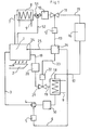
- 1 is a cooker that is heated by a burner 2.
- the cooker is supplied with a rich solution via a return line 3, which is provided with a circulation pump 4, the drive motor 5 of which is supplied with electrical energy via a control line 6.
- a line 7 for refrigerant vapor leads from the cooker to a condenser 8, which forms a heat exchanger for feeding a consumer 9.
- a collecting space 10 is arranged on the output side of the capacitor 8.
- the valve has only two possible positions.
- a valve 11 is assigned to the outlet of the collecting space and is controlled by an actuator 12, the actuating line 13 of which leads to a control element 14, from which line 6 also branches.
- a line 15 for liquid refrigerant leads from the collecting space 10 to an evaporator 16, from which a refrigerant vapor line 17 leads to an absorber 18 through which a consumer heat exchanger tube coil passes. Output side of the The absorber 18 is connected to the line 3, a collecting space 50 for rich solution being predefined between the pump 4 and the absorber 18.
- a line 19 for poor solution extends from the cooker 1, which line is connected via a collecting space 20, in the output of which a valve 21 is arranged, the actuator 22 of which is connected to a control line 23 which originates from the control device 14.
- the absorption heat pump just described has the following function: The fuel that is fed to the burner and is burned heats the stove.
- the rich solution supplied via line 3 separates into refrigerant vapor, which via line 7, and into poor solution, which is removed via line 19 from the interior of the cooker.
- the refrigerant vapor is cooled and condensed in the condenser 8 under the influence of the consumer fluid present there.
- the liquefied refrigerant vapor flows into the collecting space 10 until a certain amount has been collected there. The same happens with the poor solution, which enters the collecting space 20 via the line 19.
- the actuators 12 and 22 so that the valves 11 and 21 open.
- the maximum throughput of ammonia per hour at the design point of the heat pump that is at approximately minus 5 ° C, is 12.5 kg per hour.
- the throughput In order to achieve this throughput in an achievable timing ratio of, for example, fifteen seconds, the throughput must be value to be divided by 240. That makes about 50 g, this requires a space of 70 cm 3 . Since this value represents an average value, a minimum including the volume of the collecting space of 50 cm 3 and a maximum of the collecting space of 100 cm 3 must be assumed.
- the plenum 20 can be sized by assuming the hourly throughput of poor solution through the system, which is 50 kg per hour. If this throughput is divided by the same timing ratio, i.e. by 240, a mass of 200 g results, which corresponds to a volume space of 280 cm 3 . This volume value also represents an average, the bandwidth of the volume ranges from a minimum of 200 cm 3 to a maximum of 400 cm 3 . It can now be said that the ratio of the collecting spaces 10 and 20 can be described by assuming that the volume of the collecting space 10 relates to the volume of the collecting space 20, like the hourly throughput of ammonia to the hourly throughput of poor solution. The division of the number determined previously gives a ratio of 0.2 to 0.25.
- the pulse-pause ratio of the actuation or closing, that is to say collection, of the valves 11 and 19 can be controlled linearly proportionally in accordance with a curve 30 as a function of the output of the heat pump: in the abscissa there is a pulse pause ratio P represented to P from zero to one.
- a ratio of zero means that the opening time is zero during the entire pulse, that is to say the collection time corresponds to the entire period. With a pulse pause ratio of one, this means that the opening time dominates the total duration of the period.
- a pulse-pause ratio of fifty percent accordingly means that the switch-on and switch-off times, that is to say collection and injection, are in each case the same within a period.
- the ordinate shows the power from zero to one hundred percent of the respective heat pump, the reference variable being the power delivered to the consumer 9.
- the pulse pause ratio is equally zero.
- a maximum pulse-pause ratio of twenty to twenty-five percent is achieved with a hundred percent output from the heat pump, that is to say that when the currents are collected, for example ten seconds, the throttle valves open two to 2.5 in order to inject into the evaporator and absorber. All intermediate points correspond to a linear proportional interpolation between these two extreme values 31 and 32.
- the burner and the solvent pump run continuously regardless of the duty cycle of filling and emptying the collecting spaces.
- the circuit according to the invention is also suitable for compression heat pumps.
- a compressor 41 is driven by an electric motor 43 via a shaft 42 and conveys compressed refrigerant vapor into a line 44, which leads to the condenser 8, which feeds a consumer 9.
- the collecting chamber 10 is arranged in the course of the line 15 for refrigerant vapor, the outlet of the latter from the valve 11 is controlled, which is controlled by the actuator 12 via the line 13.
- the line 15 leads to the evaporator 16, which is connected to the compressor 41 via a return line 45.
- the control device 14 is connected via the measuring line 25 to a temperature or pressure sensor 24, the control line 13 is connected to the control device 14.
- the function of the compression heat pump according to FIG. Two is as follows:
- the electric motor 43 drives the compressor 41 via the shaft 42, which takes vaporous refrigerant from the line 45 under low pressure conditions and presses it into the line 44, compressing it.
- the refrigerant condenses in the condenser 8 under the influence of the cooling effect of the consumer 9, which is heated up.
- the condensed refrigerant is passed on the outlet side of the condenser via line 15 into the collecting space 10, which it can leave in accordance with the control commands of the actuator 12, which is controlled by the control device 14.
- the refrigerant is thus fed in batches via line 15 into the evaporator 16, where it evaporates while absorbing heat from the environment and returns to the compressor in line 45.
- a controllable compressor In contrast to conventional, non-controllable compressors in standard electric compression heat pumps, a controllable compressor, but at least a two-stage compressor, is required to implement this circuit or control method.
- a two-stage compressor is a compressor that, in addition to its nominal speed and nominal power consumption, also has one for example by a third to a fifth lower speed with correspondingly lower power consumption.
- the collection phase pause
- the injection phase pulse
- the electro-compression heat pump can be adapted very well to the heating system.
- the electric compression heat pump no longer works in on / off mode, but oscillates between base load and full load depending on the pulse pause ratio.
- a ramp-like, smooth transition from full load to partial load also has a favorable effect on the service life of the compressor. Thermodynamically, higher annual efficiencies can also be achieved due to both lower plant downtime losses and the fact that the entire refrigeration cycle is not continuously operated (in / out) in fully stationary operation.
- the performance of the heat pump is determined by the temperature or pressure sensor 24.
- the signals on line 25 are thus a measure of the power to be supplied to consumer 9.
- the pulse pause ratio of the opening and closing times of the valve 11 and the valves 11 and 19 is controlled by control commands on the lines 13 and 23, respectively. With high power output, there is a pulse-pause ratio in the vicinity of twenty to twenty-five percent, with very low power output, a pulse-pause ratio of three to five percent.
Landscapes
- Engineering & Computer Science (AREA)
- Physics & Mathematics (AREA)
- Mechanical Engineering (AREA)
- Thermal Sciences (AREA)
- General Engineering & Computer Science (AREA)
- Sorption Type Refrigeration Machines (AREA)
- Compression-Type Refrigeration Machines With Reversible Cycles (AREA)
Applications Claiming Priority (4)
| Application Number | Priority Date | Filing Date | Title |
|---|---|---|---|
| DE8213014 | 1982-05-03 | ||
| DE8213014U | 1982-05-03 | ||
| DE3216874 | 1982-05-03 | ||
| DE19833314713 DE3314713A1 (de) | 1982-05-03 | 1983-04-22 | Waermepumpe |
Publications (2)
| Publication Number | Publication Date |
|---|---|
| EP0093345A2 true EP0093345A2 (fr) | 1983-11-09 |
| EP0093345A3 EP0093345A3 (fr) | 1984-07-25 |
Family
ID=27190078
Family Applications (1)
| Application Number | Title | Priority Date | Filing Date |
|---|---|---|---|
| EP83103938A Withdrawn EP0093345A3 (fr) | 1982-05-03 | 1983-04-22 | Pompe à chaleur |
Country Status (2)
| Country | Link |
|---|---|
| EP (1) | EP0093345A3 (fr) |
| DE (1) | DE3314713A1 (fr) |
Cited By (3)
| Publication number | Priority date | Publication date | Assignee | Title |
|---|---|---|---|---|
| EP1148305A1 (fr) * | 2000-04-17 | 2001-10-24 | Vaillant GmbH | Pompe à chaleur à adsorption |
| CN105423621A (zh) * | 2016-01-11 | 2016-03-23 | 东北电力大学 | 一种双热源喷气增焓热泵系统 |
| CN118517672A (zh) * | 2024-07-24 | 2024-08-20 | 浙江镕达永能压缩机有限公司 | 一种组合式蒸汽发生系统及运行方法 |
Families Citing this family (2)
| Publication number | Priority date | Publication date | Assignee | Title |
|---|---|---|---|---|
| DE3410764A1 (de) * | 1983-03-22 | 1984-09-27 | Joh. Vaillant Gmbh U. Co, 5630 Remscheid | Verfahren zum steuern einer elektrischen ausgangsgroesse mittels eines pulspausenverhaeltnisses |
| RU2731684C1 (ru) * | 2019-11-19 | 2020-09-07 | Федеральное государственное бюджетное образовательное учреждение высшего образования "Казанский государственный энергетический университет" (ФГБОУ ВО "КГЭУ") | Тригенерационная установка |
Family Cites Families (9)
| Publication number | Priority date | Publication date | Assignee | Title |
|---|---|---|---|---|
| DE1109191B (de) * | 1957-12-12 | 1961-06-22 | Siemens Ag | Verdichter-Motor-Aggregat fuer Kaeltemaschinen |
| CH496931A (de) * | 1968-09-26 | 1970-09-30 | Luwa Ag | Regelbare Kompressor-Kälteanlage |
| DE1914105A1 (de) * | 1969-03-20 | 1971-03-04 | F P L Eberhart Gmbh & Co Kg | Temperaturregeleinrichtung |
| FR2222616A1 (en) * | 1973-03-19 | 1974-10-18 | Bruch Guy | Modulated refrigeration energy supply system - uses sets of impulses to control adjustments temp. regulation |
| AU515910B2 (en) * | 1978-10-19 | 1981-05-07 | Matsushita Electric Industrial Co., Ltd. | Air conditioning system having a plurality of indoor units |
| DE2900388A1 (de) * | 1979-01-04 | 1980-07-10 | Borsig Gmbh | Absorptionskaeltemaschine mit speichereinrichtung fuer den betrieb mit zeitlich unterschiedlichem anfall von heizenergie und kaeltebedarf |
| US4270361A (en) * | 1979-03-14 | 1981-06-02 | Barge Michael A | Energy management controller for centrifugal water chiller |
| JPS6012532B2 (ja) * | 1980-10-13 | 1985-04-02 | 株式会社東芝 | 空気調和装置の制御方法 |
| DE3129410A1 (de) * | 1981-07-25 | 1983-02-17 | Erich Ing. Pöhlmann (grad.), 8650 Kulmbach | Expansionsventilanordnung in waermepumpen |
-
1983
- 1983-04-22 EP EP83103938A patent/EP0093345A3/fr not_active Withdrawn
- 1983-04-22 DE DE19833314713 patent/DE3314713A1/de not_active Withdrawn
Cited By (3)
| Publication number | Priority date | Publication date | Assignee | Title |
|---|---|---|---|---|
| EP1148305A1 (fr) * | 2000-04-17 | 2001-10-24 | Vaillant GmbH | Pompe à chaleur à adsorption |
| CN105423621A (zh) * | 2016-01-11 | 2016-03-23 | 东北电力大学 | 一种双热源喷气增焓热泵系统 |
| CN118517672A (zh) * | 2024-07-24 | 2024-08-20 | 浙江镕达永能压缩机有限公司 | 一种组合式蒸汽发生系统及运行方法 |
Also Published As
| Publication number | Publication date |
|---|---|
| DE3314713A1 (de) | 1983-11-03 |
| EP0093345A3 (fr) | 1984-07-25 |
Similar Documents
| Publication | Publication Date | Title |
|---|---|---|
| DE4439780A1 (de) | Kompressor-Kältemaschine | |
| DE3716393A1 (de) | Kaelteanlage | |
| DE3215141A1 (de) | Klimaanlage | |
| DE102012111455A1 (de) | Kältemittelkreislauf einer Fahrzeugklimaanlage sowie Verfahren zur Klimatisierung eines Fahrzeuginnenraums | |
| DE3530242C2 (fr) | ||
| EP0195279A2 (fr) | Procédé pour la régulation d'installations frigorifiques ou pompes à chaleur à absorption | |
| DE2856767A1 (de) | Absorptions-waermepumpe veraenderbarer ausgangs-waermeleistung | |
| WO2000014458A2 (fr) | Machine frigorifique a absorption | |
| DE2728273A1 (de) | Verbrennungsmotorisch betriebene waermepumpenanordnung | |
| DE3314713A1 (de) | Waermepumpe | |
| DE10108768C2 (de) | Absorptionskälteanlage mit Niedertemperaturnutzung | |
| EP0152608A2 (fr) | Procédé de commande d'une installation frigorifique complexe | |
| DE19832682C2 (de) | Abtaueinrichtung für einen Verdampfer einer Wärmepumpe oder eines Klimageräts | |
| DE3018706A1 (de) | Waermepumpe | |
| EP0038990B1 (fr) | Méthode pour la régulation d'une installation de chauffage comprenant une pompe à chaleur à absorption | |
| DE2702489C2 (de) | Verfahren und Vorrichtung zum automatischen Optimieren des Betriebspunktes einer Wärmepumpe | |
| EP1957894A1 (fr) | Procede d'utilisation d'un refrigerateur et refrigerateur dote d'un raccordement avec retard du compresseur | |
| EP2810003B1 (fr) | Appareil réfrigérant à deux compartiments de stockage | |
| DE10338388B3 (de) | Verfahren zur Regelung einer Klimaanlage | |
| DE102019123114B3 (de) | Vorrichtung und Verfahren zum Regeln des Durchflusses eines Kältemittels in einem Kältemittelkreislauf | |
| DE2150162C3 (de) | Anordnung zum automatischen Abtauen eines Verdampferteils in einem Absorp tionskalteapparat | |
| DE2309337C3 (de) | Anfahrregelung für Kaltdampfkältemaschinen | |
| DE3023769A1 (de) | Verfahren zum umschalten einer waermepumpe | |
| DE19730699A1 (de) | Verfahren zum Betreiben einer diskontinuierlichen Adsorptionswärmepumpe und Adsorptionswärmepumpe zur Durchführung des Verfahrens | |
| DE3129410A1 (de) | Expansionsventilanordnung in waermepumpen |
Legal Events
| Date | Code | Title | Description |
|---|---|---|---|
| PUAI | Public reference made under article 153(3) epc to a published international application that has entered the european phase |
Free format text: ORIGINAL CODE: 0009012 |
|
| AK | Designated contracting states |
Designated state(s): AT BE CH DE FR GB IT LI LU NL SE |
|
| PUAL | Search report despatched |
Free format text: ORIGINAL CODE: 0009013 |
|
| AK | Designated contracting states |
Designated state(s): AT BE CH DE FR GB IT LI LU NL SE |
|
| STAA | Information on the status of an ep patent application or granted ep patent |
Free format text: STATUS: THE APPLICATION IS DEEMED TO BE WITHDRAWN |
|
| 18D | Application deemed to be withdrawn |
Effective date: 19850326 |
|
| RIN1 | Information on inventor provided before grant (corrected) |
Inventor name: KANTNER, ALEXANDER, DR. |