EP0093347A2 - Dispositif pour travaux de couverture - Google Patents
Dispositif pour travaux de couverture Download PDFInfo
- Publication number
- EP0093347A2 EP0093347A2 EP83103947A EP83103947A EP0093347A2 EP 0093347 A2 EP0093347 A2 EP 0093347A2 EP 83103947 A EP83103947 A EP 83103947A EP 83103947 A EP83103947 A EP 83103947A EP 0093347 A2 EP0093347 A2 EP 0093347A2
- Authority
- EP
- European Patent Office
- Prior art keywords
- frame
- seat
- rollers
- arms
- support surfaces
- Prior art date
- Legal status (The legal status is an assumption and is not a legal conclusion. Google has not performed a legal analysis and makes no representation as to the accuracy of the status listed.)
- Withdrawn
Links
Images

Classifications
-
- E—FIXED CONSTRUCTIONS
- E04—BUILDING
- E04D—ROOF COVERINGS; SKY-LIGHTS; GUTTERS; ROOF-WORKING TOOLS
- E04D15/00—Apparatus or tools for roof working
- E04D15/02—Apparatus or tools for roof working for roof coverings comprising tiles, shingles, or like roofing elements
Definitions
- the invention relates to a device for roof work, which in particular should facilitate the work in connection with the application of the ridge pans.
- a device for roof work which in particular should facilitate the work in connection with the application of the ridge pans.
- the work must be carried out partly while sitting and partly kneeling, with both roof areas serving as standing or sitting areas.
- carrying the aids or tools, such as mortar buckets etc. has proven to be difficult and cumbersome.
- the invention proposes a device which is characterized by a frame which carries a seat, with receptacle fastening or suspension devices for tools or aids on the seat or frame, and also supporting elements for the frame or the seat angled support surfaces.
- a frame with the seat is placed in the area of the ridge, the support surfaces being supported in each case on the roof plates of the two roof surfaces.
- the frame forms a seat that makes work much easier. Tools and other aids can simply be attached to the frame or seat and the frame is pushed further as work progresses, preferably backwards, which is easy to carry out due to the support surfaces provided.
- the support surfaces can be designed, for example, as sliding surfaces or as rollers.
- the arrangement of caterpillar-like elements is also possible.
- the support surface on the roof surfaces or the top row of roof tiles is significantly improved, if the support surfaces or rollers are mounted on supports which can be pivoted about axes parallel to one another. As a result, for example, the rollers can each be aligned with the roof surface, it being advisable to use wide rollers or to arrange rollers on both sides of the carrier.
- arms which are directed obliquely outwards and downwards are attached to the seat or frame, at the ends of which auxiliary arms are directed essentially at right angles and whose lower ends support the support surfaces. This design creates enough space for the ridge pans to be applied.
- the effective length of the auxiliary arm is adjustable, which can be done, for example, by a pipe guide for the auxiliary arms at the arm ends. This ensures that the distance between the seat and the ridge pan is as small as possible, but that there is always enough space to carry out the work without any disabilities.
- the rafters of the roof structure are designated by 12, the roof battens fastened thereon by 13 and the roof tiles or roof tiles supported by the roof battens by 14.
- the ridge tile 15 shown with dash-dotted lines is to be fastened over the uppermost roof panels on both roof sides.
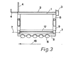
- the device that facilitates this work consists essentially of the frame 1 on which the seat 2 is arranged.
- the frame 1 or the seat 2 carry at one end, in particular at the front end, receiving devices 3 which are designed like containers. Small parts, for example nails, can be inserted into these holding devices.
- the various tools or auxiliary devices can be hung on the suspension devices 4, which are designed like hooks or, as at 4 'project upwards.
- the frame 1 or the seat 2 is supported by the arms 8, which have 8 pipe guides 10 at their ends.
- This Rohrriosun g s take the auxiliary arms on the 9th Pins can be inserted into the bores 16 in order to determine the desired position of the auxiliary arms 9 relative to the arms 8.
- auxiliary arms 9 are arranged at the four corners of the frame 1.
- the auxiliary arms 9 on both sides are connected by rods 17.
- the supports 5, which accommodate the axes of the rollers 6, are connected to the rods 17 via the joints with the axes 7.
- the rollers 5 are provided on both sides of the carrier 5.
- rollers 6 It is advisable to provide a larger number of rollers 6 in order to be able to use the device even if the roof panels 14 have corrugations, so that a secure displacement along the ridge of the roof is possible. It is advantageous if the rollers 6 are arranged offset on both sides of the carrier 5 by half a center distance. The use of a caterpillar track, which is guided by the rollers 6, is also possible.
- Locking devices can be provided for the axes 7, but this is not necessary.
- the training can also be such that the carrier 5 aligns itself automatically in order to provide a good support for the rollers 6.
- the device can be moved well over the ridge pans 15. With a steeper roof, the effective length of the auxiliary arms 9 will have to be increased accordingly.
- the operator sits on the seat 2, the legs being on both sides of the ridge.
- the container-like receiving device is generally located in front of the operator and the device is normally moved in the direction of arrow 18.
Landscapes
- Engineering & Computer Science (AREA)
- Architecture (AREA)
- Civil Engineering (AREA)
- Structural Engineering (AREA)
- Tents Or Canopies (AREA)
- Agricultural Machines (AREA)
- Body Structure For Vehicles (AREA)
Applications Claiming Priority (2)
| Application Number | Priority Date | Filing Date | Title |
|---|---|---|---|
| DE8212391U | 1982-04-29 | ||
| DE19828212391 DE8212391U1 (de) | 1982-04-29 | 1982-04-29 | Vorrichtung fuer dacharbeiten |
Publications (2)
| Publication Number | Publication Date |
|---|---|
| EP0093347A2 true EP0093347A2 (fr) | 1983-11-09 |
| EP0093347A3 EP0093347A3 (fr) | 1985-03-06 |
Family
ID=6739589
Family Applications (1)
| Application Number | Title | Priority Date | Filing Date |
|---|---|---|---|
| EP83103947A Withdrawn EP0093347A3 (fr) | 1982-04-29 | 1983-04-22 | Dispositif pour travaux de couverture |
Country Status (2)
| Country | Link |
|---|---|
| EP (1) | EP0093347A3 (fr) |
| DE (1) | DE8212391U1 (fr) |
Cited By (2)
| Publication number | Priority date | Publication date | Assignee | Title |
|---|---|---|---|---|
| GB2229482A (en) * | 1989-03-17 | 1990-09-26 | Reilly Patrick Joseph O | Roof seat |
| CN112482674A (zh) * | 2020-11-27 | 2021-03-12 | 童温霞 | 一种基于新型环保材料的建筑瓦片搭设机及其使用方法 |
Family Cites Families (4)
| Publication number | Priority date | Publication date | Assignee | Title |
|---|---|---|---|---|
| US2327317A (en) * | 1941-10-09 | 1943-08-17 | Fred D Randall | Attachment for ladders |
| US2635926A (en) * | 1949-11-19 | 1953-04-21 | United States Steel Corp | Welder's chair |
| US3058542A (en) * | 1961-06-23 | 1962-10-16 | Gerald J Rogalla | Roof platforms and carriers |
| NL7315944A (en) * | 1973-11-21 | 1975-05-23 | Nederhoed Staal En Machinebouw | Roof tile laying system - uses transverse slats as guide rails for truck carrying tile stock |
-
1982
- 1982-04-29 DE DE19828212391 patent/DE8212391U1/de not_active Expired
-
1983
- 1983-04-22 EP EP83103947A patent/EP0093347A3/fr not_active Withdrawn
Cited By (3)
| Publication number | Priority date | Publication date | Assignee | Title |
|---|---|---|---|---|
| GB2229482A (en) * | 1989-03-17 | 1990-09-26 | Reilly Patrick Joseph O | Roof seat |
| CN112482674A (zh) * | 2020-11-27 | 2021-03-12 | 童温霞 | 一种基于新型环保材料的建筑瓦片搭设机及其使用方法 |
| CN112482674B (zh) * | 2020-11-27 | 2021-12-10 | 徐州务欣信息科技有限公司 | 一种基于新型环保材料的建筑瓦片搭设机及其使用方法 |
Also Published As
| Publication number | Publication date |
|---|---|
| DE8212391U1 (de) | 1982-08-26 |
| EP0093347A3 (fr) | 1985-03-06 |
Similar Documents
| Publication | Publication Date | Title |
|---|---|---|
| DE10300102B4 (de) | Gestell zum Unterbringen von Platten | |
| DE3520084C2 (de) | Rohrhandhabungssystem | |
| DE2842123C2 (de) | Firstabdichtung | |
| AT394077B (de) | Einrichtung an einer schalung zur errichtung eines mauerwerkes | |
| DE2921636C2 (de) | Gerät mit Hubvorrichtung zum Klettern an einer Wand | |
| EP0093347A2 (fr) | Dispositif pour travaux de couverture | |
| DE2833439C2 (de) | Vorrichtung zum bleibenden Verschalen von Flächen, insbesondere von Wänden oder Innendachflächen von Gebäuden, mit Platten | |
| DE2151515C3 (de) | Vorrichtung zum Anschließen eines beweglichen Behälters an eine Umfüllstation | |
| EP0157292B1 (fr) | Dispositif pour transporter des matériaux sur des toits inclinés | |
| DE3709441A1 (de) | Auf dem dach eines gedeckten gebaeudes abstuetzbares kamingeruest | |
| DE2700284A1 (de) | Vorrichtung zur befoerderung von insbesondere kleinen gegenstaenden in allen richtungen | |
| DE1759525A1 (de) | Hebevorrichtung fuer Gleitschalungen bei der Herstellung von Betonbauteilen mit mindestens einer schraegen Wandflaeche | |
| DE3520449C1 (de) | Schrägbauaufzug | |
| DE2829863C2 (de) | Vorrichtung zum Herstellen von senkrecht stehenden Wandtafeln aus Mauersteinen | |
| DE69119167T3 (de) | Verfahren für die Installierung von die Schachttüren eines Aufzugs | |
| DE3641985A1 (de) | Verfahren zum verlegen oder austauschen von platten an fassaden | |
| DE60013390T2 (de) | Apparatus for cutting workpieces such as tiles | |
| DE2261036C3 (de) | Anordnung an Arbeitstischen zur Aufstellung von Geräten | |
| DE3632735A1 (de) | Vorrichtung zur erleichterung des zufuehrens von dachdeckungselementen, wie dachziegel oder dergleichen, vom lagerplatz zum verlegebereich auf einem dach | |
| DE8632805U1 (de) | Hebevorrichtung für Platten | |
| DE3400667C2 (fr) | ||
| DE2618657A1 (de) | Moertelbandauflegevorrichtung zur herstellung von moertelbettungen an waenden | |
| DE3441398C2 (de) | Vorrichtung zum Befestigen einer Leiter oder dergleichen auf einem Dach | |
| DE8524796U1 (de) | Vorrichtung zum Greifen und Versetzen von Deckenziegeln | |
| DE10139419C1 (de) | Befestigungsklammer |
Legal Events
| Date | Code | Title | Description |
|---|---|---|---|
| PUAI | Public reference made under article 153(3) epc to a published international application that has entered the european phase |
Free format text: ORIGINAL CODE: 0009012 |
|
| AK | Designated contracting states |
Designated state(s): AT CH DE FR GB LI |
|
| PUAL | Search report despatched |
Free format text: ORIGINAL CODE: 0009013 |
|
| AK | Designated contracting states |
Designated state(s): AT CH DE FR GB LI |
|
| RAP1 | Party data changed (applicant data changed or rights of an application transferred) |
Owner name: ZEH, WOLFGANG |
|
| STAA | Information on the status of an ep patent application or granted ep patent |
Free format text: STATUS: THE APPLICATION IS DEEMED TO BE WITHDRAWN |
|
| 18D | Application deemed to be withdrawn |
Effective date: 19851031 |