EP0093359A1 - Tiroir cylindrique à voies multiples - Google Patents
Tiroir cylindrique à voies multiples Download PDFInfo
- Publication number
- EP0093359A1 EP0093359A1 EP83104002A EP83104002A EP0093359A1 EP 0093359 A1 EP0093359 A1 EP 0093359A1 EP 83104002 A EP83104002 A EP 83104002A EP 83104002 A EP83104002 A EP 83104002A EP 0093359 A1 EP0093359 A1 EP 0093359A1
- Authority
- EP
- European Patent Office
- Prior art keywords
- control
- housing
- face
- channel
- groove
- Prior art date
- Legal status (The legal status is an assumption and is not a legal conclusion. Google has not performed a legal analysis and makes no representation as to the accuracy of the status listed.)
- Granted
Links
- 238000007789 sealing Methods 0.000 claims abstract description 17
- 238000009434 installation Methods 0.000 claims abstract description 8
- 239000012530 fluid Substances 0.000 claims abstract 7
- 239000000463 material Substances 0.000 description 7
- 238000009423 ventilation Methods 0.000 description 4
- 238000010276 construction Methods 0.000 description 3
- 125000006850 spacer group Chemical group 0.000 description 2
- 230000035508 accumulation Effects 0.000 description 1
- 238000009825 accumulation Methods 0.000 description 1
- XAGFODPZIPBFFR-UHFFFAOYSA-N aluminium Chemical compound [Al] XAGFODPZIPBFFR-UHFFFAOYSA-N 0.000 description 1
- 229910052782 aluminium Inorganic materials 0.000 description 1
- 238000011161 development Methods 0.000 description 1
- 230000018109 developmental process Effects 0.000 description 1
- 238000004519 manufacturing process Methods 0.000 description 1
- 230000008719 thickening Effects 0.000 description 1
Images



Classifications
-
- F—MECHANICAL ENGINEERING; LIGHTING; HEATING; WEAPONS; BLASTING
- F16—ENGINEERING ELEMENTS AND UNITS; GENERAL MEASURES FOR PRODUCING AND MAINTAINING EFFECTIVE FUNCTIONING OF MACHINES OR INSTALLATIONS; THERMAL INSULATION IN GENERAL
- F16K—VALVES; TAPS; COCKS; ACTUATING-FLOATS; DEVICES FOR VENTING OR AERATING
- F16K27/00—Construction of housing; Use of materials therefor
- F16K27/04—Construction of housing; Use of materials therefor of sliding valves
- F16K27/041—Construction of housing; Use of materials therefor of sliding valves cylindrical slide valves
-
- F—MECHANICAL ENGINEERING; LIGHTING; HEATING; WEAPONS; BLASTING
- F15—FLUID-PRESSURE ACTUATORS; HYDRAULICS OR PNEUMATICS IN GENERAL
- F15B—SYSTEMS ACTING BY MEANS OF FLUIDS IN GENERAL; FLUID-PRESSURE ACTUATORS, e.g. SERVOMOTORS; DETAILS OF FLUID-PRESSURE SYSTEMS, NOT OTHERWISE PROVIDED FOR
- F15B13/00—Details of servomotor systems ; Valves for servomotor systems
- F15B13/02—Fluid distribution or supply devices characterised by their adaptation to the control of servomotors
- F15B13/06—Fluid distribution or supply devices characterised by their adaptation to the control of servomotors for use with two or more servomotors
- F15B13/08—Assemblies of units, each for the control of a single servomotor only
- F15B13/0803—Modular units
- F15B13/0828—Modular units characterised by sealing means of the modular units
-
- F—MECHANICAL ENGINEERING; LIGHTING; HEATING; WEAPONS; BLASTING
- F16—ENGINEERING ELEMENTS AND UNITS; GENERAL MEASURES FOR PRODUCING AND MAINTAINING EFFECTIVE FUNCTIONING OF MACHINES OR INSTALLATIONS; THERMAL INSULATION IN GENERAL
- F16K—VALVES; TAPS; COCKS; ACTUATING-FLOATS; DEVICES FOR VENTING OR AERATING
- F16K27/00—Construction of housing; Use of materials therefor
- F16K27/04—Construction of housing; Use of materials therefor of sliding valves
- F16K27/048—Electromagnetically actuated valves
-
- F—MECHANICAL ENGINEERING; LIGHTING; HEATING; WEAPONS; BLASTING
- F15—FLUID-PRESSURE ACTUATORS; HYDRAULICS OR PNEUMATICS IN GENERAL
- F15B—SYSTEMS ACTING BY MEANS OF FLUIDS IN GENERAL; FLUID-PRESSURE ACTUATORS, e.g. SERVOMOTORS; DETAILS OF FLUID-PRESSURE SYSTEMS, NOT OTHERWISE PROVIDED FOR
- F15B13/00—Details of servomotor systems ; Valves for servomotor systems
- F15B13/02—Fluid distribution or supply devices characterised by their adaptation to the control of servomotors
- F15B13/04—Fluid distribution or supply devices characterised by their adaptation to the control of servomotors for use with a single servomotor
- F15B13/0401—Valve members; Fluid interconnections therefor
- F15B13/0402—Valve members; Fluid interconnections therefor for linearly sliding valves, e.g. spool valves
-
- F—MECHANICAL ENGINEERING; LIGHTING; HEATING; WEAPONS; BLASTING
- F15—FLUID-PRESSURE ACTUATORS; HYDRAULICS OR PNEUMATICS IN GENERAL
- F15B—SYSTEMS ACTING BY MEANS OF FLUIDS IN GENERAL; FLUID-PRESSURE ACTUATORS, e.g. SERVOMOTORS; DETAILS OF FLUID-PRESSURE SYSTEMS, NOT OTHERWISE PROVIDED FOR
- F15B13/00—Details of servomotor systems ; Valves for servomotor systems
- F15B13/02—Fluid distribution or supply devices characterised by their adaptation to the control of servomotors
- F15B13/06—Fluid distribution or supply devices characterised by their adaptation to the control of servomotors for use with two or more servomotors
- F15B13/08—Assemblies of units, each for the control of a single servomotor only
- F15B13/0803—Modular units
- F15B13/0807—Manifolds
- F15B13/0814—Monoblock manifolds
-
- F—MECHANICAL ENGINEERING; LIGHTING; HEATING; WEAPONS; BLASTING
- F15—FLUID-PRESSURE ACTUATORS; HYDRAULICS OR PNEUMATICS IN GENERAL
- F15B—SYSTEMS ACTING BY MEANS OF FLUIDS IN GENERAL; FLUID-PRESSURE ACTUATORS, e.g. SERVOMOTORS; DETAILS OF FLUID-PRESSURE SYSTEMS, NOT OTHERWISE PROVIDED FOR
- F15B13/00—Details of servomotor systems ; Valves for servomotor systems
- F15B13/02—Fluid distribution or supply devices characterised by their adaptation to the control of servomotors
- F15B13/06—Fluid distribution or supply devices characterised by their adaptation to the control of servomotors for use with two or more servomotors
- F15B13/08—Assemblies of units, each for the control of a single servomotor only
- F15B13/0803—Modular units
- F15B13/0807—Manifolds
- F15B13/0817—Multiblock manifolds
-
- F—MECHANICAL ENGINEERING; LIGHTING; HEATING; WEAPONS; BLASTING
- F15—FLUID-PRESSURE ACTUATORS; HYDRAULICS OR PNEUMATICS IN GENERAL
- F15B—SYSTEMS ACTING BY MEANS OF FLUIDS IN GENERAL; FLUID-PRESSURE ACTUATORS, e.g. SERVOMOTORS; DETAILS OF FLUID-PRESSURE SYSTEMS, NOT OTHERWISE PROVIDED FOR
- F15B13/00—Details of servomotor systems ; Valves for servomotor systems
- F15B2013/002—Modular valves, i.e. consisting of an assembly of interchangeable components
- F15B2013/006—Modular components with multiple uses, e.g. kits for either normally-open or normally-closed valves, interchangeable or reprogrammable manifolds
-
- F—MECHANICAL ENGINEERING; LIGHTING; HEATING; WEAPONS; BLASTING
- F15—FLUID-PRESSURE ACTUATORS; HYDRAULICS OR PNEUMATICS IN GENERAL
- F15B—SYSTEMS ACTING BY MEANS OF FLUIDS IN GENERAL; FLUID-PRESSURE ACTUATORS, e.g. SERVOMOTORS; DETAILS OF FLUID-PRESSURE SYSTEMS, NOT OTHERWISE PROVIDED FOR
- F15B13/00—Details of servomotor systems ; Valves for servomotor systems
- F15B13/02—Fluid distribution or supply devices characterised by their adaptation to the control of servomotors
- F15B13/04—Fluid distribution or supply devices characterised by their adaptation to the control of servomotors for use with a single servomotor
- F15B13/042—Fluid distribution or supply devices characterised by their adaptation to the control of servomotors for use with a single servomotor operated by fluid pressure
- F15B2013/0428—Fluid distribution or supply devices characterised by their adaptation to the control of servomotors for use with a single servomotor operated by fluid pressure with switchable internal or external pilot pressure source
Definitions
- the invention is based on a directional control valve for different operating modes according to the type of the main claim.
- a directional control valve is already known from DE-AS 1 917 598, which has covers which can be changed over on the front sides of the housing in order to switch to different operating modes.
- Interchangeable flat seals and cover plates are arranged in the covers, with the aid of which different control channel connections can be produced.
- this type of construction has the disadvantage that the control channels leading to the end face of the housing are very long and can only be produced with great effort. This is particularly true because the housing is relatively long due to the drive piston located between the cover and the spool.
- Another disadvantage is that different gaskets for different operating modes become necessary and that such flat seals require relatively high contact forces to produce tight control connections.
- the possibility of variation is limited here, since different operating modes can only be achieved by exchanging the flat gaskets on the front.
- a control valve is known from DE-GM 7 035 256, which uses interchangeable seals both on the end faces and on a base surface for the changeover to different types of actuation.
- the disadvantage here is that different seals are required for two types of operation.
- the flat seals used there require relatively high contact forces to produce tight control line connections.
- the directional control valve according to the invention for different operating modes with the characterizing features of the main claim has the advantage that it enables the tightest possible control line connections by using a preformed round cord seal in spite of low contact forces, and the changeover from an internal air supply to an external air supply can only be achieved by another assembly of the round cord seal.
- Directional valves suitable for different operating modes can thus be produced from the same components, which are relatively easy to manufacture.
- FIG. 1 shows a longitudinal section through a directional control valve in a design as a pulse valve with piston surfaces of the same size
- FIG. 2 shows the associated switching symbol of the directional control valve according to FIG. 1
- FIG. 3 shows a cross section according to II in FIG. 1 with a round cord seal inserted in the socket
- FIG. 1 shows a longitudinal section through a directional control valve in a design as a pulse valve with piston surfaces of the same size
- FIG. 2 shows the associated switching symbol of the directional control valve according to FIG. 1
- FIG. 3 shows a cross section according to II in FIG. 1 with a round cord seal inserted in the socket
- FIG. 1 shows a longitudinal section through a directional control valve in a design as a pulse valve with piston surfaces of the same size
- FIG. 2 shows the associated switching symbol of the directional control valve according to FIG. 1
- FIG. 3 shows a cross section according to II in FIG. 1 with a round cord seal inserted in the socket
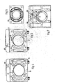
- FIG. 1 shows a longitudinal section
- FIG. 4 shows a cross section according to II-II in Figure 1
- Figure 5 shows a cross section according to III-III in Figure 1
- Figure 6 shows a cross section according to IV-IV in Figure 1
- Figure 7 shows a cross section according to VV in Figure 1
- Figure 8 shows a section according to VI-VI in Figure 1 and thus a plan view of the housing of the directional control valve in Figure 1
- Figure 9 shows a section along VII-VII in Figure 1 and thus a bottom view of a control plate of the directional control valve according to Figure 1
- Figure 10 is a view of one of the control plate according to Figure 9 removed round cord seal
- Figure 11 is a bottom view of the housing of the directional valve according to Figure 1 according to arrow VIII
- Figure 12 shows a cross section through the control plate according to IX-IX in Figure 9, Figure 13 an A.
- FIG. 14 shows the switching symbol of a second directional valve, which is designed as a changeover valve with air return
- Figure 15 shows the correspondingly modified, right cover in longitudinal section
- Figure 16 shows the side view 15 in the direction of arrow X '
- FIG. 17 shows the symbol of a third directional valve, which is designed as a pulse valve with differential piston
- FIG. 18 shows the associated section according to IV-IV, but with different and converted components
- FIG. 19 the sense picture of a fourth directional valve, which is designed as a changeover valve with spring return
- Figure 20 shows the associated right cover for spring return
- Figure 21 shows the cover according to Figure 20 in the direction of arrow XI
- Figure 21 ' shows the symbol of a fifth directional valve, which is used as a solenoid valve 22 is the associated section according to II in FIG. 1, but with shifted components
- FIG. 23 shows the symbol for a sixth directional valve, which is designed as a solenoid valve with spring return
- FIG. 24 shows a seventh directional valve, which is designed as a magnetic pulse valve
- FIG. 25 shows a partial section through the housing with a flanged control plate corresponding to FIG. 7, but with the twisted mounting position of the round cord seal for external control air supply.
- the 5/2-way valve has a housing 11 which accommodates a longitudinally movable control slide 13 in a multi-part slide bush 12.
- the housing 11 is closed at the top by a control plate 14, on its left end face 15 by a first cover unit 16 and on its right end face 17 by a second cover unit 18.
- the cover units 16, 18 are drawn separately from the housing 11 for better understanding.
- the housing 11 has five working connections for the supply air (21), for a consumer (22, 24) and for on a base surface 19 lying opposite the control plate 14 the exhaust air (23, 25) and furthermore a first and a second control connection 26, 27. These connections 21 to 27 are designed in accordance with the ISO standard, as shown in FIG. 11.
- an approximately U-shaped control channel 29 runs from the left end surface 15 to the right end surface 17 (see FIG. 8).
- the bottom section of this U-shaped control channel 29 is formed by a central longitudinal groove 31 which extends parallel to the longitudinal axis of the control slide and to which the oblique grooves 32 and 33 forming the legs of the U are connected to the outside.
- the oblique grooves 32, 33 forming the legs are here strongly bent outwards and separated from the longitudinal groove 31 by webs 34, 35 in a sealing surface 36.
- a first transverse groove 37 and a second transverse groove 38 lie in the sealing plane 36 diametrically to the longitudinal groove 31 and separated therefrom.
- a bore 39 leads from the first transverse groove 37 to the working connection 21 for the supply air.
- a first longitudinal bore 41 leads from the second transverse groove 38 into the left end face 15 and there opens into a first arc groove 42, which extends approximately over a fifth of the circumference, as can be seen in more detail in the figure.
- a second longitudinal bore 43 leads from the end of the first oblique groove 32 into a second curved groove 44 on the end face 15.
- a third longitudinal bore 45 connects the first control connection 26 with a third curved groove 46 in the same end face 15 runs in the left end face 15 diametrically to the first arc groove 42, a fourth arc groove 47, which like the other arc grooves 42, 44, 46 are on the same diameter.
- all three longitudinal bores 41, 43, 45 lie on the corners of a rectangle and thus at the same time on the diameter mentioned.
- a kidney-shaped opening 48 on the same diameter, which is connected to a ventilation opening 49 in the control surface 28, as can be seen from FIGS. 1 and 8.
- All arc grooves 42, 44, 46, 47 and the opening 48 are separated from one another in the end face 15 by material webs.
- a fifth longitudinal bore 51 leads from the second oblique groove 33 into the right end face 17, where it opens into a fifth arc groove 52.
- the fifth longitudinal bore 51 is coaxial with the second longitudinal bore 43.
- a sixth longitudinal bore 53 leads from the second control connection 27 in a corresponding manner into a sixth arc groove 54 in the end face 17, the sixth longitudinal bore 53 being coaxial with the third longitudinal bore 45.
- In the end face 17 there is a second kidney-shaped opening 55 between the two arc grooves 52 and 54, which is connected in a corresponding manner to a vent opening 56 in the control plane 28.
- the arc grooves 52, 54 and the opening 55 lie on the same diameter as the arc grooves on the other end face 15, the longitudinal bores 51 and 53 and their associated arc grooves 52 and 54 being arranged diametrically to one another.
- the fifth arch groove 52 extends over a circumferential section in which the first arch groove 42 and the third arch groove 46 run together in the left end face 15.
- the sixth Arch groove 54 As FIG. 8 shows in more detail, the ventilation openings 49 and 56 lie in the same longitudinal plane in the housing 11.
- FIG. 9 shows, in conjunction with FIGS. 1, 7 and 12, the construction of the control plate 14.
- a material web 61 can be seen in the control plate 14 designed as a die-cast part, the shape of which is adapted to the sealing surface 36 on the housing 11.
- this material web 61 there is a receiving surface 62 opposite the control surface 28, into which a preformed round cord seal 63 according to FIG. 10 can be inserted.
- a total of six elevations 64, 65, 66, 67, 59, 60 and two depressions 68, 69 are formed in the area of the receiving surface 62, the course and position of the grooves 31, 32, 33, 37, 38 in the sealing surface 36 of the housing 11 correspond.
- the elevations 64 to 67, 59, 60 protrude into the control plane 28 and ensure a perfect chambering of the round cord seal 63.
- a first (64) and a second elevation 65 of the longitudinal groove 31 lie opposite, the third elevation 66 of the first oblique groove 32 and the fourth elevation 67 of the second oblique groove 33.
- the first depression 68 and the fifth elevation 59 are assigned to the first transverse groove 37 and the second depression 69 with the sixth elevation 60 to the second transverse groove 38.
- the first (64) and the third elevation 66 can be connected to one another via a pair of holes 71 and a screwed-on manhole cover 72.
- a corresponding connection between the second (65) and the fourth elevation 67 enables a pair of bores 73 with associated channel cover 74.
- FIG. 10 shows the preformed round cord seal 63 removed from the control plate 14. Its round material essentially encloses the shape of two bars crossing in the middle, the ends of the longer cross bar being angled toward the same side in accordance with the course of the oblique grooves 32 and 33 in the housing 11.
- Two sealing cord webs 75 and 76 parallel to one another and a longitudinal cord web 77 lying at the point of intersection of the beams separate a P-chamber 78 in the circular cord seal from two outer, angled end chambers 79, 81 and from a transverse chamber 82
- a locking knob 83 see FIG.
- a display cam 84 is formed on the round cord seal 63 at one end of the long bar, which protrudes in the area of the control surface 28 between the housing 11 and the control plate 14 and, together with a mark 85 on the control plate 14, indicates the air supply for the control side.
- the round cord seal 63 is symmetrical to the extent that it is rotated by 180 from the position shown in FIG.
- the indicator cam 84 lies at a mark 86 for external air supply, which can be seen in FIG. 4. Since the entire seal 63 is made of round cord material, the pre-shaped, angled ends in one direction can easily be countered set direction are angled and inserted into the receiving surface 62.
- the first cover unit 16 flanged to the housing 11 on the left end face 15 is explained with reference to FIGS. 1 and 3. It consists essentially of an aluminum die-cast outer cover 87 which accommodates in its interior a bushing 88 formed as a plastic part, in which a drive piston 89 for the control slide 13 is tightly and slidably guided.
- the bushing 88 is essentially cup-shaped and has a flange 91 near its open end, on one side of which the cover 87 is supported with its edge 92.
- grooves 93 are formed for receiving an annular round cord seal 94.
- an arc-shaped groove 95 and the opening of a control channel 96 lie open in the bushing 88 towards the round cord seal, as can be seen from FIG. 3 and FIG. 13.
- the arcuate groove 95 is designed according to position and size so that depending on the mounting position of the lid unit 16 on the housing 11, a connection between the first (42) and the third arc groove 46 or a connection between the second arc groove 44 and the fourth arc groove 47 can produce.
- the opening of the control channel 96 lies essentially diametrically opposite the groove 95 in the flange 91.
- the control channel 96 opens with its end opposite the flange 91 into a pressure chamber 97 which lies between the drive piston 89 and a bottom of the cup-shaped bushing 88. Further points the bushing 88 from its open end to the sealing area of the round cord seal 94 extending longitudinal grooves 99, which serve to vent the rear side of the drive piston 89.
- the cup-shaped bushing 88 has stiffening ribs 101 running radially on the outside and has asymmetrical material accumulations 102 in the area of the control channel 96 and the arcuate groove 95, so that the bushing 88 only in one position the cover 87 can be used.
- the cover 87 with the inserted bushing 88 is so rotationally symmetrical with respect to the longitudinal axis of the control slide 13 that it can be mounted on the housing 11 in two installation positions rotated by 180 ° with respect to one another.
- FIG. 3 shows the round cord seal 9h inserted in the flange 91, which essentially consists of two concentric, essentially circular cord rings 103 and 104, which are kept apart by four radially extending cord webs 105 to 108 and an intermediate flat web 109 and in which the inner cord ring 103 is interrupted in a region diametrically opposite the flat web 109 to control ventilation.
- the annular cord seal 94 can only be inserted into the grooves 93 in the correct direction.
- the position of the diametrically opposed cord webs 105 and 107 is selected such that they come to lie in the end face 15 between the arc grooves 42 and 46 or 44 and 47 in each mounting position, while the groove 107 bridges the sealing point in question. Furthermore, the round cord seal 94 is so large that the inner cord ring 103 just spans the outer diameter of the bushing 88. The distance between the cord rings 103 and 104 is chosen so large that the openings and arc grooves lying on the same diameter are sealed from one another or connected to one another in the desired manner both in the end face 15 and in the flange 91 of the bushing 88.
- the O-seal 94 is formed rotationally symmetrical so far that in the grooves 93 of the flange, they can be inserted rotated from the drawn in Figure 3 by 180 0 91, wherein the flat web 91 comes to lie above.
- the right cover unit 18 consists of the same parts as the left cover unit 16, namely the outer cover 87 made of die-cast, the inner bushing 88 made of plastic, the working piston 89 arranged therein and the annular round cord seal 94.
- the cover is 87 rotated by 180 ° with bushing 88 mounted in a second installation position, while the round cord seal 94 maintains the same position as in FIG. 3.
- the directional control valve 1 As shown in Figure 2 is apparent, the directional control valve 1 '0 89. If the spool 13 operates as a pulse valve with the same piston areas of the working piston from the drawn in Figure 1, left-hand position to be moved to the right , a compressed air pulse is entered into the first control connection 26. This passes through the third longitudinal bore 45 into the third arcuate groove 46, which is defined by the annular round cord device 94 is tightly enclosed in the left end face 15 and directly via the control channel 96 in the socket 88 in the pressure chamber 97. The compressed air pushes the working piston 89 in the first cover unit 16 together with the control slide 13 to the right.
- An annular space 112 lying behind the working piston 89 and adjoining the control slide 13 is here via the longitudinal groove 99 lying above, the interruption in the inner cord ring 103 of the annular round cord seal 94, the kidney-shaped opening 48 in the left end face 15 and the vent opening 49 relieved to the outside air.
- outside air is sucked into the corresponding annular space 113 by the working piston 89 in the second cover unit 18 via the corresponding connection (56, 55, 99).
- the pressure chamber 97 in the second cover unit 18 is vented via the control channel 96 in the bushing 88 and the sixth arc groove 54 running in the end face 17 and sealed by the round cord seal 94 to the sixth longitudinal bore 53 and to the second control connection 27.
- control slide 13 When the control slide 13 is reversed from a right-hand end position into its left-hand end position, the control pulse is given in a correspondingly reverse manner into the second control connection 27, while the first control connection 26 is vented.
- the control slide 13 can thus produce the usual connections of a 5/2-way valve, as shown in FIG. 2 in a simplified manner.
- the left cover unit 16 on the housing 11 remains unchanged, while one instead of the second cover unit 18 according to FIG second cover unit 114 according to FIG. 15 is used.
- the cover unit 114 differs from that according to FIG. 1 primarily in that a spacer 115 is inserted into the bushing 88 instead of the drive piston 89.
- the cover 87, the bushing 88 and the round cord seal 94 remain unchanged, but are mounted together on the right end face 17 rotated by 180 ° about their longitudinal axis. This can be seen more clearly from FIG. 16 in comparison to FIG.
- the pressure acting on the longitudinal cord web 77 is transmitted to the control plate via the integrally formed securing cams 83 which protrude into the second recess 69 of the control plate 14, so that a perfect seal of the longitudinal groove 31 and the first transverse groove 37 is ensured.
- the compressed air passes through an open connection in the manhole cover 74 into the second oblique groove 33 and further into the fifth longitudinal bore 51.
- FIG. 5 shows in more detail, the compressed air can flow downward from there in the fifth arch groove 52, where it passes through the round cord seal 94 into the control channel 96 and further into the pressure chamber 97 of the second cover unit 114.
- the outlet opening 55 is in the region through a section of the inner cord ring 103 of the flat web 109 separated from the pressure chamber 97.
- the supply air in the longitudinal groove 31 passes through the first duct cover 72, the first oblique groove 32, the second longitudinal bore 43, the second arc groove 44, and the kidney-shaped groove 95 in the bushing 88 further into the fourth arc groove 47 in the end face 15, where it otherwise blocked by the annular cord seal 94.
- the control slide 13 of the directional control valve 10 is thus moved to the right into its end position by a pressure pulse in the first control connection 26, whereby it comes to rest on the spacer 115.
- the restoring force acting on the control slide 13 is the pressure from the working connection 21 in the pressure chamber 97 of the second cover unit 114 and thus on the control slide 13.
- the directional control valve 10 is now operated as a pulse valve with a differential piston, as is shown in simplified form in FIG. 17, the first cover unit 16 remains on the left end face 15, while the second cover unit 114 according to FIG. 15 is flanged onto the right end face 17, whereby, however, the lid 87 is rotated with an inserted bushing 88 in relation to Figure 16 to 180 0 to the longitudinal axis, the annular O-seal 94, however, maintains the position shown in Figure 16 position, as this is figure 18 in more detail.
- the first cover unit 16 remains on the housing 11, while a second cover unit 116 according to FIG. 20 is arranged on the right end face 17.
- the cover unit 116 differs from the second cover unit 18 according to FIG. 1 primarily by another bushing 117, from which only the bottom 98 has been removed, so that the bushing 117 accommodates a spring 118 with an associated pressure pin 119 for the spring return of the control slide 13 can.
- the cover 87 is identical in construction and is designed such that the spring 118 supported on it is centered. The bushing 117 can only be inserted into the cover 87 in a certain position due to its similar material thickenings 102.
- FIG. 21 The mounting position of the bushing 117 with the inserted round cord seal 94 is shown in FIG. 21, according to which the control air connections in the right end face are comparable to those in FIG. 6.
- the pressure chamber 97 receiving the spring 118 is vented via the openings 55 (FIG. 5) and 56.
- the connection to terminal 27 is blocked by a ball in socket 117.
- the control slide 13 can thus be deflected to the right by a control pulse in the first control connection 26 against the force of the spring 108, into an end position from which the spring 118 returns it to its left end position in the absence of control air.
- the directional control valve 10 is operated as a solenoid valve with air return, as shown in FIG. 21 'in a simplified manner, the following changes must be made compared to FIG. 1 be taken.
- the bushing 88 is rotated by 180 ° with respect to FIG. 3, while the round cord seal 94 maintains the position shown in FIG. 3.
- the manhole cover 72 is replaced by a 3/2-way solenoid valve which is not shown and is known per se.
- the second cover unit 114 according to FIGS. 15 and 16 is attached to the right end face 17 of the housing 11.
- FIG. 23 shows an operating mode of the directional valve 10 as a solenoid valve with spring return, the first cover unit 16 being arranged on the housing in the manner shown in FIG. 22, while on the opposite end face 17 the second cover unit i16 according to FIG. 20 is shown in the one shown in FIG Art is grown on the housing 11.
- FIG. 24 shows, as a further operating mode of the directional control valve 10, a magnetic pulse valve in a simplified representation, in which, based on FIG. 1, the following changes are necessary: the two manhole covers 72 and 74 on the control plate 14 must each be replaced by a 3/2 solenoid valve.
- the first cover unit 16 is flanged to the left end face 15 such that the bushing 88 and the round cord seal 94 assume the assembly positions shown in FIG.
- the end face 17 is attached to the second cover unit 18, but the bushing 88 and the round cord seal 94 assume the mounting positions shown in FIG. 3. With such an assembly, the directional control valve 10 can then be operated as a magnetic pulse valve.
- FIG. 25 shows a partial section according to FIG. 7, but the round cord seal 63 located in the control surface 28 is mounted in a different position in order to obtain a supply of external air to the control side.
- This position is achieved in that the round cord seal 63 according to FIG. 10 is rotated in the drawing plane by 180 ° about a vertical axis through the crossing point of the bars enclosed by the seal 63 and is thus placed in the receiving surface 62 of the control plate 14, with the securing cam 83 engages in the first recess 68 of the control plate.
- the second transverse groove 38 is then connected to the longitudinal groove 31 through the T-shaped chamber 78 of the circular cord seal 63, while the first transverse groove 37 is blocked.
- the securing cam 63 also prevents the longitudinal cord web 77 from being pressed out of its position under pressure in the longitudinal groove 31, so that a secure seal is ensured even when the external air supply is installed.
- the round cord seal 63 is installed in the control plate, 4 in the position suitable for supplying external air, the outer legs of the round cord seal 63 pointing in the opposite direction can easily be bent and inserted into the receiving surface 62.
- the installation position of the round cord seal 63 protrudes from the housing at the mark 86 for external air supply, but this is not shown in FIG. 4 provided for internal air supply.
Landscapes
- Engineering & Computer Science (AREA)
- General Engineering & Computer Science (AREA)
- Mechanical Engineering (AREA)
- Physics & Mathematics (AREA)
- Electromagnetism (AREA)
- Fluid Mechanics (AREA)
- Multiple-Way Valves (AREA)
- Quick-Acting Or Multi-Walled Pipe Joints (AREA)
Applications Claiming Priority (2)
| Application Number | Priority Date | Filing Date | Title |
|---|---|---|---|
| DE19823216705 DE3216705A1 (de) | 1982-05-05 | 1982-05-05 | Wegeventil |
| DE3216705 | 1982-05-05 |
Publications (2)
| Publication Number | Publication Date |
|---|---|
| EP0093359A1 true EP0093359A1 (fr) | 1983-11-09 |
| EP0093359B1 EP0093359B1 (fr) | 1986-07-23 |
Family
ID=6162700
Family Applications (1)
| Application Number | Title | Priority Date | Filing Date |
|---|---|---|---|
| EP83104002A Expired EP0093359B1 (fr) | 1982-05-05 | 1983-04-23 | Tiroir cylindrique à voies multiples |
Country Status (2)
| Country | Link |
|---|---|
| EP (1) | EP0093359B1 (fr) |
| DE (2) | DE3216705A1 (fr) |
Cited By (5)
| Publication number | Priority date | Publication date | Assignee | Title |
|---|---|---|---|---|
| FR2620191A1 (fr) * | 1987-03-31 | 1989-03-10 | Telemecanique Electrique | Distributeur a tiroir universel |
| EP0468606A1 (fr) * | 1990-07-24 | 1992-01-29 | MANNESMANN Aktiengesellschaft | Tiroir multifonctionnel à plusieurs voies |
| DE4039564C1 (fr) * | 1990-12-07 | 1992-03-12 | Mannesmann Ag, 4000 Duesseldorf, De | |
| US6186174B1 (en) | 1997-10-01 | 2001-02-13 | Muskin Leisure Products, Inc. | Valve assembly |
| WO2016135012A1 (fr) * | 2015-02-25 | 2016-09-01 | Knorr-Bremse Systeme für Nutzfahrzeuge GmbH | Dispositif à fluide sous pression comprenant des liaisons d'écoulement variables en raison de joints profilés |
Citations (4)
| Publication number | Priority date | Publication date | Assignee | Title |
|---|---|---|---|---|
| GB1152472A (en) * | 1965-12-08 | 1969-05-21 | P S I Ltd | Improvements in or relating to Spool Valves For Controlling Fluid Flow |
| DE1917598A1 (de) * | 1969-04-05 | 1970-10-15 | Christian Buerkert Bau Elek Sc | Wegeventil |
| FR2257837A1 (en) * | 1973-08-28 | 1975-08-08 | Wabco Westinghouse | Spool type distributor for pressure fluid - has apertured selector plate controlling pilot fluid and line flow |
| FR2339115A1 (fr) * | 1976-01-26 | 1977-08-19 | Jouvenel & Cordier | Distributeur a tiroir |
Family Cites Families (1)
| Publication number | Priority date | Publication date | Assignee | Title |
|---|---|---|---|---|
| DE7035256U (de) * | 1970-09-23 | 1972-03-02 | Bosch Gmbh Robert | Steuerventil. |
-
1982
- 1982-05-05 DE DE19823216705 patent/DE3216705A1/de not_active Withdrawn
-
1983
- 1983-04-23 DE DE8383104002T patent/DE3364670D1/de not_active Expired
- 1983-04-23 EP EP83104002A patent/EP0093359B1/fr not_active Expired
Patent Citations (4)
| Publication number | Priority date | Publication date | Assignee | Title |
|---|---|---|---|---|
| GB1152472A (en) * | 1965-12-08 | 1969-05-21 | P S I Ltd | Improvements in or relating to Spool Valves For Controlling Fluid Flow |
| DE1917598A1 (de) * | 1969-04-05 | 1970-10-15 | Christian Buerkert Bau Elek Sc | Wegeventil |
| FR2257837A1 (en) * | 1973-08-28 | 1975-08-08 | Wabco Westinghouse | Spool type distributor for pressure fluid - has apertured selector plate controlling pilot fluid and line flow |
| FR2339115A1 (fr) * | 1976-01-26 | 1977-08-19 | Jouvenel & Cordier | Distributeur a tiroir |
Cited By (11)
| Publication number | Priority date | Publication date | Assignee | Title |
|---|---|---|---|---|
| FR2620191A1 (fr) * | 1987-03-31 | 1989-03-10 | Telemecanique Electrique | Distributeur a tiroir universel |
| EP0468606A1 (fr) * | 1990-07-24 | 1992-01-29 | MANNESMANN Aktiengesellschaft | Tiroir multifonctionnel à plusieurs voies |
| US5273074A (en) * | 1990-07-24 | 1993-12-28 | Mannesmann Aktiengesellschaft Gmbh | Multifunction multiport slider valve |
| DE4039564C1 (fr) * | 1990-12-07 | 1992-03-12 | Mannesmann Ag, 4000 Duesseldorf, De | |
| US5236017A (en) * | 1990-12-07 | 1993-08-17 | Mannesmann Aktiengesellschaft | Distributing valve of modular construction |
| US6186174B1 (en) | 1997-10-01 | 2001-02-13 | Muskin Leisure Products, Inc. | Valve assembly |
| WO2016135012A1 (fr) * | 2015-02-25 | 2016-09-01 | Knorr-Bremse Systeme für Nutzfahrzeuge GmbH | Dispositif à fluide sous pression comprenant des liaisons d'écoulement variables en raison de joints profilés |
| CN107407302A (zh) * | 2015-02-25 | 2017-11-28 | 克诺尔商用车制动系统有限公司 | 具有基于成型密封件而可变的流动连接的压力介质装置 |
| JP2018508411A (ja) * | 2015-02-25 | 2018-03-29 | クノル−ブレムゼ ジステーメ フューア ヌッツファールツォイゲ ゲゼルシャフト ミット ベシュレンクテル ハフツングKnorr−Bremse Systeme fuer Nutzfahrzeuge GmbH | 成形シールに基づいて可変の流動接続を有する圧力媒体装置 |
| US10337534B2 (en) | 2015-02-25 | 2019-07-02 | Knorr-Bremse Systeme Fuer Nutzfahrzeuge Gmbh | Pressure medium device comprising fluidic connections which are variable on the basis of molded seals |
| CN107407302B (zh) * | 2015-02-25 | 2019-08-20 | 克诺尔商用车制动系统有限公司 | 具有基于成型密封件而可变的流动连接的压力介质装置 |
Also Published As
| Publication number | Publication date |
|---|---|
| DE3364670D1 (en) | 1986-08-28 |
| EP0093359B1 (fr) | 1986-07-23 |
| DE3216705A1 (de) | 1983-11-10 |
Similar Documents
| Publication | Publication Date | Title |
|---|---|---|
| DE2950888C2 (fr) | ||
| EP0279177B1 (fr) | Vanne à volume de fuite | |
| EP0629782B1 (fr) | Dispositif de commande pour une soupape à voies multiples | |
| DE3114437C2 (de) | Druckregelventil | |
| EP0719395B1 (fr) | Soupape modulaire pour milieux en ecoulement | |
| EP0688411A1 (fr) | Soupape de commande hydraulique | |
| EP0093360B1 (fr) | Vanne à voies multiples prévu pour des conditions d'opération différentes | |
| EP0198234B1 (fr) | Robinet-vanne fluidique à voies multiples | |
| EP0093359B1 (fr) | Tiroir cylindrique à voies multiples | |
| EP1281001B1 (fr) | Ensemble soupape pourvu d'un conduit d'ecoulement interne ayant un segment de longueur ouvert | |
| EP0676573B1 (fr) | Distributeur avec plaque de base | |
| DE2943714C2 (fr) | ||
| CH643042A5 (en) | Solenoid valve arrangement | |
| DE19839427A1 (de) | Mehrwege-Drehventil | |
| DE3337234A1 (de) | Ventileinrichtung mit einem piezoelektrischen oder magnetostriktiven stellglied | |
| EP0637708B1 (fr) | Distributeur à plusieurs voies particulièrement pour commande des moteurs pneumatiques | |
| DE10014906A1 (de) | Mehrwegeventil (Deckelbefestigung) | |
| EP0688958A1 (fr) | Arrangement de soupape | |
| DE102006062432A1 (de) | Modulares pneumatisches Schieberventil | |
| DE4318926C2 (de) | Mehrwegeventil | |
| DE4413216A1 (de) | Hydraulisches Wegeventil | |
| EP0102443A1 (fr) | Tiroir à voies multiples | |
| EP1310388B1 (fr) | Soupape de régulation de niveau pour maintenir constante automatiquement la hauteur d'un véhicule utilitaire à suspension pneumatique | |
| DE102012004296B4 (de) | Ventil zur Fluidsteuerung | |
| DE4206095A1 (de) | Wegeventil, insbesondere vier-wegeventil |
Legal Events
| Date | Code | Title | Description |
|---|---|---|---|
| PUAI | Public reference made under article 153(3) epc to a published international application that has entered the european phase |
Free format text: ORIGINAL CODE: 0009012 |
|
| 17P | Request for examination filed |
Effective date: 19830423 |
|
| AK | Designated contracting states |
Designated state(s): CH DE FR IT LI |
|
| GRAA | (expected) grant |
Free format text: ORIGINAL CODE: 0009210 |
|
| AK | Designated contracting states |
Kind code of ref document: B1 Designated state(s): CH DE FR IT LI |
|
| REF | Corresponds to: |
Ref document number: 3364670 Country of ref document: DE Date of ref document: 19860828 |
|
| ET | Fr: translation filed | ||
| ITF | It: translation for a ep patent filed | ||
| PLBE | No opposition filed within time limit |
Free format text: ORIGINAL CODE: 0009261 |
|
| STAA | Information on the status of an ep patent application or granted ep patent |
Free format text: STATUS: NO OPPOSITION FILED WITHIN TIME LIMIT |
|
| 26N | No opposition filed | ||
| ITTA | It: last paid annual fee | ||
| PGFP | Annual fee paid to national office [announced via postgrant information from national office to epo] |
Ref country code: CH Payment date: 19920717 Year of fee payment: 10 |
|
| PG25 | Lapsed in a contracting state [announced via postgrant information from national office to epo] |
Ref country code: LI Effective date: 19930430 Ref country code: CH Effective date: 19930430 |
|
| REG | Reference to a national code |
Ref country code: CH Ref legal event code: PL |
|
| PGFP | Annual fee paid to national office [announced via postgrant information from national office to epo] |
Ref country code: FR Payment date: 19950413 Year of fee payment: 13 |
|
| PGFP | Annual fee paid to national office [announced via postgrant information from national office to epo] |
Ref country code: DE Payment date: 19950621 Year of fee payment: 13 |
|
| PG25 | Lapsed in a contracting state [announced via postgrant information from national office to epo] |
Ref country code: FR Effective date: 19961227 |
|
| PG25 | Lapsed in a contracting state [announced via postgrant information from national office to epo] |
Ref country code: DE Effective date: 19970101 |
|
| REG | Reference to a national code |
Ref country code: FR Ref legal event code: ST |