EP0093391A2 - Gabarid de perçage pour le guidage d'un outil/foret - Google Patents
Gabarid de perçage pour le guidage d'un outil/foret Download PDFInfo
- Publication number
- EP0093391A2 EP0093391A2 EP83104115A EP83104115A EP0093391A2 EP 0093391 A2 EP0093391 A2 EP 0093391A2 EP 83104115 A EP83104115 A EP 83104115A EP 83104115 A EP83104115 A EP 83104115A EP 0093391 A2 EP0093391 A2 EP 0093391A2
- Authority
- EP
- European Patent Office
- Prior art keywords
- bores
- eccentric
- gauge
- bar
- drilling jig
- Prior art date
- Legal status (The legal status is an assumption and is not a legal conclusion. Google has not performed a legal analysis and makes no representation as to the accuracy of the status listed.)
- Withdrawn
Links
Images

Classifications
-
- B—PERFORMING OPERATIONS; TRANSPORTING
- B23—MACHINE TOOLS; METAL-WORKING NOT OTHERWISE PROVIDED FOR
- B23B—TURNING; BORING
- B23B47/00—Constructional features of components specially designed for boring or drilling machines; Accessories therefor
- B23B47/28—Drill jigs for workpieces
- B23B47/287—Jigs for drilling plate-like workpieces
Definitions
- the present invention relates to a drilling jig for guiding a tool / drill for producing eccentric bores, through-bores for eccentric pins and fastening bores for the eccentric pin in workpiece plates.
- Drilling takes place on the corresponding plate part and then the drilling is done by hand.
- this method of working is not particularly favorable in view of the time required.
- the through holes for the eccentric pins without the position of the gauge needing to be changed.
- the jig for drilling these two holes is placed on the workpiece to be drilled (bottom part, middle part, cover part), the first gauge bar lying flush on the workpiece surface side and the second gauge bar on one side of the workpiece face and a stop pin the position the holes are fixed opposite the other face of the workpiece.
- the gauge is clamped and the through holes for the eccentric pins are drilled in the front of the workpiece with a hand drill.
- the eccentric holes are then drilled in the workpiece surface side.
- the eccentric hole is made.
- the constant position of the gauge ensures that the eccentric hole and the through hole are exactly matched to each other in one plane.
- the distance between the center of the through hole and the sides of the workpiece surface can be predefined by arranging the through holes in the second gauge bar.
- a stop bar is preferably provided on the second gauge bar, with which the gauge is fixed / clamped on the workpiece surface side opposite the workpiece surface side in which the eccentric bore is provided. The distance between the through bores can then advantageously be changed by interchangeable disks.
- the drilling jig is then placed on the side part with the first gauge bar removed and positioned with a stop and the hole is drilled with a hand drill, so that the mounting hole in the side part and through hole in the base part etc. are precisely coordinated and the precise fitting can be done.
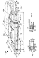
- the drilling jig for guiding a drill for making holes in furniture parts is designated 10.
- the drilling jig 10 the length of which is approximately 700 mm, has two gauge bars 11 and 12 arranged at right angles to one another.
- holes 13 are arranged for fixing / centering an E xzenterbohrungstechnikmaschinemaschinees.
- the bores 13 are at a distance 14 of 64 mm from one another and a diameter of 50 mm.
- the two outer bores 13a and 13b are at a distance 15 of 37 mm from a stop pin 16.
- the distance 17 (see Fig. 1.4) is 33 mm, but can advantageously also be made adjustable, e.g. over different holes 36.
- the second gauge bar 12 contains drill bushings 18, the distance 19 of which corresponds to the distance 14 of the bores 13. Furthermore, there are drill bushings 18, the spacing 19 of which corresponds to the spacing 14 of the bores 13. Furthermore, drill bushings 18 and bores 13 lie in the same plane A-A. In addition, 16 spacers of any length can be inserted into the two stop pins. This allows the distances 14 and 19 to be changed as desired and e.g. be drilled in a 32 grid.
- All drill sleeves are preferably designed as hardened steel drill sleeves and have an inner diameter of 8 mm.
- the gauge 10 also has a stop bar 23 which is fastened parallel to the first gauge bar 11 on the second gauge bar 12 + serving as a stop
- Interchangeable spacers 24 are attached between stop bar 23 and second gauge bar 12. Depending on the number and thickness is preferably 1 mm, and 0.5 of the spacers 24 and a distance mm 25 of drill bushings from the lower edge 26 of 8 mm any clearances 27 can (8 to 1 6 mm) in the end face 28 of the workpiece plate 29 (see Fig. also Fig. 2 and 4) can be achieved with different workpiece plate thicknesses (16 - 30 mm).
- the second gauge bar 12 preferably has a square cross section (20x20 mm) and is made of a light metal material.
- the gauge bar 11 and the stop bar 23 are preferably made of plastic and have a thickness "S" of approximately 10 mm, a length "L” of approximately 700 mm and a width "BR" of approximately 100 mm (gauge bar 11) or 53 mm (stop bar 23). It is of course also possible to produce the strips 11 and 23 from light metal material.
- the gauge bars 11 and 12 and the stop bar 23 are connected by screws 36.
- the drilling jig 10 has a symmetrical, mirror-image drilling pattern, so that any side of a furniture panel of any length can be drilled with the same teaching.
- the teaching is struck either on the right or left, in which case either one or the other stop pin 16 is used.
- the right pin 16 is partially pulled out and not in use.
- the stop pins 16 are slidably arranged in the drill bushings 20 (see also FIG. 3).
- the gauge 10 can also be used advantageously.
- a through hole that has already been drilled in the end face is then used to receive the stop pin 16 and to fix the gauge.
- one or more eccentric bores 30 and correspondingly one or more through bores 31 can be produced with the gauge 10 in one position.
- the teaching, as shown in FIG. 4 is clamped against the lower plate surface side 32 with the stop bar 23 and then the eccentric bore 30 is drilled.
- a thrust ring of a router or a drilling machine into the bore 13 for fixing a pot drill and to produce the pot bore.
- the thrust ring also has a diameter of 50 mm, while the pot drill has an outer diameter of 25 mm, so that an eccentric pot bore with a diameter of 25 mm or any diameter can be drilled / milled in the plate.
- the through hole 31 is then produced, a drill being passed through the drill bushing 18.
Landscapes
- Engineering & Computer Science (AREA)
- Mechanical Engineering (AREA)
- Drilling And Boring (AREA)
Applications Claiming Priority (2)
| Application Number | Priority Date | Filing Date | Title |
|---|---|---|---|
| DE19823215957 DE3215957C2 (de) | 1982-04-29 | 1982-04-29 | Bohrlehre zum Führen eines Werkzeuges/Bohrers |
| DE3215957 | 1982-04-29 |
Publications (2)
| Publication Number | Publication Date |
|---|---|
| EP0093391A2 true EP0093391A2 (fr) | 1983-11-09 |
| EP0093391A3 EP0093391A3 (fr) | 1984-09-05 |
Family
ID=6162255
Family Applications (1)
| Application Number | Title | Priority Date | Filing Date |
|---|---|---|---|
| EP83104115A Withdrawn EP0093391A3 (fr) | 1982-04-29 | 1983-04-27 | Gabarid de perçage pour le guidage d'un outil/foret |
Country Status (2)
| Country | Link |
|---|---|
| EP (1) | EP0093391A3 (fr) |
| DE (1) | DE3215957C2 (fr) |
Cited By (5)
| Publication number | Priority date | Publication date | Assignee | Title |
|---|---|---|---|---|
| EP0211135A3 (en) * | 1985-08-09 | 1988-08-17 | Schedel Eduard Gmbh | Drilling jig |
| FR2617420A1 (fr) * | 1987-07-02 | 1989-01-06 | Irrigaray Jean | Dispositif de guidage pour operation de percage et chevillage |
| US8128321B2 (en) * | 2006-01-24 | 2012-03-06 | Peter Quinn | Drilling templates |
| CN102699386A (zh) * | 2012-05-31 | 2012-10-03 | 安徽蓝博旺机械有限责任公司 | 一种控制阀阀体斜孔钻模工装 |
| CN109926626A (zh) * | 2019-03-01 | 2019-06-25 | 武汉船用机械有限责任公司 | 板状零件加工工装 |
Family Cites Families (4)
| Publication number | Priority date | Publication date | Assignee | Title |
|---|---|---|---|---|
| US3048062A (en) * | 1959-09-23 | 1962-08-07 | Ira C Bass | Lock installing tool |
| DE7013651U (de) * | 1970-04-07 | 1970-12-23 | Heyn Georg | Duebel-bohrlehre universeller art. |
| DE3104973A1 (de) * | 1981-02-12 | 1982-08-26 | Breuer & Schmitz, 5650 Solingen | "aufschraubband, insbesondere fuer schwere fenster- oder tuerfluegel mit kunststoffprofilen" |
| DE8132763U1 (de) * | 1981-11-10 | 1982-04-15 | Häfele KG, 7270 Nagold | "Bohrlehre" |
-
1982
- 1982-04-29 DE DE19823215957 patent/DE3215957C2/de not_active Expired
-
1983
- 1983-04-27 EP EP83104115A patent/EP0093391A3/fr not_active Withdrawn
Cited By (6)
| Publication number | Priority date | Publication date | Assignee | Title |
|---|---|---|---|---|
| EP0211135A3 (en) * | 1985-08-09 | 1988-08-17 | Schedel Eduard Gmbh | Drilling jig |
| FR2617420A1 (fr) * | 1987-07-02 | 1989-01-06 | Irrigaray Jean | Dispositif de guidage pour operation de percage et chevillage |
| US8128321B2 (en) * | 2006-01-24 | 2012-03-06 | Peter Quinn | Drilling templates |
| CN102699386A (zh) * | 2012-05-31 | 2012-10-03 | 安徽蓝博旺机械有限责任公司 | 一种控制阀阀体斜孔钻模工装 |
| CN102699386B (zh) * | 2012-05-31 | 2014-05-07 | 安徽蓝博旺机械集团液压流体机械有限责任公司 | 一种控制阀阀体斜孔钻模工装 |
| CN109926626A (zh) * | 2019-03-01 | 2019-06-25 | 武汉船用机械有限责任公司 | 板状零件加工工装 |
Also Published As
| Publication number | Publication date |
|---|---|
| DE3215957C2 (de) | 1986-08-21 |
| DE3215957A1 (de) | 1983-11-10 |
| EP0093391A3 (fr) | 1984-09-05 |
Similar Documents
| Publication | Publication Date | Title |
|---|---|---|
| DE69512488T2 (de) | Keilzinkenschablone | |
| DE3046922C2 (de) | Druckluft-Handbohrmaschine | |
| DE3105180A1 (de) | Werkzeug zum verduebeln | |
| DE3306563C2 (de) | Bohrhilfsgerät | |
| DE3215957C2 (de) | Bohrlehre zum Führen eines Werkzeuges/Bohrers | |
| EP0050210A2 (fr) | Gabarit de perçage | |
| DE19844516C2 (de) | Tragbare Vorrichtung zur Erstellung von Dübellöchern und/oder Ausfräsungen | |
| DE3625608A1 (de) | Spannvorrichtung fuer ein werkzeug an einer werkzeugmaschine, insbesondere einer senkerodiermaschine | |
| DE3108290C2 (de) | Bohrlehre | |
| DE2542346C3 (de) | Innenräumwerkzeug, insbesondere zur Herstellung von Profilnuten | |
| DE656738C (de) | Stanz- und Schnittwerkzeug mit auswechselbaren Schnittplatten | |
| EP0413203B1 (fr) | Dispositif de perçage | |
| DE2604874B2 (de) | Einrichtung zum einpassen von druckplatten fuer offset-rollen-rotationsdruckmaschinen | |
| DE202012101301U1 (de) | Fräsführung für ein Fräswerkzeug sowie Frässchablone zur Verwendung in einer Fräsführung | |
| DE3435379A1 (de) | Vorrichtung und verfahren zum herstellen von loechern in kunststoff-hohlprofilstaeben | |
| DE3828482C2 (de) | Stoss- oder Ziehwerkzeug | |
| DE3537992A1 (de) | Oberfraesenfuehrer fuer eine gitterartige zinkenfraeslehre | |
| DE10310852B3 (de) | Vorrichtung zum Prägen und/oder Stanzen eines Werkstücks, insbesondere aus Kartonage | |
| DE3442102A1 (de) | Spannschaft und dazugehoeriger schneidentraeger | |
| DE2500620A1 (de) | Zerspanungswerkzeug | |
| DE3005639A1 (de) | Spannvorrichtung bei funkenerosiven werkzeugmaschinen o.dgl. | |
| DE2841866C2 (de) | Folgeschnittwerkzeug für Stanzmaschinen | |
| DE2152810B2 (de) | Vorrichtung zur Befestigung eines Zifferblattes auf einem Uhrwerk | |
| DE20303948U1 (de) | Vorrichtung zum Prägen und/oder Stanzen eines Werkstücks | |
| DE8132763U1 (de) | "Bohrlehre" |
Legal Events
| Date | Code | Title | Description |
|---|---|---|---|
| PUAI | Public reference made under article 153(3) epc to a published international application that has entered the european phase |
Free format text: ORIGINAL CODE: 0009012 |
|
| AK | Designated contracting states |
Designated state(s): AT BE CH FR GB IT LI NL SE |
|
| PUAL | Search report despatched |
Free format text: ORIGINAL CODE: 0009013 |
|
| AK | Designated contracting states |
Designated state(s): AT BE CH FR GB IT LI NL SE |
|
| STAA | Information on the status of an ep patent application or granted ep patent |
Free format text: STATUS: THE APPLICATION IS DEEMED TO BE WITHDRAWN |
|
| 18D | Application deemed to be withdrawn |
Effective date: 19850506 |