EP0093414A2 - Tube interrupteur à vide - Google Patents
Tube interrupteur à vide Download PDFInfo
- Publication number
- EP0093414A2 EP0093414A2 EP83104183A EP83104183A EP0093414A2 EP 0093414 A2 EP0093414 A2 EP 0093414A2 EP 83104183 A EP83104183 A EP 83104183A EP 83104183 A EP83104183 A EP 83104183A EP 0093414 A2 EP0093414 A2 EP 0093414A2
- Authority
- EP
- European Patent Office
- Prior art keywords
- flange
- vacuum
- ring
- vacuum interrupter
- elastically
- Prior art date
- Legal status (The legal status is an assumption and is not a legal conclusion. Google has not performed a legal analysis and makes no representation as to the accuracy of the status listed.)
- Granted
Links
Images
Classifications
-
- H—ELECTRICITY
- H01—ELECTRIC ELEMENTS
- H01H—ELECTRIC SWITCHES; RELAYS; SELECTORS; EMERGENCY PROTECTIVE DEVICES
- H01H33/00—High-tension or heavy-current switches with arc-extinguishing or arc-preventing means
- H01H33/60—Switches wherein the means for extinguishing or preventing the arc do not include separate means for obtaining or increasing flow of arc-extinguishing fluid
- H01H33/66—Vacuum switches
- H01H33/662—Housings or protective screens
- H01H33/66207—Specific housing details, e.g. sealing, soldering or brazing
- H01H2033/66215—Details relating to the soldering or brazing of vacuum switch housings
-
- H—ELECTRICITY
- H01—ELECTRIC ELEMENTS
- H01H—ELECTRIC SWITCHES; RELAYS; SELECTORS; EMERGENCY PROTECTIVE DEVICES
- H01H33/00—High-tension or heavy-current switches with arc-extinguishing or arc-preventing means
- H01H33/60—Switches wherein the means for extinguishing or preventing the arc do not include separate means for obtaining or increasing flow of arc-extinguishing fluid
- H01H33/66—Vacuum switches
- H01H33/662—Housings or protective screens
- H01H33/66207—Specific housing details, e.g. sealing, soldering or brazing
- H01H2033/66223—Details relating to the sealing of vacuum switch housings
Definitions
- the invention relates to a vacuum interrupter according to the preamble of claim 1.
- a vacuum interrupter is known from US Pat. No. 3,231,704.
- the elastic ring has a solder flange and an adjacent cylinder jacket.
- the cylinder jacket absorbs different shape changes due to heat fluctuations, while the solder flange follows the changes in the dimensions of the ceramic tube due to its small wall thickness.
- US-PS 3082307 corrugated connection flanges can be found for fastening ceramic tubes to a stud bolt of a vacuum interrupter.
- this patent does not contain any reference to an elastic connection between the stud and the housing.
- the object on which the present invention is based is to increase the inrush current of a vacuum interrupter according to the preamble of claim 1.
- the vacuum interrupter according to the invention is insensitive to longitudinal vibrations and bending vibrations which can occur as a result of a switching operation. It therefore requires considerably less effort to dampen the switch pole vibrations when installed in a circuit breaker.
- the elastically deformable ring is advantageously designed to be flat if the greatest possible mobility in both directions is desired. It can also have the shape of a truncated cone, the smaller surface of which advantageously faces the soldering flange when through the vacuum forces exerted on the flange are to be absorbed by the flange in the form of stresses
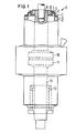
- Fig. 1 shows a switching tube according to the invention in a partially cut and broken view.
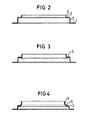
- FIGS. 2 and 3 show two embodiments of a flange according to the invention.
- a switching tube has contacts 10 and 11 which are aligned with one another, of which the fixed contact is fastened to a stud 9.
- an elastic flange 8 is attached via a housing ring 12, which carries a ceramic ring 7 and thus the entire housing of the vacuum interrupter.
- the elastic flange 8 is composed of a solder flange 1, a cylinder wall 2, an elastically easily deformable ring 3 and a cylindrical part 4.
- the solder flange 1 is brazed to the metallized end face 6 of the ceramic tube 7.
- An Agcu eutectic advantageously serves as the solder.
- the cylinder wall 2 is stiff due to its shape when the housing vibrates in or perpendicular to the direction of the housing axis, it does not take part in these vibrations appreciably, a disturbance of its lattice structure by the solder does not affect the life of the tube, even if this means at least in the area , which is adjacent to the solder flange, embrittlement of the material occurs.
- the elastic, easily deformable ring 3 is free from such a disturbance of the lattice structure.
- the adjoining cylindrical Tei1 4 is welded to the housing ring 12. This means that there is no disruption to the lattice structure since, unlike soldering, no foreign metals are fed in during welding will.
- the weld is advantageously carried out only in the forehead area, the remaining, not welded part of the ring also gives a distance from the elastically deformable ring.
- the movable contact 11 is connected to the housing in a vacuum-tight manner via a bolt 13 and a bellows 12.
- the elastically easily deformable ring 3 is flat according to FIG. 2. It therefore ensures a particularly high degree of mobility in the axial directions.
- the elastically easily deformable ring 5 is frustoconical, the smaller cut surface of the truncated cone facing the solder flange 1.
- This embodiment absorbs the compressive force exerted on the housing as a result of the vacuum inside the tube as tensile stress.
- This embodiment enables a particularly thin wall thickness of the flange 8.
- the curved region 6 has an arcuate cross section. This embodiment has proven to be particularly stable and advantageous with the vibrations that occur.
Landscapes
- High-Tension Arc-Extinguishing Switches Without Spraying Means (AREA)
Applications Claiming Priority (3)
| Application Number | Priority Date | Filing Date | Title |
|---|---|---|---|
| DE19828212546 DE8212546U1 (de) | 1982-04-30 | 1982-04-30 | Vakuumschaltröhre |
| DE19823216251 DE3216251A1 (de) | 1982-04-30 | 1982-04-30 | Vakuumschaltroehre |
| DE3216251 | 1982-04-30 |
Publications (3)
| Publication Number | Publication Date |
|---|---|
| EP0093414A2 true EP0093414A2 (fr) | 1983-11-09 |
| EP0093414A3 EP0093414A3 (en) | 1985-05-15 |
| EP0093414B1 EP0093414B1 (fr) | 1987-09-23 |
Family
ID=25801479
Family Applications (1)
| Application Number | Title | Priority Date | Filing Date |
|---|---|---|---|
| EP83104183A Expired EP0093414B1 (fr) | 1982-04-30 | 1983-04-28 | Tube interrupteur à vide |
Country Status (4)
| Country | Link |
|---|---|
| US (1) | US4497990A (fr) |
| EP (1) | EP0093414B1 (fr) |
| JP (1) | JPS58198811A (fr) |
| DE (1) | DE3216251A1 (fr) |
Cited By (1)
| Publication number | Priority date | Publication date | Assignee | Title |
|---|---|---|---|---|
| DE3803778A1 (de) * | 1988-02-09 | 1989-08-17 | Licentia Gmbh | Vakuumschaltkammer |
Families Citing this family (8)
| Publication number | Priority date | Publication date | Assignee | Title |
|---|---|---|---|---|
| DE3325468A1 (de) * | 1983-07-14 | 1985-01-24 | Siemens AG, 1000 Berlin und 8000 München | Gehaeuse einer vakuumschaltroehre |
| US4831327A (en) * | 1987-05-01 | 1989-05-16 | Hydro-Quebec | Self-powered electrical measuring system isolated from electrical perturbances |
| DE3825407A1 (de) * | 1988-07-27 | 1990-02-01 | Sachsenwerk Ag | Schaltkammer eines vakuumschalters |
| GB2308497A (en) * | 1995-12-21 | 1997-06-25 | Gec Alsthom Ltd | Vacuum switching device |
| US6867385B2 (en) * | 2003-02-21 | 2005-03-15 | Mcgraw-Edison Company | Self-fixturing system for a vacuum interrupter |
| DE102015216911B4 (de) | 2015-09-03 | 2018-10-31 | Siemens Aktiengesellschaft | Vakuumschaltröhre mit einer Halteelementaufnahme und/oder einem Halteelement und Verfahren zum Herstellen einer solchen |
| DE102015217403A1 (de) | 2015-09-11 | 2017-03-16 | Siemens Aktiengesellschaft | Schaltgerät mit einer Vakuumröhre |
| DE202017104184U1 (de) | 2017-07-13 | 2018-10-16 | Conductix-Wampfler Gmbh | Vorrichtung zur Detektion eines Abnutzungszustandes eines Schleifkontakts |
Family Cites Families (14)
| Publication number | Priority date | Publication date | Assignee | Title |
|---|---|---|---|---|
| NL292339A (fr) * | ||||
| US3082307A (en) * | 1959-04-30 | 1963-03-19 | Gen Electric | Vacuum type circuit interrupter |
| NL275722A (fr) * | 1961-03-10 | |||
| GB1026054A (en) * | 1962-05-04 | 1966-04-14 | Ass Elect Ind | Improvements relating to vacuum electric devices |
| US3189715A (en) * | 1962-05-21 | 1965-06-15 | Jennings Radio Mfg Corp | Internal shield and seal structure for vacuum sealed switch envelope |
| US3166658A (en) * | 1962-07-05 | 1965-01-19 | Jennings Radio Mfg Corp | Vacuum switch and envelope construction therefor |
| US3196236A (en) * | 1962-07-16 | 1965-07-20 | Jennings Radio Mfg Corp | High power vacuum circuit breaker contacts and arc-extinguishing means therefor |
| CH436421A (de) * | 1963-04-09 | 1967-11-15 | Jennings Radio Manufacturing C | Leistungsschalter |
| US3261953A (en) * | 1963-10-10 | 1966-07-19 | Jennings Radio Mfg Corp | High power rf relay incorporating heatsink and fluid cooling |
| US3355564A (en) * | 1966-06-03 | 1967-11-28 | John W Ranheim | Vacuum-type circuit interrupter |
| DE2058020A1 (de) * | 1970-11-25 | 1972-05-31 | Siemens Ag | Vakuumschaltergehaeuse |
| DE2717562A1 (de) * | 1977-04-20 | 1978-10-26 | Siemens Ag | Verbindungsflanschring fuer vakuumschaltroehren |
| JPS5636011Y2 (fr) * | 1979-08-30 | 1981-08-25 | ||
| JPS56156626A (en) * | 1980-05-06 | 1981-12-03 | Meidensha Electric Mfg Co Ltd | Vacuum breaker |
-
1982
- 1982-04-30 DE DE19823216251 patent/DE3216251A1/de not_active Ceased
-
1983
- 1983-04-25 US US06/488,187 patent/US4497990A/en not_active Expired - Fee Related
- 1983-04-28 EP EP83104183A patent/EP0093414B1/fr not_active Expired
- 1983-04-28 JP JP58076041A patent/JPS58198811A/ja active Pending
Cited By (1)
| Publication number | Priority date | Publication date | Assignee | Title |
|---|---|---|---|---|
| DE3803778A1 (de) * | 1988-02-09 | 1989-08-17 | Licentia Gmbh | Vakuumschaltkammer |
Also Published As
| Publication number | Publication date |
|---|---|
| JPS58198811A (ja) | 1983-11-18 |
| DE3216251A1 (de) | 1983-11-03 |
| EP0093414B1 (fr) | 1987-09-23 |
| US4497990A (en) | 1985-02-05 |
| EP0093414A3 (en) | 1985-05-15 |
Similar Documents
| Publication | Publication Date | Title |
|---|---|---|
| CH616269A5 (fr) | ||
| EP0093414A2 (fr) | Tube interrupteur à vide | |
| DE10029763B4 (de) | Vakuumschaltröhre | |
| DE9305074U1 (de) | Mikroschalter | |
| EP0352611B1 (fr) | Chambre de commutation d'un interrupteur à vide | |
| EP0149061A1 (fr) | Interrupteur sous vide pour la basse tension, en particulier protecteur à basse tension | |
| EP0132804B1 (fr) | Interrupteur sous vide, en particulier pour protecteur basse tension | |
| EP0335114B1 (fr) | Boîtier pour interrupteur à vide | |
| DE3319010C2 (fr) | ||
| DE602005001955T2 (de) | Befestigungsvorrichtung für einen Schutzschirm in einem elektrischen Schalter, insbesondere einem Vakuumschalter. | |
| EP0568166A2 (fr) | Tube interrupteur à vide | |
| DE8212546U1 (de) | Vakuumschaltröhre | |
| EP0354445A2 (fr) | Chambre de coupure d'un interrupteur à vide | |
| DE3882186T2 (de) | Magnetische Blasspule mit Lichtbogenrotation für Schaltelement eines elektrischen Schalters. | |
| DE3933463C2 (fr) | ||
| DE3803778A1 (de) | Vakuumschaltkammer | |
| EP1473752A1 (fr) | Déclencheur électromagnétique | |
| DE3883802T2 (de) | Blitzableiter. | |
| DE2725092A1 (de) | Vakuumschalter | |
| DE19713478C1 (de) | Vakuumschaltröhre mit einem zwischen zwei Isolatoren angeordneten metallenen Gehäuseteil | |
| DE102008037112B4 (de) | Vakuumschaltröhre | |
| DE102008049995B3 (de) | Vakuumschaltröhre | |
| EP0289447B1 (fr) | Dispositif de sectionnement pour rails à courant élevé | |
| DE3144029C2 (fr) | ||
| DE2065920C3 (de) | Magnetisch betätigter elektrischer Schalter mit mindestens einer flexiblen, magnetisch permeablen Schaltzunge |
Legal Events
| Date | Code | Title | Description |
|---|---|---|---|
| PUAI | Public reference made under article 153(3) epc to a published international application that has entered the european phase |
Free format text: ORIGINAL CODE: 0009012 |
|
| AK | Designated contracting states |
Designated state(s): CH FR GB LI SE |
|
| PUAL | Search report despatched |
Free format text: ORIGINAL CODE: 0009013 |
|
| AK | Designated contracting states |
Designated state(s): CH FR GB LI SE |
|
| 17P | Request for examination filed |
Effective date: 19850404 |
|
| GRAA | (expected) grant |
Free format text: ORIGINAL CODE: 0009210 |
|
| AK | Designated contracting states |
Kind code of ref document: B1 Designated state(s): CH FR GB LI SE |
|
| ET | Fr: translation filed | ||
| GBT | Gb: translation of ep patent filed (gb section 77(6)(a)/1977) | ||
| PLBI | Opposition filed |
Free format text: ORIGINAL CODE: 0009260 |
|
| 26 | Opposition filed |
Opponent name: AEG AKTIENGESELLSCHAFT, BERLIN UND FRANKFURT Effective date: 19880610 |
|
| PGFP | Annual fee paid to national office [announced via postgrant information from national office to epo] |
Ref country code: GB Payment date: 19900331 Year of fee payment: 8 |
|
| PGFP | Annual fee paid to national office [announced via postgrant information from national office to epo] |
Ref country code: SE Payment date: 19900425 Year of fee payment: 8 |
|
| PGFP | Annual fee paid to national office [announced via postgrant information from national office to epo] |
Ref country code: FR Payment date: 19900427 Year of fee payment: 8 |
|
| PGFP | Annual fee paid to national office [announced via postgrant information from national office to epo] |
Ref country code: CH Payment date: 19900724 Year of fee payment: 8 |
|
| RDAG | Patent revoked |
Free format text: ORIGINAL CODE: 0009271 |
|
| STAA | Information on the status of an ep patent application or granted ep patent |
Free format text: STATUS: PATENT REVOKED |
|
| 27W | Patent revoked |
Effective date: 19901217 |
|
| GBPR | Gb: patent revoked under art. 102 of the ep convention designating the uk as contracting state | ||
| REG | Reference to a national code |
Ref country code: CH Ref legal event code: PL |
|
| EUG | Se: european patent has lapsed |
Ref document number: 83104183.5 Effective date: 19910313 |
|
| APAH | Appeal reference modified |
Free format text: ORIGINAL CODE: EPIDOSCREFNO |