EP0093617A2 - Protection de jonction de câble - Google Patents
Protection de jonction de câble Download PDFInfo
- Publication number
- EP0093617A2 EP0093617A2 EP83302491A EP83302491A EP0093617A2 EP 0093617 A2 EP0093617 A2 EP 0093617A2 EP 83302491 A EP83302491 A EP 83302491A EP 83302491 A EP83302491 A EP 83302491A EP 0093617 A2 EP0093617 A2 EP 0093617A2
- Authority
- EP
- European Patent Office
- Prior art keywords
- liner
- elements
- substrate
- assembly according
- sleeve
- Prior art date
- Legal status (The legal status is an assumption and is not a legal conclusion. Google has not performed a legal analysis and makes no representation as to the accuracy of the status listed.)
- Granted
Links
Images


Classifications
-
- H—ELECTRICITY
- H02—GENERATION; CONVERSION OR DISTRIBUTION OF ELECTRIC POWER
- H02G—INSTALLATION OF ELECTRIC CABLES OR LINES, OR OF COMBINED OPTICAL AND ELECTRIC CABLES OR LINES
- H02G15/00—Cable fittings
- H02G15/08—Cable junctions
- H02G15/18—Cable junctions protected by sleeves, e.g. for communication cable
- H02G15/1806—Heat shrinkable sleeves
Definitions
- This invention relates to the enclosing, for purposes of mechanical and environmental protection, of elongate substrates such as cable joints, that have a non-uniform cross-section.
- Certain cables may require additional mechanical and environmental protection, especially in joint areas, if they are to be reliable over long periods. In joint areas, protective layers may have been stripped away in order to make the joint, and ordinarily must be replaced by protection equally as good. This is generally true whether the cables are current-carrying (i.e., power distribution of transmission, telecommunication, or cable television), optical fiber, or other. This discussion applies to the jointing of all types of cables where joint cases may be used, although for the sake of clarity, it will focus on current-carrying cables.
- Current-carrying cables generally comprise one or more conductors which may be of solid metal or of stranded construction, and which are typically of copper or aluminum. They are insulated from one another by materials such as oil impregnated paper or polymers, which may be cross-linked to give then superior properties. Individually insulated conductors are known as cores. The type and amount of insulation is determined largely by the voltage rating of the cable in the case of power cables or by the need for mechanical strength in the case of telecommunication cables.
- the core insulation may be surrounded by one or more sheaths.
- Oil impregnated paper insulation used for some power cables, is typically surrounded by a metal sheath, generally of lead or aluminum, to protect the insulation from moisture.
- Polymer insulated power cables may require the additional insulation provided by one or more polymeric sheaths generally applied by extrusion.
- the core or cores may be surrounded by a layer of metal armor, screen and/or shielding in the form of wire, sheet, mesh, screen or tape, generally of steel or aluminum, which may provide a path to ground and carry fault currents. Armoring in addition provides longitudinal strength and mechanical protection, especially desirable for buried cable. For some applications, these metal components may be covered by or embedded in a compound.to prevent the ingress of moisture. High voltage power cables may have each core surrounded by its own screen or shielding, but there is usally only one metal armor layer positioned near the outer protective jacket.
- An outer protective jacket typically provides further electrical, mechanical and environmental protection, and polymer layers such as polyvinyl chloride are commonly employed.
- a preferred joint enclosure for telecommunication cables is a recoverable polymeric sleeve, preferably a heat-shrinkable polymeric sleeve.
- Polymeric heat-recoverable materials and articles formed therefrom are disclosed in U.S. Patent Nos. 2,027,962 to Currie and 3,086,242 to Cook et al.
- Recoverable articles which are recoverable without heat are disclosed in U.S. Patent Nos. 4,070,746 to Evans et al, 4,135,553 to Evans et al and 4,179,320 to Midgley et al.
- These sleeves may be tubular, requiring positioning around one cable end prior to jointing and subsequent repositioning around the joint, or they may be of wraparound design, such as those disclosed in U.S. Patent Nos. 3,455,336 to Ellis and 4,200,676 to Caponigro et al.
- a layer of mastic or adhesive may be interposed between the jointed cables and the sle-eve to provide water-tight environmental sealing, especially desirable for buried cable. Wrapable sleeve enclosures are preferred for buried cable to minimize trench length and excavation costs.
- An inner protective liner is desirably positioned around the cable joint before installation of the sleeve to provide additional mechanical protection.
- These liners generally bridge the joint and provide support for the recovered sleeve. Improved impact resistance, especially necessary for buried cables with rock backfill, is provided.
- Known liners may be of tubular design, or may be wraparound split-tubes, half-shells or sheet.
- a wraparound liner, suitable for a telecommunication splice case and comprising a fibrous sheet support and a vapour impermeable metal layer is disclosed in U.K. published application 2,059,873.
- a thermoplastic support layer with a foamed polymeric heat barrier layer is disclosed in U.K. published application 2,069,773.
- Sheet liners may have fold lines to facilitate wrapping, and crowned ends to facilitate neck-down onto the cables, as taught in, for example, UK Patent No. 2059873 and UK Patent Application Publication No. 2069773.
- Enclosures for joints in power cables are similar to those used for joints in telecommunication cables etc., although there are certain differences.
- Bitumen- filled metal or concrete molds were originally used for joint enclosures, later replaced by resin-filled boxes of steel, cast iron, lead or tinned copper, and today recoverable polymeric sleeves and liners are used, such as those disclosed in U.S. Patent Nos. 4,142,592 to Brusselmans and 4,282,397 to Siedenburg et al.
- the cables will generally have a metal sheath, screen, shielding, or armoring, which should be interconnected across the joint to provide continuity of shielding or of mechanical protection or to provide a fault current path.
- a metal box, metal liner, metal braid or metal tape may provide the desired electrical continuity.
- Power cables generate a significant amount of heat in operation, and the conductor of a polymer insulated power cable, for instance, may reach a temperature in normal operation of 70°C, be rated for maximum continuous operation of 90°C and have a short-term rating of 130°C.
- Heat transfer from the cable to the environment can become critical, since insulation degradation is generally an exponential function of temperature.
- a liner which comprises a generally solid-wall canister can, therefore, under certain circumstances have the double disadvantage of unnecessary bulk and the poor heat transfer that results from the entrapment of an insulating layer of air. The only satisfactory way of avoiding the overheating that follows, is to fill the canister with a heat conductive potting compound.
- an assembly for enclosing an elongate substrate of non-uniform cross-section which comprises a liner for longitudinally surrounding the substrate, which liner comprises a plurality of side-by-side elongate elements of substantially rectangular cross-section, the elements being held together such that the liner is arranged to conform to a change in cross-section of the substrate, and a recoverable sleeve which can be positioned longitudinally around the liner.
- the sleeve may be recoverable over a portion only, or over its entire surface, for example by heat.
- the elongate elements may be made from metal.
- the elements of the liner may be held together by sheet material which bridges the elements and which is secured to adjacent elements.
- the elements may be integral with the means by which they are held together.
- the sleeve when formed from a heat-recoverable material, may have a temperature-indicating coating on its outer surface, and may be internally coated with a hot-melt adhesive.
- Either or both of the liner and sleeve may be tubular or wraparound.
- the elements are held together such that the liner can be wrapped around the substrate without the elements twisting, so as to produce a substantially smooth profile on to which the sleeve may be recovered.
- a method of enclosing an elongate substrate of non-uniform cross-section comprises: wrapping longitudinally around the substrate a liner comprising a plurality of side-by-side elongate elements of substantially rectangular cross-section, and means which hold the elements together and which allows the separation between them to vary at a change in cross-sectional size of the substrate during installation; placing around the liner a recoverable sleeve; and recovering the sleeve around the liner and substrate.
- the liner of the assembly of the invention can match closely a cable joint or other elongate substrate, thus avoiding unnecessary bulk and reducing the amount of insulating air inside the liner.
- This latter feature is particularly advantageous when the assembly encloses an electric cable joint, especially a high voltage joint, in which the heat developed needs to be conducted away.
- This can be achieved conveniently with the present assembly by arranging, for example, for the liner to have good thermal conductivity. Subsequent enclosure by a recoverable sleeve then provides a very compact enclosed substrate. Where the change in cross-sectional size of the substrate is not.too sharp, it is expected that the instant liner will be able to conform to the substrate exactly, and for other substrates a substantial matching of liner and substrate can be achieved.
- the change in size referred to is primarily a change in the size of the periphery, and not a change in cross-sectional area that would result from a constant peripheral size changing shape. This close fit is not normally possible with the rigid, solid-walled, canisters which have been used in the past.
- the assembly comprises two main parts: a liner which may be preformed to match the substrate, or which is planar for even more convenient storage and which has sufficient flexibility that it can be deformed on site to the shape required; and a recoverable sleeve.
- the liner may be bent or otherwise deformed to shape and then slid over or wrapped around the substrate, or it may be installed in substantially cylindrical form and the recovery forces of the sleeve allowed to deform it to match the substrate.
- the liner be formed from material too strong to be deformed by the recovery forces of the sleeve; in such cases the liner is preferably pre-shaped at some stage during its manufacture, or during installation by means that is independent of the effect, or even existence, of the sleeve.
- the liner is chosen for its electrical properties, screening or fault detection for example, a weaker material may be sufficient in which case deformation during installation may be preferred.
- the liner itself has as its two main components a plurality of elongate elements arranged side-by-side, which provide the properties of mechanical strength or electrical continuity, and some form of connection between them, which allows the liner to follow the substrate with the desired degree of exactness.
- the elongate elements are preferably sufficiently long where the substrate is a cable splice, to provide full strain relief across the joint.
- each elongate element has, or may conveniently adopt, a configuration which corresponds to the profile of that part of the substrate which underlies it, and as a result cylindrical parts of the substrate will be surrounded by an array of virtually parallel elongate elements; and where the substrate thickens or tapers, the elongate elements will respectively diverge or converge. It is because the elements must be able to diverge or converge at the changes in size of the substrate that the design of the means for holding the elements together is limited.
- any interconection between adjacent elements can be of a size and shape chosen to match the statically varying separation of the elements along the length of the liner.
- a preferred means for holding the elements together is sheet material which bridges the elements and which-is bonded to them, preferably by means of a mastic or pressure sensitive adhesive. In the manufacturing technique now considered, such sheet material could simply be applied around the array of elongate elements (which could be held for the purpose in a jig) and would thus automatically account for the variation in the separation between the elements.
- the liner is manufactured as a generally flat structure, to be wrapped around the substrate on site, or where part of the liner changes in cross-sectional size during installation, the means for holding the elements together must allow for movement between the elements, rather_than for a static variation in separation along the length of the liner.
- This movement between the elements is preferably allowed for in one of three ways. Firstly, the sheet material which bridges the elements, or other means for holding the elements together, is positioned across the elements only at regions which will have some uniform cross-sectional size. Separate pieces of sheet material can of course be used, each at a region of different but uniform cross-sectional size.
- the second technique is, to use as the holding means, a material which can stretch at those positions where the elongate elements must move farther apart. This would be used primarily for a wraparound liner, since it would allow the following manufacturing process to be employed. A series of elongate elements are arranged side-by-side and preferably touching.
- This array of elements is provided with-a backing of sheet material, and the array plus backing is then deformed to give each elongate element a non-linear configuration corresponding to the profile of the substrate to be enclosed.
- the deformation could be made first, and the backing added later.
- this array is wrapped around a substrate, a part of the elements will remain touching, but those parts deformed out of the original plane of the array will move apart from each other, requiring the sheet material to stretch, and forming a portion of greater cross-sectional size, which in a preferred use of this invention will surround the thicker central region of a cable splice.
- the extent that the elements move apart will depend on the radius of curvature at which the liner is wrapped, as well as on the extent of the deformation of each element.
- the third possibility is to apply the sheet material to the elements when they are fully separated - installation causing them to become closer.
- This arrangement is perhaps most relevant where the liner is assembled around the substrate as a cylinder and then deformed down onto the smaller parts of the substrate by recovery of an outer sleeve or otherwise.
- slack will be generated in the sheet material where the elements move together. It is preferred that fold lines be provided in the material at appropriate places to ensure neat accommodation of the slack material.
- the elongate elements allow a casing to be formed which conforms closely to an irregular substrate with all the advantages which this offers. Furthermore, this close conformation is achieved remarkably easily without damaging the integrity of the liner, since the joins between the elongate elements are so structured or so positioned that the elements can diverge or converge at the correct position without the elements twisting.
- the liner automatically can assume the desired shape and, in a preferred embodiment, automatically assumes the desired shape simply on being rolled into a tubular configuration.
- the substrate to be enclosed is a joint in a power cable.
- the substrate therefore has two end regions of smaller cross-sectional size and a central section of larger cross-sectional size.
- a similar profile will result when a single damaged cable is to be repaired and when a joint between a cable and a piece of equipment is to be enclosed.
- the liner preferably has a contour having an intermediate section and end sections which in combination conform closely in use to the shape of the joint zone, the intermediate section being generally arched to accommodate the joint itself and the end sections contacting the cables, generally where they have been bared of their outer jackets.
- the intermediate section may assume one of many shapes (e.g., round, oblate, angular, segmental, etc.), but any angular portion which contacts the recoverable polymeric sleeve subtends an angle preferably greater than about 90°, more preferably greater than about 120°, and most preferably greater than about 135°.
- the desired configuration may be imparted to the elongate elements of the liner either before or after assembly by a variety of methods, such as stamping or molding, or if a light guage material is used, simple bending by hand may be sufficient. Where the cross-section of the substrate is non-circular, different elongate elements will be deformed to different extents.
- the intermediate, generally arched section of the liner need not be mid-way between the ends.
- An asymmetric positioning can sometimes be advantageous.
- the liner is to encompass a splice between low voltage (less than about 1kV) electric cables, and an asymmetrical configuration for a high voltage, or for a branch joint, splice enclosure.
- the cores of a multicore buried power cable may be individually insulated by heat-shrinkable tubular sleeves after splicing and before installation of a joint case. Such sleeves are slid onto one of each pair of cables to be jointed, the joint made, and the sleeve slid along over the joint and then recovered.
- the length along each cable pair to which access must be gained is assymetric with respect to the joint. Since less access is needed on one side of the joint than the other for installation of the primary tubular sleeves, the trench that has to be dug can be smaller if the joint is made towards one side of the trench.
- a liner for the resulting splice should therefore by assymetrically constructed. This assumes that both the liner and the outer recoverable sleeve are wraparound, since if they are tubular, they too must be slid along the cables requiring an even larger trench. Where excavation costs are significant or where the cable to be attended to is a single core of a multi-core cable where the other cores do not need attention, then a completely wraparound system may be preferred. In other situations, tubular products may be preferred.
- liner allows any one liner to be used over a wide variety of sizes of cable joints, since the extent of overlap can be varied. This reduces inventory costs and allows a double or greater thickness of liner to be used where greater strength or electrical protection is required. Where the liner is wraparound, it may be desirable to provide some means for holding the liner in position while the outer sleeve is installed. Tapes are ideal for this purpose.
- the precise size and configuration of the liner will depend on the substrate with which the liner is to be used, for example not only its size, but for an electric cable, its voltage rating, and also, for example on whether the substrate is an in-line joint or a branch joint.
- the elongate elements may be chosen according to the particular cable to be enclosed.
- the elements may be metal or metal alloy strips, and thus serve as armoring to improve static and impact load resistances, giving the greatest measure of physical support to the cable joint, which is especially valuable for buried cables. They may also serve as electrical interconnection between the metal armor, sheath, screen"or shielding of the cables to be jointed.
- Metal elongate elements are preferred for use with power cables, and rectangular metal strips are most preferred for jointing armored power cables.
- Such elongate elements preferably have a width of at least about 5mm, preferably at least about 10mm and/or a thickness of at least about 0.5mm, preferably at least about 1mm, especially at least about 3mm. It will be understood that a liner of such thickness is capable of carrying fault current and providing earth continuity.
- the elements may extend the entire length of the liner.
- Zinc coatings on ferrous metals such as galvanized steel serve as protetive coatings against corrosion.
- Other useful protetive coatings comprise polymers, such as curable epoxy resins. Coatings applied to the elongate elements can also improve adhesion of any adhesive materials which contact the elongate elements.
- the elements may be.made from a broad range of materials, alone or in combination, providing the elements can be made to conform to the shape of the substrate.
- suitable materials include; sheet metal, molded plastic, rigid fibrous sheet and impregnated woven fabrics, which may be used separately or as laminates. The choice of materials will of course depend on the cables to be jointed.
- the means for holding the elements together is preferably one or"more pieces of sheet material which bridge the elements and to which the elements are bonded.
- Each piece of sheet material may comprise one or more strips of tape, which are preferably positioned either exclusively on the end sections of the elongate elements or exclusively on an intermediate section.
- the sheet material substantially completely covers at least the end sections or the intermediate section of the array of elements. It is also envisaged, however, that the sheet material may extend over the end sections and over the intermediate section, with uncovered sections therebetween.
- the liner acting as a container for filling compound advantageously eliminating the need for a separate inner liner or bag. Where the liner acts as a mold for a filling compound, an outer sleeve may be unnecessary.
- the sheet material may be a polymeric material such as a polyester, for example, that marketed under the trademark Mylar.
- a laminate of metal and plastics for example Mylar-aluminum foil-Mylar, is used.
- a sheet fabric such as woven fiberglass may be used.
- the sheet material is preferably positioned on the inside of the liner for the following reason: the elongate elements may be cut from a sheet of galvanized or other surface treated material, and as a result, will lack a protective coating on their cut edges, and the arrangement preferred allows a sealant coating on the outer sleeve to penetrate between adjacent elements, thus sealing these cut edges and providing a strong keyed product.
- the means for holding the elongate elements together is preferably highly flexible. Where the liner is a wraparound liner, flexibility will of course allow it to be wrapped easily around a substrate. Such flexibility is, however, also useful in a tubular liner since it allows the liner to assume any cross-sectional shape having a certain cross-sectional size. Unless the means which holds the elements together also function as a vapour barrier, for example, such means may only temporarily hold the elongate elements together, since once the joint case is installed, the means is no longer generally necessary. Thus the sheet material, for example, need not be resistant to the temperatures encountered in cable operation nor during installation of the recoverable outer sleeve, unless the possibility of re-entry is desired.
- the sheet material includes a heat- resistance layer
- it serves the added function of providing a heat barrier layer.
- a heat barrier layer is likely to be useful when the outer sleeve is recovered by means of heat or where sealing involves the activation of a hot-melt or other heat activatable adhesive.
- Telecommunication cable splices which involve joints between many small and delicate wires, are preferably provided with a heat barrier layer.
- a plurality of malleable solder dots may be employed to connect adjacent metal bridging elements, or a plurality of strands of material (such as fiberglass yarn or metal wire) may be woven around the bridging elements, in the way that sun shades are held together.
- One or more flexible strips of fabric or other material may be employed, each strip having a plurality of paired apertures through which the elongate elements may be threaded, thereby holding them in the desired spatial array.
- one may use one or more flexible strips or tubes having a plurality of lateral apertures through which the bridging elements may be press-fitted, each aperture being of such size that the elongate element is an interference fit through it.
- Flexible strips may be formed by injection molding of a polymer, such as polypropylene, and flexible tubing may be formed by extruding a polymer such as polyethylene.
- a plurality of strands of material may be laced alone or in combination or sewn through the perforations.
- Perforated elements may also be held together by connectors, such as hooks, which link adjacent elements.
- the connectors may comprise two or more strips of material (such as molded polymers) having spaced protuberances on one surface, which are an.interference fit into holes in the elongate elements. The holes could of course be provided in the connectors and the protrusions on the elongate elements.
- a recoverable sleeve is positioned around, and preferably extends beyond the liner in.order that it may be recovered around the liner and into contact with the cable, thereby environmentally sealing the cable joint. In some situations, however, environmental sealing may not be necessary, in which case the sleeve may not be needed or it may need simply to engage the liner to urge the liner against the cable splice to hold it in position. In other situations the sleeve need be recoverable only at its end or ends.
- Polymeric heat-recoverable materials and articles disclosed, for example, in above-mentioned U.S. Patent Nos. 2,027,962 to Currie and 3,086,242 to Cook, are suitable for use in the assembly of the present invention.
- the recoverable material can be, for example, polyethylene, polyvinyl chloride, polyvinylidene fluoride, or the like. Cross-linked polyethylene is preferred.
- Recoverable polymeric articles will recover generally by shrinking back to or towards their original heat-stable configuration when heated to a temperature above their crystalline melting temperature, for example, about 115°C in the case of polyethylene.
- Recoverable sleeves are also known which do not require the application of heat, and may also be used in the present invention.
- Such articles are disclosed, for example, in above-mentioned U.S. Patent Nos. 4,070,746 to Evans et al, 4,135,553 to Evans et al and 4,179,320 to Midgley et al.
- the assembly according to this invention may further comprise means for sealing at least end portions of the sleeve to the cables at either side of the cable joint.
- the sealing means may comprise a mastic, an adhesive, or simply a sealing means having no tackiness or adhesion.
- the sealing means comprises an adhesive, it may be, for example, a pressure sensitive adhesive, a hot-melt adhesive, or an epoxy or other reative system.
- the bonding means preferably comprises a hot-melt or other heat activated adhesive, especially a hot-melt adhesive whose tack temperature does not exceed the recovery temperature of the sleeve.
- the outer surface of the sleeve may contain a temperature indicating paint or other composition.
- the cables to be jointed are power or other current-carrying cables having metal armor or a screen and/or shielding which may carry fault current
- electrical interconnection across the joint may be provided by the elongate elements of the liner which may then complete a ground path or fault current path. Where the elongate elements are to perform this function, it will be necessary for them to be electrically connected to the cable armor.
- Such electrical connection may be made by, for example, solder, a hose clamp, or by a rollspring clamp.
- elongate elements at the ends form separate projections, or fingers that can conveniently be brought towards each other, overlapping if necessary, over a smaller diameter of the substrate around which the liner is placed.
- the separation of the elongate elements of the liner can vary without the elements twisting, a particularly compact profile is provided for a liner that, whilst being of generally rectangular shape for example, has to encompass a substrate of variable cross-section.
- the elements are required to come together, for example where the liner is required to follow a change in cross-section from a relatively large splice region between two cables down to the relatively small area over each cable itself, they will not twist or buckle but will adopt a flat profile.
- the liner is subsequently covered by relatively soft material that could be torn or split by an upturned edge of a twisted liner.
- the assembly of the invention has the particular advantage that the recoverable sleeve, for example of polymeric material, is not subject to splitting by the liner as it recovers over the liner.
- wraparound liners are, in general, preferred since they require less space for installation, do not require the substrates to be completely severed, and can be supplied and stored flat which allows stacking to save space. This last feature of space saving offers an advantage over other types of wraparound liners such as metal canisters or half-shells which cannot be stacked flat.
- the present invention also relates to liners herein described, suitable for use in the assembly and method of the present invention.
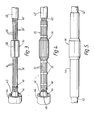
- a pre-shaped wraparound liner, 20, is shown in side elevation and plan view respectively.
- Elongate elements, 22, are shown as metal strips which are held together in a sheet array, 24, by a series of flexible strips of mylar, 26, bonded to the bridging elements, 22, by a pressure sensitive adhesive, 28.
- the liner, 20, has an intermediate region, 30, asymmetrically positioned with respect to a centerline, A, shaped to conform closely to a cable joint.
- Figures 2B and 2C are plan views of liners showing alternative positioning of the strips, 26, which as before, are sheets of adhesive backed Mylar.
- the strips or other means for holding the elements together may be positioned either exclusively on the end sections of the elongate elements ( Figure 2B) or exclusively in the intermediate section ( Figure 2C). However, the strips may cover all three regions, leaving uncovered the intermediate regions that are to extend over the change in diameter of the substrate.
- Figure 3 shows a joint, 32, in a three core power cable.
- the cores in the cables, 34, 34' have been jointed in the region, 36.
- insulating sheaths, 38, 38', armoring, 40, 40', and outer jackets 42, 42' were stripped back, and a heat-recoverable polymeric sleeve, 44, having a hot-melt adhesive layer, 46, on an inner surface was positioned over one cable end.
- Figure 4 shows a wraparound liner, 20, installed around a cable joint, 32.
- the bridging elements, 22, are then physically and electrically joined to the cable armoring, 40, 40', by means of hose clamps, 48, only one of which is shown in the drawing.
- Figure 5 shows the finished joint case after a polymeric sleeve, 44, has been positioned over the joint region, 36, and recovered into contact with the cable jackets, 42, 42', to form an environmental seal.
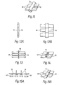
- Figure 6 is a side elevation of wraparound liner formed from a slotted sheet, 62.
- Figure 7 a plan view of the same liner as Figure 6, elongate elements, 64, are shown as having interconnecting portions, 66, therebetween. Two interconnecting portions, 66, join each pair of adjacent elements, 64, but the elements are not joined together at the far left and right hand sides as drawn, thus allowing the liner to conform to a substrate in the way required.
- the broken transverse lines indicate the portions of the liner that extend over the radial transitions of the substrate.
- Figures 8 through 15A and B show in partial views (except for the full view of 10B), alternative means for holding the elements, 68, in a sheet array.
- a plurality of malleable solder dots, 70 have been employed to connect adjacent metal elements, 68.
- a pair of strands of yarn, 72 have been woven around the elements, 68.
- FIG 10A a flexible strip of material, 76, having a plurality of paired slits, 78, through which the elements, 68, may be threaded thereby holding the elements in the desired sheet array, is shown in plan view.
- Figure 10B shows in plan view, a pair of such flexible strips, 76, after the elements, 68, have been threaded therethrough. Again, the broken transverse lines indicate the portions of the liner that extend over the radial transitions of the substrate.
- Figure 11 shows in partial plan view a flexible tube of material, 80, having a plurality of lateral apertures, 82, through which the elements, 68, may be press-fitted.
- a flexible strip of material, 84 having a plurality of lateral apertures, 86, through which the elements, 68, may be press-fitted is shown in a partial side view.
- Figure 12B shows in a partial plan view, the flexible strip, 84, after the elements, 68, have been inserted therethrough.
- Figures 13 through 15A and B the elements, 68, have been perforated to allow lacing, sewing, etc. therethrough.
- Figure 13 shows a pair of strands of yarn, 88, laced or sewn through perforations, 90.
- Elements, 68 may be linked by a hook, 92, as shown in
- FIG 14 a strip, 94, is shown having spaced protuberances, 96, molded integrally on one of its surfaces, which can be press-fitted into perforations, 90, by applying pressure at points B.
- the strip connector, 94 is shown after installation.
Landscapes
- Cable Accessories (AREA)
- Ropes Or Cables (AREA)
- Cosmetics (AREA)
- Non-Insulated Conductors (AREA)
- Measurement And Recording Of Electrical Phenomena And Electrical Characteristics Of The Living Body (AREA)
- Extrusion Moulding Of Plastics Or The Like (AREA)
- Mechanical Coupling Of Light Guides (AREA)
- Electroluminescent Light Sources (AREA)
- Laying Of Electric Cables Or Lines Outside (AREA)
Priority Applications (1)
| Application Number | Priority Date | Filing Date | Title |
|---|---|---|---|
| AT83302491T ATE40242T1 (de) | 1982-05-03 | 1983-05-03 | Kabelverbindungsschutz. |
Applications Claiming Priority (2)
| Application Number | Priority Date | Filing Date | Title |
|---|---|---|---|
| US06/374,558 US4533788A (en) | 1982-05-03 | 1982-05-03 | Assembly and method for cable joint protection |
| US374558 | 1982-05-03 |
Publications (3)
| Publication Number | Publication Date |
|---|---|
| EP0093617A2 true EP0093617A2 (fr) | 1983-11-09 |
| EP0093617A3 EP0093617A3 (en) | 1984-07-25 |
| EP0093617B1 EP0093617B1 (fr) | 1989-01-18 |
Family
ID=23477361
Family Applications (1)
| Application Number | Title | Priority Date | Filing Date |
|---|---|---|---|
| EP83302491A Expired EP0093617B1 (fr) | 1982-05-03 | 1983-05-03 | Protection de jonction de câble |
Country Status (12)
| Country | Link |
|---|---|
| US (1) | US4533788A (fr) |
| EP (1) | EP0093617B1 (fr) |
| JP (1) | JPS58207812A (fr) |
| AT (1) | ATE40242T1 (fr) |
| AU (1) | AU569999B2 (fr) |
| BR (1) | BR8302261A (fr) |
| CA (1) | CA1209655A (fr) |
| DE (1) | DE3379014D1 (fr) |
| FI (1) | FI79426C (fr) |
| GB (1) | GB2119586B (fr) |
| NO (1) | NO161830C (fr) |
| ZA (1) | ZA833103B (fr) |
Cited By (4)
| Publication number | Priority date | Publication date | Assignee | Title |
|---|---|---|---|---|
| FR2557389A1 (fr) * | 1983-12-21 | 1985-06-28 | Kabelmetal Electro Gmbh | Barrage pour l'eau transversale dans la zone du manchon d'un cable electrique a haute tension |
| GB2221356A (en) * | 1988-05-24 | 1990-01-31 | Raychem Ltd | Protecting cable splice |
| WO2001015295A1 (fr) * | 1999-08-24 | 2001-03-01 | Tyco Electronics Raychem Nv | Dispositif destine a entourer un substrat allonge |
| WO2021004612A1 (fr) * | 2019-07-05 | 2021-01-14 | British Telecommunications Public Limited Company | Appareil de protection |
Families Citing this family (15)
| Publication number | Priority date | Publication date | Assignee | Title |
|---|---|---|---|---|
| US4647718A (en) * | 1982-05-03 | 1987-03-03 | Raychem Corporation | Assembly and method for cable joint protection |
| GB8425761D0 (en) * | 1984-10-11 | 1984-11-14 | Raychem Sa Nv | Remote measurement of conditions |
| US4647713A (en) * | 1984-10-25 | 1987-03-03 | Nijs Jacob De | Pressurized telecommunication cable joint closure method and apparatus |
| JPS6241328U (fr) * | 1985-08-29 | 1987-03-12 | ||
| DE3602150A1 (de) * | 1986-01-24 | 1987-07-30 | Minnesota Mining & Mfg | Elektrische mittelspannungs-kabelverbindung, insbesondere fuer oelgefuellte papierisolierte kabel |
| JPS63109911U (fr) * | 1987-01-09 | 1988-07-15 | ||
| CA2001672E (fr) * | 1989-10-27 | 1997-04-29 | Journeymen Technologies Ltd | Appareil et méthode pour supporter une épissure (de câble) dans une boîte d'épissage |
| US5767442A (en) * | 1995-12-22 | 1998-06-16 | Amphenol Corporation | Non-skew cable assembly and method of making the same |
| JP2879011B2 (ja) * | 1996-05-08 | 1999-04-05 | トーマス アンド ベッツ コーポレーション | 電気ケーブルの細長いスプライス部を密封する方法と装置 |
| US6140572A (en) * | 1999-05-26 | 2000-10-31 | Abb Power T&D Company Inc. | Transformer tank with detachable cabinet interface |
| EP1277263B1 (fr) * | 2000-04-25 | 2006-06-28 | Prysmian Cavi e Sistemi Energia S.r.l. | Procede pour proteger les joints pour cables electriques, revetements de protection pour ces joints et joints ainsi proteges |
| MY129253A (en) * | 2000-04-25 | 2007-03-30 | Prysmian Cavi E Sistemi En Srl | "method for protecting joints for electrical cables, protective coating for said joints and joints thus protected" |
| CN103228973A (zh) | 2010-09-30 | 2013-07-31 | 费德罗-莫格尔动力系公司 | 带有其中具有阻隔件的针织阻隔延伸部的针织套筒及其构造方法 |
| US9543747B2 (en) * | 2013-10-30 | 2017-01-10 | Delphi Technologies, Inc. | Method for splicing shielded wire cables |
| CA2964466C (fr) * | 2014-10-16 | 2021-11-16 | Quanta Associates, L.P. | Procede et appareil de support d'une epissure permanente de cables pendant l'installation de cables |
Family Cites Families (23)
| Publication number | Priority date | Publication date | Assignee | Title |
|---|---|---|---|---|
| US2027962A (en) * | 1933-03-03 | 1936-01-14 | Nat Carbon Co Inc | Production of articles from plastic compositions |
| NL130678C (fr) * | 1960-07-15 | 1900-01-01 | ||
| US3297819A (en) * | 1964-08-10 | 1967-01-10 | Raychem Corp | Heat unstable covering |
| US3455336A (en) * | 1965-11-03 | 1969-07-15 | Raychem Corp | Heat recoverable article and process |
| US3717717A (en) * | 1970-04-20 | 1973-02-20 | Joslyn Mfg & Supply Co | Shrinkable cable joint sleeve, cable joint employing the same, and method of forming a cable joint |
| GB1431167A (en) * | 1972-09-08 | 1976-04-07 | Raychem Sa Nv | Assembly and method for protecitng and insulating a concuit junction |
| JPS558207B2 (fr) * | 1972-11-22 | 1980-03-03 | ||
| US4142592A (en) * | 1973-05-25 | 1979-03-06 | N.V. Raychem S.A. | Repairable assembly for protecting a cable junction and method of assembling same |
| GB1497051A (en) * | 1974-01-23 | 1978-01-05 | Raychem Sa Nv | Reinforced heat-recoverable articles and their uses |
| US3909500A (en) * | 1974-05-30 | 1975-09-30 | Westinghouse Electric Corp | Electrically shielded cable seal assembly and penetration combination |
| US4135553A (en) * | 1975-06-16 | 1979-01-23 | Raychem Corporation | Recoverable sleeve |
| US4039745A (en) * | 1976-01-16 | 1977-08-02 | The Okonite Company | Splices for high pressure pipe-type cables |
| JPS52119684A (en) * | 1976-03-05 | 1977-10-07 | Raychem Corp | Method of jointing of end portions of sheets consisted of heat recoverable material |
| DE2703406C3 (de) * | 1977-01-27 | 1981-10-29 | Siemens AG, 1000 Berlin und 8000 München | Verbindugnsanordnung für koaxiale Leitungen |
| JPS53108170A (en) * | 1977-03-04 | 1978-09-20 | Furukawa Electric Co Ltd:The | Method of shrinking heat-shrinkable sleeve by heating |
| US4164621A (en) * | 1977-08-08 | 1979-08-14 | Amerace Corporation | Cable shield connecting device |
| DE2807154C3 (de) * | 1978-02-20 | 1985-08-01 | Walter Rose Gmbh & Co Kg, 5800 Hagen | Kabelmuffe |
| CA1133997A (fr) * | 1978-02-21 | 1982-10-19 | N V Raychem Sa | Article thermoretrecissable a ceinture de retenue |
| US4179320A (en) * | 1978-04-10 | 1979-12-18 | Raychem Corporation | Recoverable articles |
| DE7930401U1 (de) * | 1979-09-11 | 1980-03-13 | N.V. Raychem S.A., Kessel-Lo (Belgien) | Kabelmuffeneinlage |
| US4282397A (en) * | 1979-11-05 | 1981-08-04 | Raychem Corporation | Wraparound splice case |
| GB2069773B (en) * | 1980-02-08 | 1984-02-08 | Raychem Sa Nv | Recoverable closure assembly |
| EP0050009B1 (fr) * | 1980-10-09 | 1985-05-22 | N.V. Raychem S.A. | Elément de raccordement composite |
-
1982
- 1982-05-03 US US06/374,558 patent/US4533788A/en not_active Expired - Lifetime
-
1983
- 1983-05-02 NO NO831544A patent/NO161830C/no unknown
- 1983-05-02 ZA ZA833103A patent/ZA833103B/xx unknown
- 1983-05-02 BR BR8302261A patent/BR8302261A/pt unknown
- 1983-05-02 FI FI831494A patent/FI79426C/fi not_active IP Right Cessation
- 1983-05-02 CA CA000427161A patent/CA1209655A/fr not_active Expired
- 1983-05-03 AU AU14169/83A patent/AU569999B2/en not_active Ceased
- 1983-05-03 GB GB08311978A patent/GB2119586B/en not_active Expired
- 1983-05-03 AT AT83302491T patent/ATE40242T1/de not_active IP Right Cessation
- 1983-05-03 DE DE8383302491T patent/DE3379014D1/de not_active Expired
- 1983-05-03 EP EP83302491A patent/EP0093617B1/fr not_active Expired
- 1983-05-04 JP JP58078891A patent/JPS58207812A/ja active Pending
Cited By (4)
| Publication number | Priority date | Publication date | Assignee | Title |
|---|---|---|---|---|
| FR2557389A1 (fr) * | 1983-12-21 | 1985-06-28 | Kabelmetal Electro Gmbh | Barrage pour l'eau transversale dans la zone du manchon d'un cable electrique a haute tension |
| GB2221356A (en) * | 1988-05-24 | 1990-01-31 | Raychem Ltd | Protecting cable splice |
| WO2001015295A1 (fr) * | 1999-08-24 | 2001-03-01 | Tyco Electronics Raychem Nv | Dispositif destine a entourer un substrat allonge |
| WO2021004612A1 (fr) * | 2019-07-05 | 2021-01-14 | British Telecommunications Public Limited Company | Appareil de protection |
Also Published As
| Publication number | Publication date |
|---|---|
| CA1209655A (fr) | 1986-08-12 |
| JPS58207812A (ja) | 1983-12-03 |
| NO161830B (no) | 1989-06-19 |
| EP0093617A3 (en) | 1984-07-25 |
| NO831544L (no) | 1983-11-04 |
| FI79426B (fi) | 1989-08-31 |
| NO161830C (no) | 1989-09-27 |
| US4533788A (en) | 1985-08-06 |
| EP0093617B1 (fr) | 1989-01-18 |
| FI831494L (fi) | 1983-11-04 |
| GB2119586A (en) | 1983-11-16 |
| DE3379014D1 (en) | 1989-02-23 |
| ZA833103B (en) | 1984-01-25 |
| GB8311978D0 (en) | 1983-06-08 |
| FI831494A0 (fi) | 1983-05-02 |
| AU569999B2 (en) | 1988-03-03 |
| GB2119586B (en) | 1986-02-12 |
| FI79426C (fi) | 1989-12-11 |
| BR8302261A (pt) | 1984-01-03 |
| ATE40242T1 (de) | 1989-02-15 |
| AU1416983A (en) | 1983-11-10 |
Similar Documents
| Publication | Publication Date | Title |
|---|---|---|
| US4533788A (en) | Assembly and method for cable joint protection | |
| US4289553A (en) | Heat-shrinkable article | |
| US4298415A (en) | Branch-off method | |
| US3691505A (en) | Heater cable splice and method of forming | |
| US4421945A (en) | Junction assembly | |
| CA1069192A (fr) | Article d'emballage scellable a la chaleur et methode de scellement connexe | |
| CN102356528B (zh) | 被覆电缆组件以及用于形成被覆电缆组件的方法和系统 | |
| EP0158519B1 (fr) | Objet à reprise thermique | |
| US4485269A (en) | Cable sealing | |
| EP0127457B1 (fr) | Objet électriquement thermorétractable | |
| GB1604984A (en) | Branchoff method | |
| US4518819A (en) | Clamp assembly for power cables | |
| EP0136154A2 (fr) | Jonctions et terminaisons de câbles | |
| US10283878B2 (en) | Neutral conductor connection protection devices and cover assembly kits, electrical connections and methods including same | |
| US4647718A (en) | Assembly and method for cable joint protection | |
| US5451278A (en) | Environmental protection | |
| GB1603626A (en) | Junction assembly | |
| CA1197580A (fr) | Raccord etanche a l'eau pour cables electriques | |
| GB2254739A (en) | Cable joint | |
| EP0120603B1 (fr) | Branchement de câble et méthod de la former | |
| WO1998021796A1 (fr) | Systemes et procedes pour obturation etanche avec noyau de support | |
| WO1998021797A1 (fr) | Elements d'insertion pour liaison d'obturations etanches | |
| WO1998021798A1 (fr) | Systemes et procedes pour obturation etanche par adhesion | |
| GB2284110A (en) | Sealing of cable crutch | |
| CA1156817A (fr) | Raccord a pince de branchement enveloppante et isolante |
Legal Events
| Date | Code | Title | Description |
|---|---|---|---|
| PUAI | Public reference made under article 153(3) epc to a published international application that has entered the european phase |
Free format text: ORIGINAL CODE: 0009012 |
|
| 17P | Request for examination filed |
Effective date: 19830525 |
|
| AK | Designated contracting states |
Designated state(s): AT BE CH DE FR IT LI NL SE |
|
| PUAL | Search report despatched |
Free format text: ORIGINAL CODE: 0009013 |
|
| AK | Designated contracting states |
Designated state(s): AT BE CH DE FR IT LI NL SE |
|
| RAP1 | Party data changed (applicant data changed or rights of an application transferred) |
Owner name: RAYCHEM CORPORATION (A DELAWARE CORPORATION) |
|
| GRAA | (expected) grant |
Free format text: ORIGINAL CODE: 0009210 |
|
| AK | Designated contracting states |
Kind code of ref document: B1 Designated state(s): AT BE CH DE FR IT LI NL SE |
|
| PG25 | Lapsed in a contracting state [announced via postgrant information from national office to epo] |
Ref country code: NL Effective date: 19890118 Ref country code: BE Effective date: 19890118 Ref country code: AT Effective date: 19890118 |
|
| REF | Corresponds to: |
Ref document number: 40242 Country of ref document: AT Date of ref document: 19890215 Kind code of ref document: T |
|
| REF | Corresponds to: |
Ref document number: 3379014 Country of ref document: DE Date of ref document: 19890223 |
|
| ITF | It: translation for a ep patent filed | ||
| ET | Fr: translation filed | ||
| NLV1 | Nl: lapsed or annulled due to failure to fulfill the requirements of art. 29p and 29m of the patents act | ||
| PLBE | No opposition filed within time limit |
Free format text: ORIGINAL CODE: 0009261 |
|
| 26N | No opposition filed | ||
| ITTA | It: last paid annual fee | ||
| EAL | Se: european patent in force in sweden |
Ref document number: 83302491.2 |
|
| PGFP | Annual fee paid to national office [announced via postgrant information from national office to epo] |
Ref country code: SE Payment date: 19980515 Year of fee payment: 16 |
|
| PGFP | Annual fee paid to national office [announced via postgrant information from national office to epo] |
Ref country code: CH Payment date: 19980526 Year of fee payment: 16 |
|
| PG25 | Lapsed in a contracting state [announced via postgrant information from national office to epo] |
Ref country code: SE Free format text: LAPSE BECAUSE OF NON-PAYMENT OF DUE FEES Effective date: 19990504 |
|
| PG25 | Lapsed in a contracting state [announced via postgrant information from national office to epo] |
Ref country code: LI Free format text: LAPSE BECAUSE OF NON-PAYMENT OF DUE FEES Effective date: 19990531 Ref country code: CH Free format text: LAPSE BECAUSE OF NON-PAYMENT OF DUE FEES Effective date: 19990531 |
|
| REG | Reference to a national code |
Ref country code: CH Ref legal event code: PL |
|
| EUG | Se: european patent has lapsed |
Ref document number: 83302491.2 |
|
| PGFP | Annual fee paid to national office [announced via postgrant information from national office to epo] |
Ref country code: DE Payment date: 20010423 Year of fee payment: 19 |
|
| PGFP | Annual fee paid to national office [announced via postgrant information from national office to epo] |
Ref country code: FR Payment date: 20010518 Year of fee payment: 19 |
|
| PG25 | Lapsed in a contracting state [announced via postgrant information from national office to epo] |
Ref country code: DE Free format text: LAPSE BECAUSE OF NON-PAYMENT OF DUE FEES Effective date: 20021203 |
|
| PG25 | Lapsed in a contracting state [announced via postgrant information from national office to epo] |
Ref country code: FR Free format text: LAPSE BECAUSE OF NON-PAYMENT OF DUE FEES Effective date: 20030131 |
|
| REG | Reference to a national code |
Ref country code: FR Ref legal event code: ST |