EP0093631A1 - Sicherheitsanschlag für die Zapfen von drehregelbaren Leitschaufeln - Google Patents
Sicherheitsanschlag für die Zapfen von drehregelbaren Leitschaufeln Download PDFInfo
- Publication number
- EP0093631A1 EP0093631A1 EP83400695A EP83400695A EP0093631A1 EP 0093631 A1 EP0093631 A1 EP 0093631A1 EP 83400695 A EP83400695 A EP 83400695A EP 83400695 A EP83400695 A EP 83400695A EP 0093631 A1 EP0093631 A1 EP 0093631A1
- Authority
- EP
- European Patent Office
- Prior art keywords
- pivot
- arm
- inner ring
- fixing means
- foot pivot
- Prior art date
- Legal status (The legal status is an assumption and is not a legal conclusion. Google has not performed a legal analysis and makes no representation as to the accuracy of the status listed.)
- Granted
Links
- 229910003460 diamond Inorganic materials 0.000 claims description 2
- 239000010432 diamond Substances 0.000 claims description 2
- 230000006835 compression Effects 0.000 description 4
- 238000007906 compression Methods 0.000 description 4
- 230000006378 damage Effects 0.000 description 4
- 238000005086 pumping Methods 0.000 description 3
- 238000005452 bending Methods 0.000 description 1
- 229940082150 encore Drugs 0.000 description 1
- 239000000463 material Substances 0.000 description 1
Images

Classifications
-
- F—MECHANICAL ENGINEERING; LIGHTING; HEATING; WEAPONS; BLASTING
- F01—MACHINES OR ENGINES IN GENERAL; ENGINE PLANTS IN GENERAL; STEAM ENGINES
- F01D—NON-POSITIVE DISPLACEMENT MACHINES OR ENGINES, e.g. STEAM TURBINES
- F01D17/00—Regulating or controlling by varying flow
- F01D17/10—Final actuators
- F01D17/12—Final actuators arranged in stator parts
- F01D17/14—Final actuators arranged in stator parts varying effective cross-sectional area of nozzles or guide conduits
- F01D17/16—Final actuators arranged in stator parts varying effective cross-sectional area of nozzles or guide conduits by means of nozzle vanes
- F01D17/162—Final actuators arranged in stator parts varying effective cross-sectional area of nozzles or guide conduits by means of nozzle vanes for axial flow, i.e. the vanes turning around axes which are essentially perpendicular to the rotor centre line
Definitions
- the invention relates to a safety stop device for a stator vane pivot with variable setting, the vane comprising a head pivot and a foot pivot, the head pivot, cooperating with a bearing fixed in the motor housing. , being driven by a device for adjusting the orientation of the blades, the foot pivot being movable in a bearing fixed in an inner ring of the motor.
- stator vanes with variable setting is given in French patent 2 205 952 in which the preliminary compression stage and four upper compression stages are fitted with adjustable stator fins.
- the pivots at the head of these fins are controlled by a ring and lever system which, from a single order, changes the orientation of the fins of each stage concerned.
- the stator of the preliminary compression stage comprises fins of relatively large dimensions, which are further provided with a pivot at the foot allowing the bending forces to be taken up.
- the invention aims to minimize the drawbacks resulting from a break in control and is suitable in particular for stator blades with variable setting controlled at the head and comprising a foot pivot.
- the device according to the invention is remarkable in that it consists of an arm comprising means for fixing to the foot pivot and abutment elements provided in the inner ring against which the arm bears.
- FIG. 1 shows in partial section part of a compressor stage comprising a stator 1 formed of a crown of blades 2 with pivots at the head 3 and at the foot 4, the orientation of which is controlled at the head by a control system 5 located outside the crankcase 6, and a rotor 7 formed of vanes 8, the feet of which are embedded in the rotor disc 9.
- the head pivot 3 pivots in a bearing fixed in the upper ring or casing 6.
- a connecting rod or control lever 10 is fixed by one of its ends to the pivot 3 and, by its other end, to a control device 11 of the crown of blades.
- the foot pivot 4 is held in a staircase 12 fixed in the inner ring (13).
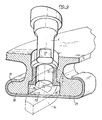
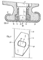
- the stop device according to the invention (FIGS. 2, 3, 5) consists of at least one arm 14 comprising means for fixing to the pivot 4 and stop elements 15, 16 fixed to the inner ring 13 and against which the arm 14 is supported, in the event of a break in the control mechanism 10-11 for example.
- the cylindrical pivot 4 of the blade root carries at its end at least one flat 17, and preferably two parallel flat.
- the pivot 4 cooperates with a bearing 12 consisting of a bush made of a self-lubricating material fixed in the lower ring 13 of the stage.
- This ring is provided on its inner surface 18 with a circumferential groove 19 in which the end of the pivot 4 projects and, in particular, the part carrying the flats 17.
- An arm 14 is fixed on the end of the pivot by fixing means formed by a central hole 20 of rectangular shape with two opposite curved sides corresponding to the shape of the end of the pivot.
- the arm 14 has, in plan view ( Figure 4) a diamond shape in which the two vertices 22, 23 located on the small diagonal, are rounded. The length of this diagonal is less than the width of the groove 19.
- angles of the rhombus are determined so as to allow the orientation of the blades to be adjusted at a given angle.
- the end of the opposite sides of the rhombus is placed against the abutment elements formed by the sides 15, 16 of the groove 19.
- annular profile 21 for example in the form of a C, is fixed by any means known per se to the lower ring 13.
- the foot pivot 4 carries in its axis a hexagonal blind hole 24, into which penetrates a stud 25 of comparable shape and dimensions, perpendicular to the plane of the arm 14 and integral with that -this.
- a profile annular in C 21 fixed on the inner ring seals and possibly maintains the arm in cooperation with the pivot.
- the fact of limiting the amplitude of the possible accidental movement of the blade makes it possible to limit the total length of the motor: in fact, the blades can no longer be placed in a flag, rope parallel to the wind bed, we can reduce the length of the motor by 5 mm per stage, resulting in a significant reduction in mass.
Landscapes
- Engineering & Computer Science (AREA)
- Mechanical Engineering (AREA)
- General Engineering & Computer Science (AREA)
- Structures Of Non-Positive Displacement Pumps (AREA)
- Sliding-Contact Bearings (AREA)
- Control Of Turbines (AREA)
Applications Claiming Priority (2)
| Application Number | Priority Date | Filing Date | Title |
|---|---|---|---|
| FR8206117A FR2524934B1 (fr) | 1982-04-08 | 1982-04-08 | Dispositif de butee de securite pour pivot d'aubes de stator a calage variable |
| FR8206117 | 1982-04-08 |
Publications (2)
| Publication Number | Publication Date |
|---|---|
| EP0093631A1 true EP0093631A1 (de) | 1983-11-09 |
| EP0093631B1 EP0093631B1 (de) | 1986-01-29 |
Family
ID=9272876
Family Applications (1)
| Application Number | Title | Priority Date | Filing Date |
|---|---|---|---|
| EP83400695A Expired EP0093631B1 (de) | 1982-04-08 | 1983-04-06 | Sicherheitsanschlag für die Zapfen von drehregelbaren Leitschaufeln |
Country Status (5)
| Country | Link |
|---|---|
| US (1) | US4514141A (de) |
| EP (1) | EP0093631B1 (de) |
| JP (1) | JPS58206810A (de) |
| DE (1) | DE3361967D1 (de) |
| FR (1) | FR2524934B1 (de) |
Cited By (2)
| Publication number | Priority date | Publication date | Assignee | Title |
|---|---|---|---|---|
| FR2556410A1 (fr) * | 1983-12-07 | 1985-06-14 | Snecma | Dispositif de centrage de l'anneau interieur d'un stator a ailettes a calage variable |
| FR2582720A1 (fr) * | 1985-05-29 | 1986-12-05 | Snecma | Procede de realisation de pivot d'aube de turbomachine et aube de stator le comportant |
Families Citing this family (39)
| Publication number | Priority date | Publication date | Assignee | Title |
|---|---|---|---|---|
| FR2583817B1 (fr) * | 1985-06-20 | 1988-07-29 | Snecma | Biellette de commande d'aube a calage variable de stator de compresseur de turbomachine |
| US4695220A (en) * | 1985-09-13 | 1987-09-22 | General Electric Company | Actuator for variable vanes |
| US4792277A (en) * | 1987-07-08 | 1988-12-20 | United Technologies Corporation | Split shroud compressor |
| FR2644525B1 (fr) * | 1989-03-15 | 1991-05-24 | Snecma | Systeme de retention d'aubes de stator a calage variable |
| US5492446A (en) * | 1994-12-15 | 1996-02-20 | General Electric Company | Self-aligning variable stator vane |
| FR2742799B1 (fr) * | 1995-12-20 | 1998-01-16 | Snecma | Palier d'extremite interne d'aube pivotante |
| US20080053547A1 (en) * | 1997-11-24 | 2008-03-06 | Yungrwei Chen | Energy attenuation apparatus for a conduit conveying liquid under pressure, system incorporating same, and method of attenuating energy in a conduit |
| US6019574A (en) * | 1998-08-13 | 2000-02-01 | General Electric Company | Mismatch proof variable stator vane |
| US6413043B1 (en) * | 2000-11-09 | 2002-07-02 | General Electric Company | Inlet guide vane and shroud support contact |
| EP1205639A1 (de) * | 2000-11-09 | 2002-05-15 | General Electric Company | Befestigungsanordnung von verstellbaren Turbinenleitschaufeln im inneren Haltering |
| US6682299B2 (en) | 2001-11-15 | 2004-01-27 | General Electric Company | Variable stator vane support arrangement |
| DE10161292A1 (de) * | 2001-12-13 | 2003-06-26 | Rolls Royce Deutschland | Lagerring zur Lagerung von Schaufelfüßen von verstellbaren Statorschaufeln im Hochdruckverdichter einer Gasturbine |
| FR2835562B1 (fr) * | 2002-02-07 | 2004-07-16 | Snecma Moteurs | Agencement de pivotement d'aube de stator dans une turbomachine |
| GB2412947B (en) * | 2004-04-07 | 2006-06-14 | Rolls Royce Plc | Variable stator vane assemblies |
| FR2875270B1 (fr) * | 2004-09-10 | 2006-12-01 | Snecma Moteurs Sa | Retenue des clavettes de centrage des anneaux sous aubes de stator a calage variable d'un moteur a turbine a gaz |
| GB0504588D0 (en) * | 2005-03-05 | 2005-04-13 | Rolls Royce Plc | Pivot ring |
| US7249613B1 (en) | 2006-02-03 | 2007-07-31 | Dayco Products, Llc | Energy attenuation device |
| US7717135B2 (en) * | 2006-02-03 | 2010-05-18 | Yh America, Inc. | Energy attenuation device |
| DE102006024085B4 (de) * | 2006-05-23 | 2020-04-16 | MTU Aero Engines AG | Turboverdichter in Axialbauweise |
| US20080210486A1 (en) * | 2007-03-02 | 2008-09-04 | Dayco Products, Llc | Energy attenuation device |
| FR2928961B1 (fr) * | 2008-03-19 | 2015-11-13 | Snecma | Distributeur sectorise pour une turbomachine. |
| FR2964710B1 (fr) * | 2010-09-14 | 2012-08-31 | Snecma | Douille pour aube a calage variable |
| FR2995934B1 (fr) * | 2012-09-24 | 2018-06-01 | Safran Aircraft Engines | Aube pour redresseur de turbomachine |
| US9995166B2 (en) * | 2014-11-21 | 2018-06-12 | General Electric Company | Turbomachine including a vane and method of assembling such turbomachine |
| DE102014223975A1 (de) * | 2014-11-25 | 2016-05-25 | MTU Aero Engines AG | Leitschaufelkranz und Strömungsmaschine |
| JP6694950B2 (ja) * | 2016-03-30 | 2020-05-20 | 三菱重工エンジン&ターボチャージャ株式会社 | 可変容量型ターボチャージャ |
| FR3053383B1 (fr) * | 2016-07-04 | 2019-08-02 | Safran Aircraft Engines | Clinquant de retention de douilles d'anneaux de commande d'aubes a calage variable et turboreacteur l'incorporant |
| FR3055374B1 (fr) * | 2016-08-23 | 2018-08-03 | Safran Aircraft Engines | Piece d'interface pour reconditionner un anneau de commande d'un compresseur de moteur, et procede de reconditionnement associe |
| DE102016215807A1 (de) * | 2016-08-23 | 2018-03-01 | MTU Aero Engines AG | Innenring für einen Leitschaufelkranz einer Strömungsmaschine |
| DE102017109952A1 (de) * | 2017-05-09 | 2018-11-15 | Rolls-Royce Deutschland Ltd & Co Kg | Rotorvorrichtung einer Strömungsmaschine |
| GB201715165D0 (en) | 2017-09-20 | 2017-11-01 | Rolls Royce Plc | Bearing assembly |
| DE102018210601A1 (de) * | 2018-06-28 | 2020-01-02 | MTU Aero Engines AG | Segmentring zur montage in einer strömungsmaschine |
| DE102018213983A1 (de) | 2018-08-20 | 2020-02-20 | MTU Aero Engines AG | Verstellbare Leitschaufelanordnung, Leitschaufel, Dichtungsträger und Turbomaschine |
| CN112096658B (zh) * | 2020-11-06 | 2021-01-22 | 中国航发上海商用航空发动机制造有限责任公司 | 航空发动机压气机及其可调静子叶片位置保持结构 |
| FR3123885B1 (fr) * | 2021-06-15 | 2023-06-16 | Safran Aircraft Engines | Redresseur non carene de turbomachine equipe d’aubes de stator fixees a des pivots et turbomachine correspondante |
| FR3132123B1 (fr) * | 2022-01-21 | 2023-12-08 | Safran Aircraft Engines | Aube de redresseur de flux secondaire de turbomachine, turbomachine munie de celle-ci |
| US12180974B2 (en) | 2022-03-24 | 2024-12-31 | Copeland Lp | Variable inlet guide vane apparatus and compressor including same |
| US12516678B2 (en) * | 2023-03-20 | 2026-01-06 | Copeland Lp | Variable inlet guide vane apparatus combined with compressor end cap |
| FR3161923B1 (fr) * | 2024-05-06 | 2026-05-15 | Safran Aircraft Engines | Etage d’aubes a calage variable pour une turbomachine d’aeronef |
Citations (7)
| Publication number | Priority date | Publication date | Assignee | Title |
|---|---|---|---|---|
| BE556572A (de) * | 1955-08-16 | |||
| GB621175A (en) * | 1946-11-16 | 1949-04-05 | Power Jets Res & Dev Ltd | Improvements in or relating to stator blading of compressors and like machines |
| FR1041161A (fr) * | 1951-08-14 | 1953-10-21 | Napier & Son Ltd | Perfectionnements aux appareils à réaction à courant axial de fluide comprenant au moins une rangée d'aubes radiales |
| DE1047538B (de) * | 1956-10-29 | 1958-12-24 | Siemens Ag | Drehbare Leitschaufel mit begrenztem Drehbereich, insbesondere fuer Turbinen, z. B. Gasturbinen |
| US3029067A (en) * | 1956-05-31 | 1962-04-10 | Garrett Corp | Variable area nozzle means for turbines |
| US3303992A (en) * | 1965-03-03 | 1967-02-14 | Gen Motors Corp | Variable vane stator ring |
| US3367628A (en) * | 1966-10-31 | 1968-02-06 | United Aircraft Corp | Movable vane unit |
Family Cites Families (5)
| Publication number | Priority date | Publication date | Assignee | Title |
|---|---|---|---|---|
| US1570536A (en) * | 1925-02-20 | 1926-01-19 | Morgan Smith S Co | Gate stop for turbine construction |
| FR1281702A (fr) * | 1960-03-15 | 1962-01-12 | Daimler Benz Ag | Dispositif de palier d'aubes directrices réglables pour turbines à gaz ou pour turbines à air chaud |
| US3107546A (en) * | 1960-04-25 | 1963-10-22 | Pacific Valves Inc | Internal stop means for valves |
| NO119216B (de) * | 1965-04-12 | 1970-04-06 | Nydqvist & Holm Ab | |
| US3295827A (en) * | 1966-04-06 | 1967-01-03 | Gen Motors Corp | Variable configuration blade |
-
1982
- 1982-04-08 FR FR8206117A patent/FR2524934B1/fr not_active Expired
-
1983
- 1983-04-06 EP EP83400695A patent/EP0093631B1/de not_active Expired
- 1983-04-06 DE DE8383400695T patent/DE3361967D1/de not_active Expired
- 1983-04-07 US US06/482,940 patent/US4514141A/en not_active Expired - Fee Related
- 1983-04-07 JP JP58061493A patent/JPS58206810A/ja active Granted
Patent Citations (7)
| Publication number | Priority date | Publication date | Assignee | Title |
|---|---|---|---|---|
| GB621175A (en) * | 1946-11-16 | 1949-04-05 | Power Jets Res & Dev Ltd | Improvements in or relating to stator blading of compressors and like machines |
| FR1041161A (fr) * | 1951-08-14 | 1953-10-21 | Napier & Son Ltd | Perfectionnements aux appareils à réaction à courant axial de fluide comprenant au moins une rangée d'aubes radiales |
| BE556572A (de) * | 1955-08-16 | |||
| US3029067A (en) * | 1956-05-31 | 1962-04-10 | Garrett Corp | Variable area nozzle means for turbines |
| DE1047538B (de) * | 1956-10-29 | 1958-12-24 | Siemens Ag | Drehbare Leitschaufel mit begrenztem Drehbereich, insbesondere fuer Turbinen, z. B. Gasturbinen |
| US3303992A (en) * | 1965-03-03 | 1967-02-14 | Gen Motors Corp | Variable vane stator ring |
| US3367628A (en) * | 1966-10-31 | 1968-02-06 | United Aircraft Corp | Movable vane unit |
Cited By (6)
| Publication number | Priority date | Publication date | Assignee | Title |
|---|---|---|---|---|
| FR2556410A1 (fr) * | 1983-12-07 | 1985-06-14 | Snecma | Dispositif de centrage de l'anneau interieur d'un stator a ailettes a calage variable |
| EP0146449A1 (de) * | 1983-12-07 | 1985-06-26 | Societe Nationale D'etude Et De Construction De Moteurs D'aviation, "S.N.E.C.M.A." | Einrichtung für die Zentrierung eines inneren Statorringes, unterstützt durch bewegliche Schaufeln |
| US4604030A (en) * | 1983-12-07 | 1986-08-05 | Societe Nationale D'etude Et De Construction De Moteurs D'aviation S.N.E.C.M.A. | Compressor with variable incidence stator vanes |
| FR2582720A1 (fr) * | 1985-05-29 | 1986-12-05 | Snecma | Procede de realisation de pivot d'aube de turbomachine et aube de stator le comportant |
| EP0204615A1 (de) * | 1985-05-29 | 1986-12-10 | Societe Nationale D'etude Et De Construction De Moteurs D'aviation, "S.N.E.C.M.A." | Herstellungsverfahren für eine Turbinenschaufel und für ihren Drehpunkt |
| US4706354A (en) * | 1985-05-29 | 1987-11-17 | Societe Nationale D'etude Et De Construction De Moteurs D'aviation "S.N.E.C.M.A." | Method of manufacturing a root pivot assembly of a variable incidence turbo-machine blade |
Also Published As
| Publication number | Publication date |
|---|---|
| EP0093631B1 (de) | 1986-01-29 |
| JPH029161B2 (de) | 1990-02-28 |
| FR2524934A1 (fr) | 1983-10-14 |
| DE3361967D1 (en) | 1986-03-13 |
| US4514141A (en) | 1985-04-30 |
| FR2524934B1 (fr) | 1986-12-26 |
| JPS58206810A (ja) | 1983-12-02 |
Similar Documents
| Publication | Publication Date | Title |
|---|---|---|
| EP0093631B1 (de) | Sicherheitsanschlag für die Zapfen von drehregelbaren Leitschaufeln | |
| EP1696134B1 (de) | Regeleinrichtung zur Zentrierung des Verstellringes für die verstellbaren Leitschaufeln einer Turbomaschine. | |
| AU1602583A (en) | Mattress | |
| EP2977829A1 (de) | Anordnung mit beweglichem Bremselement einer Uhr | |
| FR2582720A1 (fr) | Procede de realisation de pivot d'aube de turbomachine et aube de stator le comportant | |
| CH643633A5 (fr) | Roue a pales cooperant avec un fluide. | |
| EP0052534B1 (de) | Absperrklappe | |
| EP1696104B1 (de) | Betätigungseinrichtung für Leitgitter variabler Geometrie einer Turbomaschine | |
| FR2853930A1 (fr) | Dispositif de commande d'aubes a calage variable dans une turbomachine | |
| EP0209428B1 (de) | Verstellhebel für eine Statorschaufel | |
| FR2609506A1 (fr) | Turbine multi-usage | |
| FR2776307A1 (fr) | Mecanisme de tirage pour mecanique d'armure et metier a tisser comprenant un tel mecanisme de tirage | |
| EP2721293B1 (de) | Windturbine mit vertikaler achse mit bremsvorrichtung | |
| FR2863318A1 (fr) | Aerogenerateur a pales presentant un bord d'attaque deporte, et pale correspondante | |
| EP0155880A1 (de) | Vorrichtung zum Offenhalten einer sich drehender Tür o.dgl. | |
| FR2963175A1 (fr) | Rotor pour moteur synchrone | |
| FR2613266A1 (fr) | Outil de prehension et de vissage oriente d'une vis a etrier | |
| EP0143061A1 (de) | Automatische Verstellvorrichtung für den Propellerblattwinkel | |
| FR2877059A1 (fr) | Biellette de commande destinee a l'entrainement d'une aube a calage variable | |
| FR2897120A1 (fr) | Pivot d'aube a angle de calage variable de turbomachine et dispositif de commande d'une telle aube | |
| WO1990008615A1 (fr) | Dispositif pour degager un tronçon coupe a longueur sur une scie a moteur | |
| FR2876752A1 (fr) | Dispositif de pas variable pour eolienne a axe de rotation dans la direction du vent agissant par action combinee de la poussee du vent sur les pales et de regulateurs centrifuges | |
| EP0253694B1 (de) | Zündverteiler für Brennkraftmaschinen, besonders von Fahrzeugen | |
| EP0246944B1 (de) | Gasdruckverminderungsventil und Herstellungsverfahren | |
| FR2743846A1 (fr) | Douille de retenue d'aube pivotante et agencement correspondant |
Legal Events
| Date | Code | Title | Description |
|---|---|---|---|
| PUAI | Public reference made under article 153(3) epc to a published international application that has entered the european phase |
Free format text: ORIGINAL CODE: 0009012 |
|
| 17P | Request for examination filed |
Effective date: 19830418 |
|
| AK | Designated contracting states |
Designated state(s): DE FR GB |
|
| GRAA | (expected) grant |
Free format text: ORIGINAL CODE: 0009210 |
|
| AK | Designated contracting states |
Designated state(s): DE FR GB |
|
| REF | Corresponds to: |
Ref document number: 3361967 Country of ref document: DE Date of ref document: 19860313 |
|
| PLBE | No opposition filed within time limit |
Free format text: ORIGINAL CODE: 0009261 |
|
| STAA | Information on the status of an ep patent application or granted ep patent |
Free format text: STATUS: NO OPPOSITION FILED WITHIN TIME LIMIT |
|
| 26N | No opposition filed | ||
| REG | Reference to a national code |
Ref country code: FR Ref legal event code: CL |
|
| PGFP | Annual fee paid to national office [announced via postgrant information from national office to epo] |
Ref country code: FR Payment date: 19930324 Year of fee payment: 11 |
|
| PGFP | Annual fee paid to national office [announced via postgrant information from national office to epo] |
Ref country code: GB Payment date: 19930326 Year of fee payment: 11 |
|
| PGFP | Annual fee paid to national office [announced via postgrant information from national office to epo] |
Ref country code: DE Payment date: 19930630 Year of fee payment: 11 |
|
| PG25 | Lapsed in a contracting state [announced via postgrant information from national office to epo] |
Ref country code: GB Effective date: 19940406 |
|
| GBPC | Gb: european patent ceased through non-payment of renewal fee |
Effective date: 19940406 |
|
| PG25 | Lapsed in a contracting state [announced via postgrant information from national office to epo] |
Ref country code: FR Effective date: 19941229 |
|
| PG25 | Lapsed in a contracting state [announced via postgrant information from national office to epo] |
Ref country code: DE Effective date: 19950103 |
|
| REG | Reference to a national code |
Ref country code: FR Ref legal event code: ST |