EP0093685B1 - Verfahren zum Biegen von Profilstahl - Google Patents
Verfahren zum Biegen von Profilstahl Download PDFInfo
- Publication number
- EP0093685B1 EP0093685B1 EP19830630075 EP83630075A EP0093685B1 EP 0093685 B1 EP0093685 B1 EP 0093685B1 EP 19830630075 EP19830630075 EP 19830630075 EP 83630075 A EP83630075 A EP 83630075A EP 0093685 B1 EP0093685 B1 EP 0093685B1
- Authority
- EP
- European Patent Office
- Prior art keywords
- force
- bending
- web
- core
- wing
- Prior art date
- Legal status (The legal status is an assumption and is not a legal conclusion. Google has not performed a legal analysis and makes no representation as to the accuracy of the status listed.)
- Expired
Links
- 238000000034 method Methods 0.000 title claims description 23
- 238000005452 bending Methods 0.000 title claims description 20
- 229910000831 Steel Inorganic materials 0.000 title claims description 6
- 239000010959 steel Substances 0.000 title claims description 6
- 238000009434 installation Methods 0.000 description 4
- 230000006835 compression Effects 0.000 description 2
- 238000007906 compression Methods 0.000 description 2
- 238000010276 construction Methods 0.000 description 2
- 238000007796 conventional method Methods 0.000 description 2
- 238000010586 diagram Methods 0.000 description 1
- 230000003631 expected effect Effects 0.000 description 1
- 238000005096 rolling process Methods 0.000 description 1
- 230000002269 spontaneous effect Effects 0.000 description 1
Images

Classifications
-
- B—PERFORMING OPERATIONS; TRANSPORTING
- B21—MECHANICAL METAL-WORKING WITHOUT ESSENTIALLY REMOVING MATERIAL; PUNCHING METAL
- B21D—WORKING OR PROCESSING OF SHEET METAL OR METAL TUBES, RODS OR PROFILES WITHOUT ESSENTIALLY REMOVING MATERIAL; PUNCHING METAL
- B21D7/00—Bending rods, profiles, or tubes
- B21D7/06—Bending rods, profiles, or tubes in press brakes or between rams and anvils or abutments; Pliers with forming dies
Definitions
- the present invention relates to a method for bending steel beams. It has been known for a very long time that it is advantageous to produce steel beams which have a bend, with the aim of compensating for the bending of the beams under their own weight and that of the concrete slabs and of increasing their bearing force.
- the current method used to bend beams is to arrange the beam so that one of the wings touches two fixed and spaced stops and to exert on the other wing, at a point located in the middle between said stops sufficient to achieve the desired counter-jib.
- the beams currently used in heavy construction eg bridges
- the pressures exerted on the wings can be 400-500 t and the counter-arrows to be made can reach 200 mm.
- the object of the invention was to propose a bending method which eliminates the problems described. This object is achieved by the method according to the invention as characterized in the claims.
- force 30 is applied to the wing 2 which bears against the stops 40, 41 and the energy is transmitted through the core 3 to the wing 1 as traction and it can be seen in practice that this traction succeeds in straightening out deformations possibly present before bending.
- Fig. 4 shows the diagram of the installation according to the invention which comprises in particular two fixed stops 40, 41 which are spaced apart and two stops 10, 11 serving to impart force 30 to wing 2.
- Force 30 is created by a press not shown.
- the stops 10, 11 are applied to the wing 2; they have a profile such that contact with wing 1 is avoided.
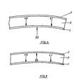
- Figs. 5 and 6 represent possible embodiments of the method; in both cases the forces created in the core 3 are only tensile forces.
- the pressure 30 acts on the wing 1 which delimits the minimum radius of the curved profile; the same applies to the back pressure 40, 41.
- a device must therefore be provided which has two stops 40, 41 each of which will have the form of the stops 10, 11 shown in fig. 4. It is understood that this device will be more complicated than that of FIG. 4.
- the embodiment shown in fig. 6 provides for the pressure 30 to be exerted on the wing 2, which delimits the maximum radius of the curved profile and the back pressure 40, 41 on the wing 1, which delimits the minimum radius of the curved profile.
- the counter-jib to be made was 175 mm.
Landscapes
- Engineering & Computer Science (AREA)
- Mechanical Engineering (AREA)
- Bending Of Plates, Rods, And Pipes (AREA)
Claims (4)
Applications Claiming Priority (4)
| Application Number | Priority Date | Filing Date | Title |
|---|---|---|---|
| LU84126 | 1982-05-04 | ||
| LU84126A LU84126A1 (fr) | 1982-05-04 | 1982-05-04 | Procede pour le cintrage de profiles en acier |
| LU84289A LU84289A1 (fr) | 1982-07-23 | 1982-07-23 | Procede pour le cintrage de profiles en acier |
| LU84289 | 1982-07-23 |
Publications (2)
| Publication Number | Publication Date |
|---|---|
| EP0093685A1 EP0093685A1 (de) | 1983-11-09 |
| EP0093685B1 true EP0093685B1 (de) | 1986-09-10 |
Family
ID=26640289
Family Applications (1)
| Application Number | Title | Priority Date | Filing Date |
|---|---|---|---|
| EP19830630075 Expired EP0093685B1 (de) | 1982-05-04 | 1983-04-29 | Verfahren zum Biegen von Profilstahl |
Country Status (2)
| Country | Link |
|---|---|
| EP (1) | EP0093685B1 (de) |
| DE (1) | DE3365992D1 (de) |
Families Citing this family (1)
| Publication number | Priority date | Publication date | Assignee | Title |
|---|---|---|---|---|
| RU2492015C1 (ru) * | 2011-12-28 | 2013-09-10 | Российская Федерация, от имени которой выступает Министерство промышленности и торговли РФ (МИНПРОМТОРГ РОССИИ) | Способ изготовления шпангоута |
Family Cites Families (5)
| Publication number | Priority date | Publication date | Assignee | Title |
|---|---|---|---|---|
| DE1335539U (de) * | ||||
| US1351472A (en) * | 1919-09-12 | 1920-08-31 | James E Conway | Bending-machine |
| US1890949A (en) * | 1931-05-07 | 1932-12-13 | Commercial Shearing | Method and apparatus for bending |
| DE920703C (de) * | 1944-03-18 | 1954-11-29 | Dortmunder Union Brueckenbau A | Vorrichtung zum Kaltbiegen flacher Konstruktionsteile, insbesondere Wulsteisen |
| US3017915A (en) * | 1956-04-30 | 1962-01-23 | Bethlehem Steel Corp | Beam bending machine |
-
1983
- 1983-04-29 DE DE8383630075T patent/DE3365992D1/de not_active Expired
- 1983-04-29 EP EP19830630075 patent/EP0093685B1/de not_active Expired
Also Published As
| Publication number | Publication date |
|---|---|
| DE3365992D1 (en) | 1986-10-16 |
| EP0093685A1 (de) | 1983-11-09 |
Similar Documents
| Publication | Publication Date | Title |
|---|---|---|
| BE1009931A7 (fr) | Montant telescopique pour parois amovibles. | |
| US8545157B2 (en) | Metal members and assemblies that have reinforced punched holes and method of forming the holes | |
| EP1566334B1 (de) | Versteifungsende mit versetzten Steigungen und Panel ausgestattet mit solchem Versteifungsende | |
| US5345682A (en) | Tube cutter | |
| EP0283383B1 (de) | Brücke mit durch Wellblech verbundenen Gurten | |
| NO320585B1 (no) | Anordning for a forbinde to bandkanter, eksempelvis av en klemring eller krympering | |
| EP0093685B1 (de) | Verfahren zum Biegen von Profilstahl | |
| JP3852971B2 (ja) | 拡開アンカー | |
| CN103629219B (zh) | 具有可变壁厚的轴环 | |
| EP1941167B1 (de) | Blindniet und verfahren zu dessen entfernung | |
| LU84126A1 (fr) | Procede pour le cintrage de profiles en acier | |
| LU84289A1 (fr) | Procede pour le cintrage de profiles en acier | |
| CN110644802B (zh) | 一种自锁式锚固形状记忆合金预应力加固装置 | |
| WO2007026089A1 (fr) | Rivet aveugle notamment pour fixation de structure et son procede de pose | |
| JP6662519B2 (ja) | 接合構造 | |
| FR2463246A1 (fr) | Barre profilee creuse en metal servant d'element de cloture ou de barriere | |
| US20080230150A1 (en) | Wood-Splitting Tool | |
| JP2008082126A (ja) | 耐震壁用の高性能ひび割れ誘発目地 | |
| WO2012077152A1 (ja) | 固定補助金具 | |
| JP4697869B2 (ja) | 接合補助部材 | |
| WO2018189486A1 (fr) | Equerre de fixation d'un panneau isolant | |
| JP2017007617A (ja) | 側引戸の修繕方法 | |
| KR20050119440A (ko) | 폐 복합패널 금속판 분리장치 | |
| JP4780643B2 (ja) | セパレータと鉄筋の連結金具 | |
| FR2806432A1 (fr) | Cornieres pour coffrage |
Legal Events
| Date | Code | Title | Description |
|---|---|---|---|
| PUAI | Public reference made under article 153(3) epc to a published international application that has entered the european phase |
Free format text: ORIGINAL CODE: 0009012 |
|
| AK | Designated contracting states |
Designated state(s): DE FR GB |
|
| 17P | Request for examination filed |
Effective date: 19840510 |
|
| GRAA | (expected) grant |
Free format text: ORIGINAL CODE: 0009210 |
|
| AK | Designated contracting states |
Kind code of ref document: B1 Designated state(s): DE FR GB |
|
| REF | Corresponds to: |
Ref document number: 3365992 Country of ref document: DE Date of ref document: 19861016 |
|
| PLBE | No opposition filed within time limit |
Free format text: ORIGINAL CODE: 0009261 |
|
| STAA | Information on the status of an ep patent application or granted ep patent |
Free format text: STATUS: NO OPPOSITION FILED WITHIN TIME LIMIT |
|
| 26N | No opposition filed | ||
| PG25 | Lapsed in a contracting state [announced via postgrant information from national office to epo] |
Ref country code: GB Effective date: 19890429 |
|
| GBPC | Gb: european patent ceased through non-payment of renewal fee | ||
| PG25 | Lapsed in a contracting state [announced via postgrant information from national office to epo] |
Ref country code: FR Free format text: LAPSE BECAUSE OF NON-PAYMENT OF DUE FEES Effective date: 19891228 |
|
| PG25 | Lapsed in a contracting state [announced via postgrant information from national office to epo] |
Ref country code: DE Effective date: 19900103 |
|
| REG | Reference to a national code |
Ref country code: FR Ref legal event code: ST |