EP0093801A2 - Control of bed height in a fluidized bed gasification system - Google Patents
Control of bed height in a fluidized bed gasification system Download PDFInfo
- Publication number
- EP0093801A2 EP0093801A2 EP82111861A EP82111861A EP0093801A2 EP 0093801 A2 EP0093801 A2 EP 0093801A2 EP 82111861 A EP82111861 A EP 82111861A EP 82111861 A EP82111861 A EP 82111861A EP 0093801 A2 EP0093801 A2 EP 0093801A2
- Authority
- EP
- European Patent Office
- Prior art keywords
- zone
- bed
- fluidized bed
- height
- zones
- Prior art date
- Legal status (The legal status is an assumption and is not a legal conclusion. Google has not performed a legal analysis and makes no representation as to the accuracy of the status listed.)
- Granted
Links
Images


Classifications
-
- B—PERFORMING OPERATIONS; TRANSPORTING
- B01—PHYSICAL OR CHEMICAL PROCESSES OR APPARATUS IN GENERAL
- B01J—CHEMICAL OR PHYSICAL PROCESSES, e.g. CATALYSIS OR COLLOID CHEMISTRY; THEIR RELEVANT APPARATUS
- B01J8/00—Chemical or physical processes in general, conducted in the presence of fluids and solid particles; Apparatus for such processes
- B01J8/18—Chemical or physical processes in general, conducted in the presence of fluids and solid particles; Apparatus for such processes with fluidised particles
- B01J8/24—Chemical or physical processes in general, conducted in the presence of fluids and solid particles; Apparatus for such processes with fluidised particles according to "fluidised-bed" technique
-
- B—PERFORMING OPERATIONS; TRANSPORTING
- B01—PHYSICAL OR CHEMICAL PROCESSES OR APPARATUS IN GENERAL
- B01J—CHEMICAL OR PHYSICAL PROCESSES, e.g. CATALYSIS OR COLLOID CHEMISTRY; THEIR RELEVANT APPARATUS
- B01J8/00—Chemical or physical processes in general, conducted in the presence of fluids and solid particles; Apparatus for such processes
- B01J8/18—Chemical or physical processes in general, conducted in the presence of fluids and solid particles; Apparatus for such processes with fluidised particles
- B01J8/1809—Controlling processes
-
- C—CHEMISTRY; METALLURGY
- C10—PETROLEUM, GAS OR COKE INDUSTRIES; TECHNICAL GASES CONTAINING CARBON MONOXIDE; FUELS; LUBRICANTS; PEAT
- C10J—PRODUCTION OF PRODUCER GAS, WATER-GAS, SYNTHESIS GAS FROM SOLID CARBONACEOUS MATERIAL, OR MIXTURES CONTAINING THESE GASES; CARBURETTING AIR OR OTHER GASES
- C10J3/00—Production of combustible gases containing carbon monoxide from solid carbonaceous fuels
- C10J3/46—Gasification of granular or pulverulent flues in suspension
- C10J3/48—Apparatus; Plants
- C10J3/482—Gasifiers with stationary fluidised bed
-
- C—CHEMISTRY; METALLURGY
- C10—PETROLEUM, GAS OR COKE INDUSTRIES; TECHNICAL GASES CONTAINING CARBON MONOXIDE; FUELS; LUBRICANTS; PEAT
- C10J—PRODUCTION OF PRODUCER GAS, WATER-GAS, SYNTHESIS GAS FROM SOLID CARBONACEOUS MATERIAL, OR MIXTURES CONTAINING THESE GASES; CARBURETTING AIR OR OTHER GASES
- C10J3/00—Production of combustible gases containing carbon monoxide from solid carbonaceous fuels
- C10J3/46—Gasification of granular or pulverulent flues in suspension
- C10J3/54—Gasification of granular or pulverulent fuels by the Winkler technique, i.e. by fluidisation
-
- C—CHEMISTRY; METALLURGY
- C10—PETROLEUM, GAS OR COKE INDUSTRIES; TECHNICAL GASES CONTAINING CARBON MONOXIDE; FUELS; LUBRICANTS; PEAT
- C10J—PRODUCTION OF PRODUCER GAS, WATER-GAS, SYNTHESIS GAS FROM SOLID CARBONACEOUS MATERIAL, OR MIXTURES CONTAINING THESE GASES; CARBURETTING AIR OR OTHER GASES
- C10J3/00—Production of combustible gases containing carbon monoxide from solid carbonaceous fuels
- C10J3/72—Other features
- C10J3/723—Controlling or regulating the gasification process
-
- C—CHEMISTRY; METALLURGY
- C10—PETROLEUM, GAS OR COKE INDUSTRIES; TECHNICAL GASES CONTAINING CARBON MONOXIDE; FUELS; LUBRICANTS; PEAT
- C10J—PRODUCTION OF PRODUCER GAS, WATER-GAS, SYNTHESIS GAS FROM SOLID CARBONACEOUS MATERIAL, OR MIXTURES CONTAINING THESE GASES; CARBURETTING AIR OR OTHER GASES
- C10J3/00—Production of combustible gases containing carbon monoxide from solid carbonaceous fuels
- C10J3/72—Other features
- C10J3/78—High-pressure apparatus
-
- B—PERFORMING OPERATIONS; TRANSPORTING
- B01—PHYSICAL OR CHEMICAL PROCESSES OR APPARATUS IN GENERAL
- B01J—CHEMICAL OR PHYSICAL PROCESSES, e.g. CATALYSIS OR COLLOID CHEMISTRY; THEIR RELEVANT APPARATUS
- B01J2208/00—Processes carried out in the presence of solid particles; Reactors therefor
- B01J2208/00008—Controlling the process
- B01J2208/00584—Controlling the density
-
- B—PERFORMING OPERATIONS; TRANSPORTING
- B01—PHYSICAL OR CHEMICAL PROCESSES OR APPARATUS IN GENERAL
- B01J—CHEMICAL OR PHYSICAL PROCESSES, e.g. CATALYSIS OR COLLOID CHEMISTRY; THEIR RELEVANT APPARATUS
- B01J2208/00—Processes carried out in the presence of solid particles; Reactors therefor
- B01J2208/00008—Controlling the process
- B01J2208/0061—Controlling the level
-
- B—PERFORMING OPERATIONS; TRANSPORTING
- B01—PHYSICAL OR CHEMICAL PROCESSES OR APPARATUS IN GENERAL
- B01J—CHEMICAL OR PHYSICAL PROCESSES, e.g. CATALYSIS OR COLLOID CHEMISTRY; THEIR RELEVANT APPARATUS
- B01J2208/00—Processes carried out in the presence of solid particles; Reactors therefor
- B01J2208/00008—Controlling the process
- B01J2208/00725—Mathematical modelling
-
- B—PERFORMING OPERATIONS; TRANSPORTING
- B01—PHYSICAL OR CHEMICAL PROCESSES OR APPARATUS IN GENERAL
- B01J—CHEMICAL OR PHYSICAL PROCESSES, e.g. CATALYSIS OR COLLOID CHEMISTRY; THEIR RELEVANT APPARATUS
- B01J2219/00—Chemical, physical or physico-chemical processes in general; Their relevant apparatus
- B01J2219/00049—Controlling or regulating processes
- B01J2219/00191—Control algorithm
- B01J2219/00193—Sensing a parameter
- B01J2219/00195—Sensing a parameter of the reaction system
- B01J2219/002—Sensing a parameter of the reaction system inside the reactor
-
- B—PERFORMING OPERATIONS; TRANSPORTING
- B01—PHYSICAL OR CHEMICAL PROCESSES OR APPARATUS IN GENERAL
- B01J—CHEMICAL OR PHYSICAL PROCESSES, e.g. CATALYSIS OR COLLOID CHEMISTRY; THEIR RELEVANT APPARATUS
- B01J2219/00—Chemical, physical or physico-chemical processes in general; Their relevant apparatus
- B01J2219/00049—Controlling or regulating processes
- B01J2219/00191—Control algorithm
- B01J2219/00211—Control algorithm comparing a sensed parameter with a pre-set value
- B01J2219/00218—Dynamically variable (in-line) parameter values
-
- B—PERFORMING OPERATIONS; TRANSPORTING
- B01—PHYSICAL OR CHEMICAL PROCESSES OR APPARATUS IN GENERAL
- B01J—CHEMICAL OR PHYSICAL PROCESSES, e.g. CATALYSIS OR COLLOID CHEMISTRY; THEIR RELEVANT APPARATUS
- B01J2219/00—Chemical, physical or physico-chemical processes in general; Their relevant apparatus
- B01J2219/00049—Controlling or regulating processes
- B01J2219/00191—Control algorithm
- B01J2219/00222—Control algorithm taking actions
- B01J2219/00227—Control algorithm taking actions modifying the operating conditions
- B01J2219/00229—Control algorithm taking actions modifying the operating conditions of the reaction system
- B01J2219/00231—Control algorithm taking actions modifying the operating conditions of the reaction system at the reactor inlet
-
- C—CHEMISTRY; METALLURGY
- C10—PETROLEUM, GAS OR COKE INDUSTRIES; TECHNICAL GASES CONTAINING CARBON MONOXIDE; FUELS; LUBRICANTS; PEAT
- C10J—PRODUCTION OF PRODUCER GAS, WATER-GAS, SYNTHESIS GAS FROM SOLID CARBONACEOUS MATERIAL, OR MIXTURES CONTAINING THESE GASES; CARBURETTING AIR OR OTHER GASES
- C10J2300/00—Details of gasification processes
- C10J2300/09—Details of the feed, e.g. feeding of spent catalyst, inert gas or halogens
- C10J2300/0913—Carbonaceous raw material
- C10J2300/093—Coal
-
- C—CHEMISTRY; METALLURGY
- C10—PETROLEUM, GAS OR COKE INDUSTRIES; TECHNICAL GASES CONTAINING CARBON MONOXIDE; FUELS; LUBRICANTS; PEAT
- C10J—PRODUCTION OF PRODUCER GAS, WATER-GAS, SYNTHESIS GAS FROM SOLID CARBONACEOUS MATERIAL, OR MIXTURES CONTAINING THESE GASES; CARBURETTING AIR OR OTHER GASES
- C10J2300/00—Details of gasification processes
- C10J2300/09—Details of the feed, e.g. feeding of spent catalyst, inert gas or halogens
- C10J2300/0953—Gasifying agents
- C10J2300/0956—Air or oxygen enriched air
-
- C—CHEMISTRY; METALLURGY
- C10—PETROLEUM, GAS OR COKE INDUSTRIES; TECHNICAL GASES CONTAINING CARBON MONOXIDE; FUELS; LUBRICANTS; PEAT
- C10J—PRODUCTION OF PRODUCER GAS, WATER-GAS, SYNTHESIS GAS FROM SOLID CARBONACEOUS MATERIAL, OR MIXTURES CONTAINING THESE GASES; CARBURETTING AIR OR OTHER GASES
- C10J2300/00—Details of gasification processes
- C10J2300/09—Details of the feed, e.g. feeding of spent catalyst, inert gas or halogens
- C10J2300/0953—Gasifying agents
- C10J2300/0959—Oxygen
-
- C—CHEMISTRY; METALLURGY
- C10—PETROLEUM, GAS OR COKE INDUSTRIES; TECHNICAL GASES CONTAINING CARBON MONOXIDE; FUELS; LUBRICANTS; PEAT
- C10J—PRODUCTION OF PRODUCER GAS, WATER-GAS, SYNTHESIS GAS FROM SOLID CARBONACEOUS MATERIAL, OR MIXTURES CONTAINING THESE GASES; CARBURETTING AIR OR OTHER GASES
- C10J2300/00—Details of gasification processes
- C10J2300/09—Details of the feed, e.g. feeding of spent catalyst, inert gas or halogens
- C10J2300/0953—Gasifying agents
- C10J2300/0973—Water
- C10J2300/0976—Water as steam
-
- C—CHEMISTRY; METALLURGY
- C10—PETROLEUM, GAS OR COKE INDUSTRIES; TECHNICAL GASES CONTAINING CARBON MONOXIDE; FUELS; LUBRICANTS; PEAT
- C10J—PRODUCTION OF PRODUCER GAS, WATER-GAS, SYNTHESIS GAS FROM SOLID CARBONACEOUS MATERIAL, OR MIXTURES CONTAINING THESE GASES; CARBURETTING AIR OR OTHER GASES
- C10J2300/00—Details of gasification processes
- C10J2300/18—Details of the gasification process, e.g. loops, autothermal operation
- C10J2300/1807—Recycle loops, e.g. gas, solids, heating medium, water
- C10J2300/1823—Recycle loops, e.g. gas, solids, heating medium, water for synthesis gas
-
- Y—GENERAL TAGGING OF NEW TECHNOLOGICAL DEVELOPMENTS; GENERAL TAGGING OF CROSS-SECTIONAL TECHNOLOGIES SPANNING OVER SEVERAL SECTIONS OF THE IPC; TECHNICAL SUBJECTS COVERED BY FORMER USPC CROSS-REFERENCE ART COLLECTIONS [XRACs] AND DIGESTS
- Y10—TECHNICAL SUBJECTS COVERED BY FORMER USPC
- Y10S—TECHNICAL SUBJECTS COVERED BY FORMER USPC CROSS-REFERENCE ART COLLECTIONS [XRACs] AND DIGESTS
- Y10S48/00—Gas: heating and illuminating
- Y10S48/04—Powdered fuel injection
-
- Y—GENERAL TAGGING OF NEW TECHNOLOGICAL DEVELOPMENTS; GENERAL TAGGING OF CROSS-SECTIONAL TECHNOLOGIES SPANNING OVER SEVERAL SECTIONS OF THE IPC; TECHNICAL SUBJECTS COVERED BY FORMER USPC CROSS-REFERENCE ART COLLECTIONS [XRACs] AND DIGESTS
- Y10—TECHNICAL SUBJECTS COVERED BY FORMER USPC
- Y10S—TECHNICAL SUBJECTS COVERED BY FORMER USPC CROSS-REFERENCE ART COLLECTIONS [XRACs] AND DIGESTS
- Y10S48/00—Gas: heating and illuminating
- Y10S48/10—Computer resisted control
Definitions
- This invention relates to gasification of carbonaceous materials, and, more particularly, to an apparatus for controlling bed height in fluidized bed gasification reactors.
- a combustible product gas is produced, as well as solid waste products such as agglomerated ash.
- a reactor of this type operated for the United States Government there is a single set of vertically positioned concentric injection tubes through which, in addition to particulate coal, various process mediums, such as recycled product gas, steam and oxygen, are injected.
- Additional fluidizing gas is injected through a sparger ring of circular cross section, concentrically disposed within the lower region of the gasifier vessel to provide a relatively balanced distribution of fluidizing gases across the vessel cross section.
- An imbalanced distribution can lead to channelling of the fluidizing gas flowing upwardly through the particulate matter. This can cause local slugging, excessive mixing, and local stagnation, as opposed to separation, of the char and ash particles.
- particulated coal in addition to producing a combustible product gas, intermediately forms char, and ultimately forms waste ash.
- the process takes place at temperatures in the range of 760°C to 1050°C, and above.
- the ash must be removed from the vessel, preferably continuously or by an on-line batch process, in order to maintain the process efficiently operational. It is, however, desirable to remove only the ash as opposed to the incompletely reacted char, in order to maintain a high efficiency.
- the method currently in use for determining bed height provides for a set of differential pressure (A/P) detectors with pressure taps at different elevations to be monitored as follows.
- a A/P detector with both taps in the gas region will show a differential pressure of 0.
- a ⁇ /P detector with both taps in the bed region will show a pressure that is proportional to the weight of the bed contained between the two taps.
- a A/P detector with one tap in the gas region and one tap in the bed region will show a pressure that is related to the weight of the bed between the two taps.
- the differential pressure shown will be very small. Over the entire height of the PDU reactor, about 9.5 m., the differential pressure is 2 only 0.13 kg/cm 2 .
- the A/P detectors could be monitored continuously.
- the bed contains numerous density anomalies in the form of pockets of gas, steam or coal, all of which effect the weight of the bed, but not necessarily the height of the bed.
- accurate control of the bed height by an automatic control is not possible using this bed height determination method because of rapid and random fluctuation of bed height indication.
- the present invention resides in a method of controlling the bed height in a fluidized bed apparatus comprising a vessel in which a particulate material is fluidized by fluidizing gas flowing upwardly through said vessel, and wherein the flow of at least one of said particulate material and said gas are controlled by a control signal deduced from pressure detectors associated with said vessel so as to generate a predetermined bed height, characterized in that the interior of the vessel is divided into a plurality of adjacent zones and the gas pressure differential across each zone is periodically measured, a predetermined number of the latest pressure differential is averaged for each of said zones to compute an average differential pressure, the average differential pressure is divided by the vertical length of the respective zone to calculate a fluidized bed density corresponding to each zone, a predetermined number of the most recent fluidized bed densities calculated for each of said zones is averaged to obtain an average fluidized bed density for each zone, wherein, however, values for any zones for which the most recently calculated average fluidized bed density is non-positive are disregarded and the lowermost zone which is
- a fluidized bed gasification reactor 20 comprising a vessel 22, having a product gas outlet 24 disposed at its upper end, a fluidizing nozzle 25 extending into the lower portion of the vessel 22, and a fluidized bed 26 having an upper surface or bed height 27, disposed in the lower portion of the vessel 22, a material supply line 28 disposed through the vessel 22 and connected to the nozzle 25, an ash discharge 30 at the bottom of the vessel 22, and a bed height detection system 32 connected to the vessel 22.
- the bed height detection system 32 comprises differential pressure detectors 34 attached to and sensing the internal pressure of the vessel 22 and connected by a signal conducting means 35 to a data processing unit 36.
- the unit 36 provides a signal to a control manifold 38 which regulates the flow of feed material from feed lines 40 into the material supply line 28.
- FIG. 2 there is shown a partial sectional view of the vessel 22, containing a gas region 50, and a bed region 52 containing a mixture of a carbonaceous material, process mediums such as steam, oxygen or air and a combustible gas, and bed density anomalies 54 which may be pockets of carbonaceous material or process mediums. Also shown are, from top, first, second, third and fourth differential pressure detectors 56, 58, 60 and 62, respectively. Each has a high pressure tap 64 and a low pressure tap 66, both taps being connected to the vessel 22, with adjacent detectors having a common tap 68 which connects to the high pressure tap 64 for one cell, and the low pressure tap 66 for an adjacent cell.
- the high and low pressure taps 64, 66 of each detector defines a bed zone 70. It can be seen that the zone 70 for the first detector 56 is completely in the gas region 50, the zone 70 for the second detector 58 is partially in the gas region 50, and the zones 70 for the third and fourth detectors 60, 62, respectively, are completely in the bed region 52.
- feed material such as coal or fines, air or oxygen, steam and a combustible gas (typically cleaned product gas) are injected into the vessel 22 through the nozzle 25, creating a fluidized bed 27. Ash created in the gasification process is discharged through the ash discharge 30, and product gas is discharged through the product gas outlet 24.
- the height of the bed will vary, depending on such factors as vessel temperature and pressure and feed and discharge rates.
- the detectors 34 may provide a continuous input of differential pressure measurements to the data processing unit 36. Using differential pressure measurements from the detectors 34 the bed height 27 is determined using a method as is set out below. This determination will typically be performed by the data processing unit 36.
- a signal is generated, typically by the data process unit 36, and conducted to the control manifold 38 which regulates the flow of feed material from feed lines 40 into the material supply line 28.
- the input rate of one or more of the input feed materials will be modified and the bed height 27 will change accordingly.
- the bed height 27, is determined from the detector measurements by a method which computes the bed height in a real-time environment. This takes into account the rapid changes which occur in the detector measurements as well as the differences in the bed densities in the different detector zones 70. Therefore, the method provides the bed height on the basis of an average value of a number of measurements from each detector rather than instantaneous measurements.
- the method is as follows:
- a WF is only valid if the zone for which it is taken is completely within the bed region.
- the WF's for all zones are recalculated every time a new average bed density is calculated to account for changes of material feed to the gasifier.
- the WF for detector zone i will retain the last value calculated for it based either on zone i being completely filled or on a theoretical basis since this zone could only be partially filled with fluidized material at this scan. In initial startup of the system, this WF may be preset using either the WF calculated prior to shutdown of the system or a WF calculated on a theoretical basis.
- the quantity is a value calculated from typically 10 differential pressure measurements, taken'over typically a period of one-half of one second.
- the quantity WF. is a value calculated from a larger set of bed densities, typically 20 values of bed density. It is thus taken over a period of about 200 seconds, and is not the inverse of the quantity
- the data processing unit After determination of the bed height, the data processing unit produces a signal.
- This signal is typically an electrical signal, but may be of another type without limiting the invention.
- the control manifold acts on this signal, either increasing or decreasing some or all of the input materials.
Landscapes
- Chemical & Material Sciences (AREA)
- Engineering & Computer Science (AREA)
- Combustion & Propulsion (AREA)
- Organic Chemistry (AREA)
- Oil, Petroleum & Natural Gas (AREA)
- Chemical Kinetics & Catalysis (AREA)
- Devices And Processes Conducted In The Presence Of Fluids And Solid Particles (AREA)
- Fluidized-Bed Combustion And Resonant Combustion (AREA)
- Incineration Of Waste (AREA)
Abstract
Description
- This invention relates to gasification of carbonaceous materials, and, more particularly, to an apparatus for controlling bed height in fluidized bed gasification reactors.
- In fluidized bed reactors for the gasification of carbonaceous materials, such as coal, a combustible product gas is produced, as well as solid waste products such as agglomerated ash. In a reactor of this type operated for the United States Government, there is a single set of vertically positioned concentric injection tubes through which, in addition to particulate coal, various process mediums, such as recycled product gas, steam and oxygen, are injected. Additional fluidizing gas is injected through a sparger ring of circular cross section, concentrically disposed within the lower region of the gasifier vessel to provide a relatively balanced distribution of fluidizing gases across the vessel cross section. An imbalanced distribution can lead to channelling of the fluidizing gas flowing upwardly through the particulate matter. This can cause local slugging, excessive mixing, and local stagnation, as opposed to separation, of the char and ash particles.
- In the fluidized bed gasification reactor feed, particulated coal, in addition to producing a combustible product gas, intermediately forms char, and ultimately forms waste ash. The process takes place at temperatures in the range of 760°C to 1050°C, and above. The ash must be removed from the vessel, preferably continuously or by an on-line batch process, in order to maintain the process efficiently operational. It is, however, desirable to remove only the ash as opposed to the incompletely reacted char, in order to maintain a high efficiency.
- In order to achieve optimum gasification of the feed material it is necessary to provide sufficient residence time of the coal within the reactor vessel. Feed rates of the coal which are too high could force particles with residual gasification potential either down into the ash discharge (with a corresponding reduction in gas output) or up into the gas outlet (requiring additional gas cleanup to maintain gas quality). The effect of injection of too much or too little steam and/or combustion gas would have further detrimental effects on efficiency. What is needed is a method and apparatus for maintaining a material feed rate that is balanced with the gas and ash discharge rates. If the actual bed height of a fluidizied bed is known, feedback can be provided to balance the input quantities with the output quantities. The method currently in use for determining bed height provides for a set of differential pressure (A/P) detectors with pressure taps at different elevations to be monitored as follows. A A/P detector with both taps in the gas region will show a differential pressure of 0. However, a Δ/P detector with both taps in the bed region will show a pressure that is proportional to the weight of the bed contained between the two taps. Once this pressure is known, a A/P detector with one tap in the gas region and one tap in the bed region will show a pressure that is related to the weight of the bed between the two taps. It should be noted that the differential pressure shown will be very small. Over the entire height of the PDU reactor, about 9.5 m., the differential pressure is 2 only 0.13 kg/cm2. If the bed were completely homogeneous, the A/P detectors could be monitored continuously. Unfortunately, the bed contains numerous density anomalies in the form of pockets of gas, steam or coal, all of which effect the weight of the bed, but not necessarily the height of the bed. As a result, accurate control of the bed height by an automatic control is not possible using this bed height determination method because of rapid and random fluctuation of bed height indication.
- It is therefore the principal object of the present invention to provide a method and apparatus for exactly controlling the bed height, that is, to properly regulate material input rates in a way which is unaffected by bed density anomalies.
- With this object in view, the present invention resides in a method of controlling the bed height in a fluidized bed apparatus comprising a vessel in which a particulate material is fluidized by fluidizing gas flowing upwardly through said vessel, and wherein the flow of at least one of said particulate material and said gas are controlled by a control signal deduced from pressure detectors associated with said vessel so as to generate a predetermined bed height, characterized in that the interior of the vessel is divided into a plurality of adjacent zones and the gas pressure differential across each zone is periodically measured, a predetermined number of the latest pressure differential is averaged for each of said zones to compute an average differential pressure, the average differential pressure is divided by the vertical length of the respective zone to calculate a fluidized bed density corresponding to each zone, a predetermined number of the most recent fluidized bed densities calculated for each of said zones is averaged to obtain an average fluidized bed density for each zone, wherein, however, values for any zones for which the most recently calculated average fluidized bed density is non-positive are disregarded and the lowermost zone which is also adjacent to a zone for which the most recently calculated average bed density is non-positive is reserved while, for all remaining zones a weighting factor for each zone is calculated by the formula:

- The invention will become more readily apparent from the following description of a preferred embodiment thereof shown, by way of example only, in the accompanying drawings, wherein:
- Figure 1 is a sectional view of a fluidized bed gasification reactor, in accordance with the invention.
- Figure 2 is a partial sectional view of a fluidized bed, in accordance with the invention.
- Figure 3 is a segmented time line, covering approximately 30 seconds.
- Figure 4 is a segmented time line, covering approximately 210 seconds.
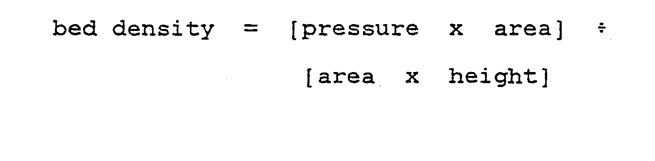
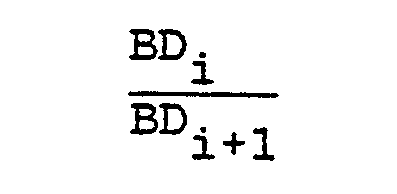
- From observation of fluidized beds, it is known that bed densities at different heights vary in an unpredictable manner. However, it has been found that the relationship between the bed densities of any two adjacent segments, or zones, remained substantially constant, as long as both zones were completely below the bed height. Thus,

- BD = bed density
- i = zone i
- i + 1 = zone i + 1, which is adjacent to and below zone i.
- Referring now to the drawings in detail and in particular to Figure 1, there is shown a fluidized
bed gasification reactor 20, comprising avessel 22, having aproduct gas outlet 24 disposed at its upper end, a fluidizingnozzle 25 extending into the lower portion of thevessel 22, and a fluidizedbed 26 having an upper surface orbed height 27, disposed in the lower portion of thevessel 22, amaterial supply line 28 disposed through thevessel 22 and connected to thenozzle 25, anash discharge 30 at the bottom of thevessel 22, and a bedheight detection system 32 connected to thevessel 22. The bedheight detection system 32 comprisesdifferential pressure detectors 34 attached to and sensing the internal pressure of thevessel 22 and connected by asignal conducting means 35 to a data processing unit 36. The unit 36 provides a signal to acontrol manifold 38 which regulates the flow of feed material from feed lines 40 into thematerial supply line 28. - Referring now to Figure 2, there is shown a partial sectional view of the
vessel 22, containing agas region 50, and abed region 52 containing a mixture of a carbonaceous material, process mediums such as steam, oxygen or air and a combustible gas, and bed density anomalies 54 which may be pockets of carbonaceous material or process mediums. Also shown are, from top, first, second, third and fourthdifferential pressure detectors high pressure tap 64 and alow pressure tap 66, both taps being connected to thevessel 22, with adjacent detectors having acommon tap 68 which connects to thehigh pressure tap 64 for one cell, and thelow pressure tap 66 for an adjacent cell. The high andlow pressure taps bed zone 70. It can be seen that thezone 70 for thefirst detector 56 is completely in thegas region 50, thezone 70 for thesecond detector 58 is partially in thegas region 50, and thezones 70 for the third andfourth detectors bed region 52. - Referring again to Figure 1, during operation of the
gasification reactor 20, feed material such as coal or fines, air or oxygen, steam and a combustible gas (typically cleaned product gas) are injected into thevessel 22 through thenozzle 25, creating a fluidizedbed 27. Ash created in the gasification process is discharged through theash discharge 30, and product gas is discharged through theproduct gas outlet 24. The height of the bed will vary, depending on such factors as vessel temperature and pressure and feed and discharge rates. Thedetectors 34 may provide a continuous input of differential pressure measurements to the data processing unit 36. Using differential pressure measurements from thedetectors 34 thebed height 27 is determined using a method as is set out below. This determination will typically be performed by the data processing unit 36. After thebed height 27 is determined, a signal is generated, typically by the data process unit 36, and conducted to thecontrol manifold 38 which regulates the flow of feed material from feed lines 40 into thematerial supply line 28. Depending on the signal generated, the input rate of one or more of the input feed materials will be modified and thebed height 27 will change accordingly. - The
bed height 27, is determined from the detector measurements by a method which computes the bed height in a real-time environment. This takes into account the rapid changes which occur in the detector measurements as well as the differences in the bed densities in thedifferent detector zones 70. Therefore, the method provides the bed height on the basis of an average value of a number of measurements from each detector rather than instantaneous measurements. - The method is as follows:
- 1. A group of a predetermined number of discrete measurements, typically 10, are collected, or scanned, at a periodic time interval, typically 50 milliseconds apart, from each detector. Both the number of measurements and the time between the measurements can be changed without affecting the method. Each group is taken over a period of time, typically 10 seconds. Thus, 10 measurements would be taken in the first 500 milliseconds of a 10 second period. Measurements taken for the remaining 9.5 seconds of each time period may be disregarded for the calculation of bed height. Each group is averaged, and each average is used in calculating the weight of material per unit volume, or bed density of each zone.




- 2. The most recent of a number, typically 20, of bed densities computed in
step 1 for all the detector zones are maintained and updated with every new bed density. - 3. The last 20 bed densities calculated are averaged for each zone. Then, starting at the zone at the top of the vessel and working downward serially, the average bed densities are reviewed for a non-negative value. If the first non-negative average bed density occurs in detector zone i, then a weight factor WF (a measure of the relationship between the bed densities in the different zones) for detector zone i + 1 is:

- A WF is only valid if the zone for which it is taken is completely within the bed region.
- The WF's for all zones are recalculated every time a new average bed density is calculated to account for changes of material feed to the gasifier.
- 4. The bed height within zone i is calculated in the following manner:

- Note first that the WF for detector zone i will retain the last value calculated for it based either on zone i being completely filled or on a theoretical basis since this zone could only be partially filled with fluidized material at this scan. In initial startup of the system, this WF may be preset using either the WF calculated prior to shutdown of the system or a WF calculated on a theoretical basis. Note also that the quantity

- 5. The bed height within the vessel is determined by adding the bed height within zone i to the height within the vessel to the bottom of zone i. Alternatively, the bed height within zone i can be compared to a reference point other than the bottom of the vessel (such as the middle of the vessel), to show the bed height with respect to that reference.
- After determination of the bed height, the data processing unit produces a signal. This signal is typically an electrical signal, but may be of another type without limiting the invention. The control manifold acts on this signal, either increasing or decreasing some or all of the input materials.
- Example:
- Referring now to Figure 3, there is shown a time interval graph with intervals A and B of 10 seconds length. During the first 500 milliseconds of interval A, 10 differential pressure measurements are taken 50 milliseconds apart, from each detector. At the end of the 500 milliseconds, the 10 differential pressure measurements are averaged to give an average differential pressure for each detector for the
time interval 1. This process is repeated fortime interval 2, and subsequent 10 second time intervals. - Referring to Figure 4, there is shown a time interval graph with
intervals interval 20, for one detector, the bed densities forintervals 1 through 20 are averaged, to give an average bed density. Forinterval 21, the bed densities for a detector forintervals 2 through 21 are averaged. These average bed densities are used in calculation of the weight factor WF, which is recalculated every 10 seconds, using the most recent valid average bed density. Additionally, the bed height is recalculated every 10 seconds, using the most recent bed density calculated, and the most recent valid weight factor WF. - The invention disclosed herein was made or conceived in the course of, or under, a contract with the United States Government identified as No. DE-AC01-80-ET-14752.
Claims (5)

Applications Claiming Priority (2)
| Application Number | Priority Date | Filing Date | Title |
|---|---|---|---|
| US06/377,231 US4421523A (en) | 1982-05-11 | 1982-05-11 | Control of bed height in a fluidized bed gasification system |
| US377231 | 1982-05-11 |
Publications (3)
| Publication Number | Publication Date |
|---|---|
| EP0093801A2 true EP0093801A2 (en) | 1983-11-16 |
| EP0093801A3 EP0093801A3 (en) | 1984-10-03 |
| EP0093801B1 EP0093801B1 (en) | 1987-05-06 |
Family
ID=23488273
Family Applications (1)
| Application Number | Title | Priority Date | Filing Date |
|---|---|---|---|
| EP82111861A Expired EP0093801B1 (en) | 1982-05-11 | 1982-12-21 | Control of bed height in a fluidized bed gasification system |
Country Status (12)
| Country | Link |
|---|---|
| US (1) | US4421523A (en) |
| EP (1) | EP0093801B1 (en) |
| JP (1) | JPS58199037A (en) |
| KR (1) | KR840003035A (en) |
| AU (1) | AU550986B2 (en) |
| BR (1) | BR8207618A (en) |
| CA (1) | CA1194185A (en) |
| DE (1) | DE3276219D1 (en) |
| ES (1) | ES8401518A1 (en) |
| IN (1) | IN156313B (en) |
| YU (1) | YU272282A (en) |
| ZA (1) | ZA828678B (en) |
Cited By (8)
| Publication number | Priority date | Publication date | Assignee | Title |
|---|---|---|---|---|
| GB2144835A (en) * | 1983-08-05 | 1985-03-13 | Energy Equip | Fluidised bed combustors |
| EP0162599A1 (en) * | 1984-04-26 | 1985-11-27 | Carbomedics Inc. | Level control for a fluidized bed |
| EP0183154A3 (en) * | 1984-11-23 | 1987-06-16 | BASF Aktiengesellschaft | Method for the continuous measurement of the degree of filling fluidised-powder apparatuses |
| EP0214417A3 (en) * | 1985-09-02 | 1987-07-01 | Rheinische Braunkohlenwerke AG. | Process for the production of synthesis gas from solid fuels |
| FR2594548A1 (en) * | 1986-02-19 | 1987-08-21 | Bp Chimie Sa | METHOD AND DEVICE FOR DETECTING ANOMALIES IN A FLUIDIZED BED AND APPLICATION TO FLUIDIZED BED REACTORS FOR THE POLYMERIZATION OF GASEOUS PHASE ALPHAOLEFINS |
| EP0167014A3 (en) * | 1984-06-27 | 1987-09-09 | Degussa Aktiengesellschaft | Process for treating fluidized carbon black with gases, fluidizing apparatus for carrying it out and device for indicating the limit of the bed to be used in the apparatus |
| EP0715887A1 (en) * | 1994-12-08 | 1996-06-12 | Basf Aktiengesellschaft | Process for fluidising particles and apparatus for carrying out the process |
| WO2021118751A3 (en) * | 2019-12-11 | 2021-07-15 | Exxonmobil Chemical Patents Inc. | Gas phase production of polyethylene |
Families Citing this family (19)
| Publication number | Priority date | Publication date | Assignee | Title |
|---|---|---|---|---|
| DE3721476C1 (en) * | 1987-06-30 | 1988-12-22 | Asea Brown Boveri | Process for regulating the fluidized bed height in a pyrolysis reactor and arrangement for carrying out the process |
| DE3728982C1 (en) * | 1987-08-29 | 1989-02-16 | Asea Brown Boveri | Process for regulating the height of a fluidized bed |
| JPH05264010A (en) * | 1992-03-19 | 1993-10-12 | Hitachi Ltd | Fluidized bed treatment equipment and pressurized fluidized bed combined cycle power generation equipment |
| US5685640A (en) * | 1993-01-25 | 1997-11-11 | Buhler Ag | Fly ash dosing method for dosing and device therefor |
| AU2001265826A1 (en) * | 2000-06-22 | 2002-01-02 | Chr. Hansen A/S | On-line monitoring and/or control of headspace in a fluid bed reactor system |
| EP1717203A1 (en) * | 2005-04-26 | 2006-11-02 | Kerr-McGee Corporation | Production of titanium tetrachloride using a fluidized bed reactor |
| WO2007094114A1 (en) * | 2006-02-14 | 2007-08-23 | Kureha Corporation | Continuous particulate high-temperature gas treatment apparatus and method of treating |
| ES2526975T3 (en) * | 2010-04-05 | 2015-01-19 | Dow Global Technologies Llc | Process for polymerizing olefin-based polymers containing high molecular weight fractions in condensed and super-condensed modes |
| US8846829B2 (en) | 2011-05-04 | 2014-09-30 | Chevron Phillips Chemical Company Lp | Catalyst feed control during catalyst transition periods |
| AU2012315914B2 (en) | 2011-09-27 | 2015-07-09 | Thermochem Recovery International, Inc. | System and method for syngas clean-up |
| KR101767335B1 (en) | 2016-03-17 | 2017-08-24 | 한국에너지기술연구원 | Differential Pressure Measurement Method and Apparatus for Measurement of Solid Height in a High Temperature and High Pressure Fluidized Bed System |
| EP3433340B1 (en) | 2016-03-25 | 2022-06-29 | ThermoChem Recovery International, Inc. | Three-stage energy-integrated product gas generation system |
| US10364398B2 (en) | 2016-08-30 | 2019-07-30 | Thermochem Recovery International, Inc. | Method of producing product gas from multiple carbonaceous feedstock streams mixed with a reduced-pressure mixing gas |
| US10717102B2 (en) * | 2017-05-31 | 2020-07-21 | Thermochem Recovery International, Inc. | Pressure-based method and system for measuring the density and height of a fluidized bed |
| JP6387480B1 (en) * | 2017-06-22 | 2018-09-05 | 旭化成株式会社 | Method for producing reaction product gas and fluidized bed gas phase reactor |
| CN109429489B (en) * | 2017-06-22 | 2019-12-24 | 旭化成株式会社 | Method for producing reaction gas and fluidized bed gas phase reaction device |
| US11555157B2 (en) | 2020-03-10 | 2023-01-17 | Thermochem Recovery International, Inc. | System and method for liquid fuel production from carbonaceous materials using recycled conditioned syngas |
| TW202432241A (en) | 2022-10-13 | 2024-08-16 | 荷蘭商Asm Ip私人控股有限公司 | Vapor delivery apparatus, vapor phase reactor, and method for monitoring and controlling vapor delivery system |
| WO2025117117A1 (en) * | 2023-11-28 | 2025-06-05 | ExxonMobil Technology and Engineering Company | Quantifying entrainment in a fluidized bed reactor |
Family Cites Families (8)
| Publication number | Priority date | Publication date | Assignee | Title |
|---|---|---|---|---|
| DE135211C (en) * | 1901-05-11 | 1902-10-15 | Ewald Kalthaus | sense with exchangeable blade |
| US2271148A (en) * | 1940-12-31 | 1942-01-27 | Standard Oil Co | Hydrocarbon conversion with suspended catalysts |
| US2534051A (en) * | 1946-11-22 | 1950-12-12 | Standard Oil Dev Co | Method for fluidized low-temperature carbonization of coal |
| FR1009891A (en) * | 1948-07-07 | 1952-06-04 | Otto & Co Gmbh Dr C | Manufacturing process of siliceous bricks |
| GB723653A (en) * | 1951-11-27 | 1955-02-09 | Nat Coal Board | Improved method and apparatus for controlling a fluidised solid mass |
| US4191539A (en) * | 1976-06-07 | 1980-03-04 | Institute Of Gas Technology | Method for feeding caking coal particles to a gasifier |
| GB2033561A (en) * | 1978-09-25 | 1980-05-21 | Flameless Furnaces Ltd | Method of controlling the level of a fluidised bed |
| DE3039210C2 (en) * | 1980-10-17 | 1992-02-27 | Hoechst Ag, 6230 Frankfurt | Digital display of the bulk density and fill level of granular catalysts in a fluidized bed reactor |
-
1982
- 1982-05-11 US US06/377,231 patent/US4421523A/en not_active Expired - Lifetime
- 1982-11-24 ZA ZA828678A patent/ZA828678B/en unknown
- 1982-11-26 AU AU90911/82A patent/AU550986B2/en not_active Ceased
- 1982-11-26 IN IN1377/CAL/82A patent/IN156313B/en unknown
- 1982-12-08 JP JP57216236A patent/JPS58199037A/en active Pending
- 1982-12-09 YU YU02722/82A patent/YU272282A/en unknown
- 1982-12-16 CA CA000417851A patent/CA1194185A/en not_active Expired
- 1982-12-21 DE DE8282111861T patent/DE3276219D1/en not_active Expired
- 1982-12-21 EP EP82111861A patent/EP0093801B1/en not_active Expired
- 1982-12-30 BR BR8207618A patent/BR8207618A/en unknown
-
1983
- 1983-01-04 KR KR1019830000006A patent/KR840003035A/en not_active Ceased
- 1983-01-10 ES ES518863A patent/ES8401518A1/en not_active Expired
Cited By (12)
| Publication number | Priority date | Publication date | Assignee | Title |
|---|---|---|---|---|
| GB2144835A (en) * | 1983-08-05 | 1985-03-13 | Energy Equip | Fluidised bed combustors |
| EP0162599A1 (en) * | 1984-04-26 | 1985-11-27 | Carbomedics Inc. | Level control for a fluidized bed |
| AU572986B2 (en) * | 1984-04-26 | 1988-05-19 | Carbomedics Inc. | Level control for a fluidized bed |
| EP0167014A3 (en) * | 1984-06-27 | 1987-09-09 | Degussa Aktiengesellschaft | Process for treating fluidized carbon black with gases, fluidizing apparatus for carrying it out and device for indicating the limit of the bed to be used in the apparatus |
| EP0183154A3 (en) * | 1984-11-23 | 1987-06-16 | BASF Aktiengesellschaft | Method for the continuous measurement of the degree of filling fluidised-powder apparatuses |
| EP0214417A3 (en) * | 1985-09-02 | 1987-07-01 | Rheinische Braunkohlenwerke AG. | Process for the production of synthesis gas from solid fuels |
| FR2594548A1 (en) * | 1986-02-19 | 1987-08-21 | Bp Chimie Sa | METHOD AND DEVICE FOR DETECTING ANOMALIES IN A FLUIDIZED BED AND APPLICATION TO FLUIDIZED BED REACTORS FOR THE POLYMERIZATION OF GASEOUS PHASE ALPHAOLEFINS |
| EP0233787A1 (en) * | 1986-02-19 | 1987-08-26 | BP Chemicals Limited | The detection of anomolies in gas fluidised bed polymerisation |
| US4858144A (en) * | 1986-02-19 | 1989-08-15 | Bp Chemicals Limited | Detection of anomalies in gas fluidized bed polymerization |
| EP0715887A1 (en) * | 1994-12-08 | 1996-06-12 | Basf Aktiengesellschaft | Process for fluidising particles and apparatus for carrying out the process |
| US5752327A (en) * | 1994-12-08 | 1998-05-19 | Basf Aktiengesellschaft | Particle fluidization method and apparatus therefor |
| WO2021118751A3 (en) * | 2019-12-11 | 2021-07-15 | Exxonmobil Chemical Patents Inc. | Gas phase production of polyethylene |
Also Published As
| Publication number | Publication date |
|---|---|
| AU9091182A (en) | 1983-11-17 |
| EP0093801A3 (en) | 1984-10-03 |
| BR8207618A (en) | 1984-04-17 |
| ES518863A0 (en) | 1983-12-16 |
| KR840003035A (en) | 1984-08-13 |
| DE3276219D1 (en) | 1987-06-11 |
| ZA828678B (en) | 1983-10-26 |
| CA1194185A (en) | 1985-09-24 |
| IN156313B (en) | 1985-06-22 |
| JPS58199037A (en) | 1983-11-19 |
| AU550986B2 (en) | 1986-04-10 |
| YU272282A (en) | 1985-04-30 |
| EP0093801B1 (en) | 1987-05-06 |
| ES8401518A1 (en) | 1983-12-16 |
| US4421523A (en) | 1983-12-20 |
Similar Documents
| Publication | Publication Date | Title |
|---|---|---|
| EP0093801B1 (en) | Control of bed height in a fluidized bed gasification system | |
| Svensson et al. | Bottom bed regimes in a circulating fluidized bed boiler | |
| EP2084194B1 (en) | Method and apparatus for controlling static charge in polyolefin reactors | |
| DE69117210T2 (en) | Method and device for determining the mass flow of pneumatically conveyed solids | |
| EP0028021B1 (en) | Method and apparatus for pyrolyzing | |
| US4073628A (en) | Control system for apparatus to gasify fine-grain fuels in a reactor | |
| US4936870A (en) | Process for determination and control of fuel mass flow in partial oxidation and gasification of a fine-grained to powdery fuel | |
| JPH03128990A (en) | Method and deive for pneumatically conveying particulate or dust-like fuel from storage bunker under atmospheric pressure into gasifier under raised pressure | |
| US5554202A (en) | Gasifier monitoring apparatus | |
| US3322521A (en) | Process and apparatus for the gasifica- tion of ash-containing fuel | |
| EP0308026B1 (en) | Feed vessel apparatus for coal gasification | |
| US20230220288A1 (en) | Circulation control in dual bed gasifiers | |
| US3874739A (en) | Method and apparatus for the transfer of entrained solids | |
| Lewis et al. | Low-temperature oxidation of carbon | |
| KR102811140B1 (en) | Method for preventing clogging of circulating bed material in a circulating fluidized bed reactor arrangement | |
| US4869622A (en) | Feed hopper design | |
| US4889540A (en) | Apparatus for determination of slag tap blockage | |
| US4768468A (en) | Method of controlling a fluidized bed boiler | |
| US5112366A (en) | Slag deposition detection | |
| US4750434A (en) | Mill/dryer gas temperature control | |
| US4038045A (en) | Process for degasifying fine-grained fuels | |
| JP2508119B2 (en) | Fluidized bed boiler control method | |
| AU607536B2 (en) | Feed vessel apparatus for coal gasification | |
| Holden | Operation of Pressure-gasification Pilot Plant Utilizing Pulverized Coal and Oxygen, a Progress Report | |
| KAWABATA et al. | Gasification of coal char in a two-stage pressurized fluidized bed |
Legal Events
| Date | Code | Title | Description |
|---|---|---|---|
| PUAI | Public reference made under article 153(3) epc to a published international application that has entered the european phase |
Free format text: ORIGINAL CODE: 0009012 |
|
| AK | Designated contracting states |
Designated state(s): BE DE FR GB IT |
|
| PUAL | Search report despatched |
Free format text: ORIGINAL CODE: 0009013 |
|
| AK | Designated contracting states |
Designated state(s): BE DE FR GB IT |
|
| RAP1 | Party data changed (applicant data changed or rights of an application transferred) |
Owner name: KRW ENERGY SYSTEMS INC. |
|
| 17P | Request for examination filed |
Effective date: 19850301 |
|
| ITF | It: translation for a ep patent filed | ||
| GRAA | (expected) grant |
Free format text: ORIGINAL CODE: 0009210 |
|
| AK | Designated contracting states |
Kind code of ref document: B1 Designated state(s): BE DE FR GB IT |
|
| REF | Corresponds to: |
Ref document number: 3276219 Country of ref document: DE Date of ref document: 19870611 |
|
| ET | Fr: translation filed | ||
| PLBE | No opposition filed within time limit |
Free format text: ORIGINAL CODE: 0009261 |
|
| STAA | Information on the status of an ep patent application or granted ep patent |
Free format text: STATUS: NO OPPOSITION FILED WITHIN TIME LIMIT |
|
| 26N | No opposition filed | ||
| ITTA | It: last paid annual fee | ||
| PGFP | Annual fee paid to national office [announced via postgrant information from national office to epo] |
Ref country code: FR Payment date: 19931112 Year of fee payment: 12 |
|
| PGFP | Annual fee paid to national office [announced via postgrant information from national office to epo] |
Ref country code: BE Payment date: 19940114 Year of fee payment: 12 |
|
| PG25 | Lapsed in a contracting state [announced via postgrant information from national office to epo] |
Ref country code: BE Effective date: 19941231 |
|
| BERE | Be: lapsed |
Owner name: KRW ENERGY SYSTEMS INC. Effective date: 19941231 |
|
| PG25 | Lapsed in a contracting state [announced via postgrant information from national office to epo] |
Ref country code: FR Effective date: 19950831 |
|
| REG | Reference to a national code |
Ref country code: FR Ref legal event code: ST |
|
| PGFP | Annual fee paid to national office [announced via postgrant information from national office to epo] |
Ref country code: GB Payment date: 19951123 Year of fee payment: 14 |
|
| PGFP | Annual fee paid to national office [announced via postgrant information from national office to epo] |
Ref country code: DE Payment date: 19951129 Year of fee payment: 14 |
|
| PG25 | Lapsed in a contracting state [announced via postgrant information from national office to epo] |
Ref country code: GB Effective date: 19961221 |
|
| GBPC | Gb: european patent ceased through non-payment of renewal fee |
Effective date: 19961221 |
|
| PG25 | Lapsed in a contracting state [announced via postgrant information from national office to epo] |
Ref country code: DE Effective date: 19970902 |