EP0093825A1 - Verfahren und Vorrichtung zur Beseitigung von Müll - Google Patents
Verfahren und Vorrichtung zur Beseitigung von Müll Download PDFInfo
- Publication number
- EP0093825A1 EP0093825A1 EP82850104A EP82850104A EP0093825A1 EP 0093825 A1 EP0093825 A1 EP 0093825A1 EP 82850104 A EP82850104 A EP 82850104A EP 82850104 A EP82850104 A EP 82850104A EP 0093825 A1 EP0093825 A1 EP 0093825A1
- Authority
- EP
- European Patent Office
- Prior art keywords
- refuse
- storage chamber
- removal
- container
- receiving container
- Prior art date
- Legal status (The legal status is an assumption and is not a legal conclusion. Google has not performed a legal analysis and makes no representation as to the accuracy of the status listed.)
- Withdrawn
Links
- 239000002699 waste material Substances 0.000 title claims abstract description 19
- 238000000034 method Methods 0.000 title claims abstract description 9
- 238000003860 storage Methods 0.000 claims abstract description 24
- 238000012432 intermediate storage Methods 0.000 claims description 3
- 238000005056 compaction Methods 0.000 claims description 2
- 238000009434 installation Methods 0.000 description 3
- 208000008035 Back Pain Diseases 0.000 description 2
- 208000019804 backache Diseases 0.000 description 2
- 238000012423 maintenance Methods 0.000 description 2
- 230000009467 reduction Effects 0.000 description 2
- 230000008439 repair process Effects 0.000 description 2
- 230000009471 action Effects 0.000 description 1
- 238000007664 blowing Methods 0.000 description 1
- 230000015556 catabolic process Effects 0.000 description 1
- 230000006378 damage Effects 0.000 description 1
- 238000006731 degradation reaction Methods 0.000 description 1
- 230000008021 deposition Effects 0.000 description 1
- 238000007689 inspection Methods 0.000 description 1
- 239000000463 material Substances 0.000 description 1
- 238000012856 packing Methods 0.000 description 1
- 230000008569 process Effects 0.000 description 1
- 238000000926 separation method Methods 0.000 description 1
- 238000004056 waste incineration Methods 0.000 description 1
Images

Classifications
-
- B—PERFORMING OPERATIONS; TRANSPORTING
- B65—CONVEYING; PACKING; STORING; HANDLING THIN OR FILAMENTARY MATERIAL
- B65F—GATHERING OR REMOVAL OF DOMESTIC OR LIKE REFUSE
- B65F5/00—Gathering or removal of refuse otherwise than by receptacles or vehicles
- B65F5/005—Gathering or removal of refuse otherwise than by receptacles or vehicles by pneumatic means, e.g. by suction
Definitions
- the present invention relates to a method and a system for mechanized waste management, in particular of domestic refuse, from the deposition of the refuse, for instance in a refuse storage chamber, until its conveyance to a waste deposit, incineration plant or the like.
- the partly mechanized systems normally relate to mechanization of the removal of the refuse from the area where it is produced.
- This mechanization consists in specially designed vehicles to which the refuse is transported manually, whereupon it is mechanically lifted into and packed in the vehicle in order thereafter to be dumped at a plant for storage or degradation.
- a fully mechanized system that has been in use for some years consists of a pipe system which is integrated in the refuse assembling area and in which the refuse is transported by suction from a refuse storage chamber close to the users, to a collecting place which may be an intermediate storage space, a waste incineration plant or the like.
- mechanization are refuse sack changers with automatic packing.
- mechanized transport systems in the form of screw conveyors, conveyor belts, lifts and the like. This transportation has taken place within the building itself, from where the refuse has then been manually transported to the refuse-collecting vehicle.
- waste mills for grinding the refuse in order to obtain an enhanced degree of compaction so as to reduce transport costs.
- the object of the present invention is to meet current demands on the working environment in connection with waste management and to do so in a way to keep costs on an acceptable level and at the same time satisfy the demands of the users on convenience.
- the invention may be described as a method and a system for waste management by removal of refuse from a refuse storage chamber located in a building to a final deposit, the novel feature of the invention being that the removal is carried out in a closed mobile system.
- the system is thus completely closed. This means that no human hand should need to touch the refuse once it has been deposited in the refuse chute or the like.
- optimum hygiene is obtained in the waste management process and current injuries to dustmen and caretakers, such as backache and cuts, are avoided.
- Backache may result from lifting refuse sacks during re-stacking or removal thereof. Cuts are caused by sharp objects cutting through the sacks.
- the system is easy to handle and does not allow for alternative waste management. This is important since experience has shown that many of today's dustmen do not use mechanical aids, such as conveyor belts and the like, because of the time consumption involved. Thus, where possible, a faster familiar routine is preferred, irrespective of bodily risks and after-effects.
- the invention here presented means that all existing refuse storage chambers are maintained and that the comfort of the tenants is not deteriorated.
- the invention can thus be said to constitute an overall solution, like the stationary pneumatic disposal units, but at only a fraction of the investment costs thereof and with considerably enhanced reliability and accessability in the event of disturbances. Further, the system according to the invention offers a flexibility which means that it may easily be modified according to the development within the field of conveying technique and in compliance with demands on refuse separation and the like.
- Fig. 1 in perspective obliquely from above and with certain parts broken away, shows a container being part of the invention, and the equipment associated therewith.
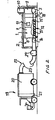
- Fig. 2 schematically from the side, shows the container of Fig. 1 as disposed in a refuse storage chamber and connected to a vehicle for removing the refuse.
- a substantially parallelepipedal receiving container 1 is placed in an existing refuse storage chamber 2 in a building (not shown in greater detail) and is of such a volume as to hold for example one week's deposit of refuse.
- the container 1 has three bottom walls 3, 4 and 5 slanting inwardly towards its lowermost point, two vertical long sides 6 and 7, and two vertical short sides 8 and 9.
- At the short side 9 which is connected to a refuse chute 10 opening in the refuse storage chamber 2, there is mounted an inflatable bag 11 of rubber or similar material which has a specially designed profile.
- a transport device 12 in the form of a rotary waste conveyor screw 13.
- This screw is connected at one end to a drive, for instance an electric motor 14, which is mounted on the outer side of the short side 8 of the container 1.
- a part-circular waste collecting duct 15 Parallel to and underneath the conveyor screw 13 there is a part-circular waste collecting duct 15 which has a circular connecting discharge 16 at the short side 8 of the container 1.
- the long side 7 there is also an inspection cover 17 through which it is possible to supervise the management of the refuse and withdraw such refuse as either is too bulky or must be disintegrated manually. To permit displacing the container 1 for maintenance and/or repairs, it rests on suitable transport wheels 18.
- the system according to the invention also includes a transport vehicle 19, see Fig. 2, which is equipped with a collecting tank 20, a vacuum pump 21, and a tube equipment 22.
- a transport vehicle 19 see Fig. 2, which is equipped with a collecting tank 20, a vacuum pump 21, and a tube equipment 22.
- the other components and details of the transport vehicle 19 are not comprised by the invention and thus need not be described here.
- Waste management is carried out by means of the above-described system in the following way.
- the inflatable bag 11 is automatically pumped up at preset intervals.
- This bag has a volume larger at the top than at the bottom, such that the top of the refuse layer will be pressed away towards the other end of the receiving container 1.
- the container 1 has slanting bottom walls 3, 4, 5, the refuse will descend towards the conveyor screw 13 being on a level with the bottom of the container.
- the electric motor 14 is started for rotation of the conveyor screw 13.
- the refuse will be pressed out into the part-circular collecting duct 15, from where it is sucked out through the connecting discharge 16 with the aid of a tube 23 which is part of the tube equipment 22 and connected at one end to the discharge 16 and at the opposite end to the collecting tank 20 of the transport vehicle 19, suction being produced by the vacuum pump 21 mounted on the transport vehicle 19.
- the receiving container 1 has been emptied, the vehicle is driven to the next refuse storage chamber and the same procedure is repeated.
- the transport vehicle 19 is driven to an intermediate waste storage site or to a waste deposit for emptying, which is done by tipping or blowing out the refuse. The vehicle is then driven to the next refuse storage chamber to be emptied and so forth.
- a suitable waste grinder for instance a so-called jaw crusher 24, in the tube equipment 22, suitably between the tube 23 and the connecting discharge 16.
- This jaw crusher is suitably so designed that the refuse is sucked therethrough under the action of the vacuum pump 21 at the same time as the disintegrating means, generally a rotating spiked roller or the like, of the jaw crusher is rotated by means of a separate motor (not shown).
- one or more inflatable bellows of rubber or the like can be provided on or in the bottom and/or walls of the container 1, such bellows means being shown at 25 in Fig. 1.
- the one or many bellows 25, like the inflatable bag 11, can be pumped up automatically at preset intervals or manually, when required.
Landscapes
- Refuse Collection And Transfer (AREA)
Priority Applications (1)
| Application Number | Priority Date | Filing Date | Title |
|---|---|---|---|
| EP82850104A EP0093825A1 (de) | 1982-05-07 | 1982-05-07 | Verfahren und Vorrichtung zur Beseitigung von Müll |
Applications Claiming Priority (1)
| Application Number | Priority Date | Filing Date | Title |
|---|---|---|---|
| EP82850104A EP0093825A1 (de) | 1982-05-07 | 1982-05-07 | Verfahren und Vorrichtung zur Beseitigung von Müll |
Publications (1)
| Publication Number | Publication Date |
|---|---|
| EP0093825A1 true EP0093825A1 (de) | 1983-11-16 |
Family
ID=8190148
Family Applications (1)
| Application Number | Title | Priority Date | Filing Date |
|---|---|---|---|
| EP82850104A Withdrawn EP0093825A1 (de) | 1982-05-07 | 1982-05-07 | Verfahren und Vorrichtung zur Beseitigung von Müll |
Country Status (1)
| Country | Link |
|---|---|
| EP (1) | EP0093825A1 (de) |
Cited By (7)
| Publication number | Priority date | Publication date | Assignee | Title |
|---|---|---|---|---|
| US5845566A (en) * | 1998-04-30 | 1998-12-08 | Lee; Ming-Fong | Multi-slot closed type powerful garbage compression structure |
| WO2003057603A1 (en) * | 2002-01-09 | 2003-07-17 | Envac Centralsug Ab | Method for processing kitchen waste |
| WO2008153448A1 (en) * | 2007-06-11 | 2008-12-18 | Envac Ab | Waste collection facility with storage tank and service space |
| EP1163173B2 (de) † | 1999-02-05 | 2009-05-20 | Envac AB | Verfahren und vorrichtung zum entleeren des inhalts eines stauraumes in einem mülltransportsystem |
| WO2010090574A1 (en) * | 2009-02-03 | 2010-08-12 | Envac Ab | A vacuum operated waste collection container and a use of the container |
| CN102811926A (zh) * | 2010-02-12 | 2012-12-05 | 马里凯普有限公司 | 用于在气动式物料搬运系统中搬运物料的方法和设备 |
| WO2014029903A1 (en) | 2012-08-22 | 2014-02-27 | Maricap Oy | Method for handling material in a material conveying system, material conveying system and a separating device for a material conveying system |
Citations (7)
| Publication number | Priority date | Publication date | Assignee | Title |
|---|---|---|---|---|
| US2583648A (en) * | 1948-12-21 | 1952-01-29 | Golden State Company Ltd | Powder conveying method and apparatus |
| FR1385399A (fr) * | 1963-08-29 | 1965-01-15 | Dispositif pour transformation et transport des ordures ménagères | |
| DE2208586B1 (de) * | 1972-02-23 | 1973-06-14 | Keller & Knappich Augsburg, Zweigniederlassung Der Industrie-Werke Karlsruhe Augsburg Ag, 8900 Augsburg | Saugluftförderanlage fur Mull |
| FR2215352A2 (de) * | 1973-01-26 | 1974-08-23 | Mecaniques Ste Artesienne Cons | |
| DE2504212A1 (de) * | 1975-02-01 | 1976-08-05 | Karlsruhe Augsburg Iweka | Vorrichtung zum entsorgen von haus-, geschaefts- und/oder industriemuell |
| DE2513290A1 (de) * | 1975-03-26 | 1976-10-07 | Jansky Tank & App | Muellfahrzeug |
| GB1581925A (en) * | 1977-04-19 | 1980-12-31 | Massey Ferguson Sa | Combine harvesters |
-
1982
- 1982-05-07 EP EP82850104A patent/EP0093825A1/de not_active Withdrawn
Patent Citations (7)
| Publication number | Priority date | Publication date | Assignee | Title |
|---|---|---|---|---|
| US2583648A (en) * | 1948-12-21 | 1952-01-29 | Golden State Company Ltd | Powder conveying method and apparatus |
| FR1385399A (fr) * | 1963-08-29 | 1965-01-15 | Dispositif pour transformation et transport des ordures ménagères | |
| DE2208586B1 (de) * | 1972-02-23 | 1973-06-14 | Keller & Knappich Augsburg, Zweigniederlassung Der Industrie-Werke Karlsruhe Augsburg Ag, 8900 Augsburg | Saugluftförderanlage fur Mull |
| FR2215352A2 (de) * | 1973-01-26 | 1974-08-23 | Mecaniques Ste Artesienne Cons | |
| DE2504212A1 (de) * | 1975-02-01 | 1976-08-05 | Karlsruhe Augsburg Iweka | Vorrichtung zum entsorgen von haus-, geschaefts- und/oder industriemuell |
| DE2513290A1 (de) * | 1975-03-26 | 1976-10-07 | Jansky Tank & App | Muellfahrzeug |
| GB1581925A (en) * | 1977-04-19 | 1980-12-31 | Massey Ferguson Sa | Combine harvesters |
Cited By (14)
| Publication number | Priority date | Publication date | Assignee | Title |
|---|---|---|---|---|
| US5845566A (en) * | 1998-04-30 | 1998-12-08 | Lee; Ming-Fong | Multi-slot closed type powerful garbage compression structure |
| EP1163173B2 (de) † | 1999-02-05 | 2009-05-20 | Envac AB | Verfahren und vorrichtung zum entleeren des inhalts eines stauraumes in einem mülltransportsystem |
| WO2003057603A1 (en) * | 2002-01-09 | 2003-07-17 | Envac Centralsug Ab | Method for processing kitchen waste |
| CN101801813B (zh) * | 2007-06-11 | 2013-07-03 | 恩华特公司 | 一种废物收集和暂时存储设备及其生产方法 |
| WO2008153448A1 (en) * | 2007-06-11 | 2008-12-18 | Envac Ab | Waste collection facility with storage tank and service space |
| WO2010090574A1 (en) * | 2009-02-03 | 2010-08-12 | Envac Ab | A vacuum operated waste collection container and a use of the container |
| AU2010211396B2 (en) * | 2009-02-03 | 2015-01-15 | Envac Ab | A vacuum operated waste collection container and a use of the container |
| CN102811926A (zh) * | 2010-02-12 | 2012-12-05 | 马里凯普有限公司 | 用于在气动式物料搬运系统中搬运物料的方法和设备 |
| CN102811927A (zh) * | 2010-02-12 | 2012-12-05 | 马里凯普有限公司 | 用于在气动式管道输送系统中搬运物料的方法和设备 |
| US20120304873A1 (en) * | 2010-02-12 | 2012-12-06 | Maricap Oy | Method and apparatus for handling material in a pneumatic pipe transport system |
| CN102822072A (zh) * | 2010-02-12 | 2012-12-12 | 马里凯普有限公司 | 用于在气动式物料搬运系统中搬运物料的方法和设备 |
| US9139362B2 (en) * | 2010-02-12 | 2015-09-22 | Maricap Oy | Method and apparatus for handling material in a pneumatic pipe transport system |
| CN102811927B (zh) * | 2010-02-12 | 2016-04-06 | 马里凯普有限公司 | 用于在气动式管道输送系统中搬运物料的方法和设备 |
| WO2014029903A1 (en) | 2012-08-22 | 2014-02-27 | Maricap Oy | Method for handling material in a material conveying system, material conveying system and a separating device for a material conveying system |
Similar Documents
| Publication | Publication Date | Title |
|---|---|---|
| EP0708039B1 (de) | Müllsammelvorrichtung sowie Entleerungs- und Transportvorrichtung dafür | |
| US4423987A (en) | Garbage conveying system | |
| CN111647441B (zh) | 一种气化炉预处理和进料系统 | |
| WO2022189697A1 (en) | Method for conveying material and material conveying arrangement | |
| US20130004249A1 (en) | Method and apparatus in a pneumatic material conveying system, and a waste conveying system | |
| CN106742992A (zh) | 一种垃圾智能收集系统及方法 | |
| CN205327944U (zh) | 垃圾压缩机 | |
| EP1056661B1 (de) | Verfahren und zugehörige anlagen zur behandlung und entsorgung von müll | |
| KR20150004632A (ko) | 재활용 쓰레기 처리장치 | |
| CN206782602U (zh) | 一种垃圾智能收集系统 | |
| JPS60157096A (ja) | 圧縮促進装置 | |
| EP0500004B1 (de) | Verfahren und Vorrichtung zur Rückgewinnung von wiederverwertbarem Abfall von Behältern oder dergleichen aus wiederverwertbarem Kunststoff | |
| JPH10211442A (ja) | コンベア式廃蛍光管破砕処理保管装置 | |
| CN211839044U (zh) | 存量垃圾筛分装置 | |
| CN206142270U (zh) | 一种压缩中转站垃圾量显示控制系统 | |
| KR102910282B1 (ko) | 음식물 봉투 투입기를 갖춘 음폐기물 수거 및 운반 차량 | |
| JPH0462963B2 (de) | ||
| JPS649061B2 (de) | ||
| CN221564968U (zh) | 一种移动卸料装置 | |
| CN214826176U (zh) | 一种建筑废弃物回收用储存投放垃圾的料仓 | |
| CN212040903U (zh) | 一种轻重建筑垃圾分离装置 | |
| JPH03111304A (ja) | ごみ収集装置 | |
| JPH03111303A (ja) | 中高層建築物の塵芥処理システム | |
| JP3197127B2 (ja) | 古紙回収装置 | |
| WO2016120519A1 (en) | Method for handling material in a material conveying system, material conveying system and a separating device for a material conveying system |
Legal Events
| Date | Code | Title | Description |
|---|---|---|---|
| PUAI | Public reference made under article 153(3) epc to a published international application that has entered the european phase |
Free format text: ORIGINAL CODE: 0009012 |
|
| AK | Designated contracting states |
Designated state(s): AT BE CH DE FR GB IT LI LU NL SE |
|
| 17P | Request for examination filed |
Effective date: 19831216 |
|
| STAA | Information on the status of an ep patent application or granted ep patent |
Free format text: STATUS: THE APPLICATION IS DEEMED TO BE WITHDRAWN |
|
| 18D | Application deemed to be withdrawn |
Effective date: 19860129 |
|
| RIN1 | Information on inventor provided before grant (corrected) |
Inventor name: SVENSSON, SVEN-OLOF Inventor name: BAERTZNER, KJELL Inventor name: MAEKK, OLEV Inventor name: BENGTSSON, HARRY |