EP0093879B1 - Procédé et dispositif de dosage d'encre dans les rotatives offset - Google Patents
Procédé et dispositif de dosage d'encre dans les rotatives offset Download PDFInfo
- Publication number
- EP0093879B1 EP0093879B1 EP83103480A EP83103480A EP0093879B1 EP 0093879 B1 EP0093879 B1 EP 0093879B1 EP 83103480 A EP83103480 A EP 83103480A EP 83103480 A EP83103480 A EP 83103480A EP 0093879 B1 EP0093879 B1 EP 0093879B1
- Authority
- EP
- European Patent Office
- Prior art keywords
- ink
- metering
- cylinder
- ink cylinder
- metering device
- Prior art date
- Legal status (The legal status is an assumption and is not a legal conclusion. Google has not performed a legal analysis and makes no representation as to the accuracy of the status listed.)
- Expired
Links
- 238000007645 offset printing Methods 0.000 title claims description 9
- 238000000034 method Methods 0.000 title claims description 8
- 239000000463 material Substances 0.000 claims description 8
- 239000002826 coolant Substances 0.000 claims description 5
- 230000001105 regulatory effect Effects 0.000 claims description 5
- 238000006073 displacement reaction Methods 0.000 claims description 2
- 230000003247 decreasing effect Effects 0.000 claims 1
- 239000003973 paint Substances 0.000 description 26
- 238000007639 printing Methods 0.000 description 21
- 238000004519 manufacturing process Methods 0.000 description 4
- 238000010276 construction Methods 0.000 description 3
- 238000001816 cooling Methods 0.000 description 2
- 238000010586 diagram Methods 0.000 description 2
- 206010016256 fatigue Diseases 0.000 description 2
- 239000002184 metal Substances 0.000 description 2
- 239000002245 particle Substances 0.000 description 2
- 230000002093 peripheral effect Effects 0.000 description 2
- 229910000831 Steel Inorganic materials 0.000 description 1
- 230000001154 acute effect Effects 0.000 description 1
- 238000004026 adhesive bonding Methods 0.000 description 1
- 238000005452 bending Methods 0.000 description 1
- 239000003795 chemical substances by application Substances 0.000 description 1
- 239000003086 colorant Substances 0.000 description 1
- 230000006835 compression Effects 0.000 description 1
- 238000007906 compression Methods 0.000 description 1
- 239000000110 cooling liquid Substances 0.000 description 1
- 230000000694 effects Effects 0.000 description 1
- 239000007788 liquid Substances 0.000 description 1
- 239000010893 paper waste Substances 0.000 description 1
- 230000035515 penetration Effects 0.000 description 1
- 238000005293 physical law Methods 0.000 description 1
- 238000011084 recovery Methods 0.000 description 1
- 238000007789 sealing Methods 0.000 description 1
- 125000006850 spacer group Chemical group 0.000 description 1
- 239000010959 steel Substances 0.000 description 1
- 239000000758 substrate Substances 0.000 description 1
- 239000002699 waste material Substances 0.000 description 1
- XLYOFNOQVPJJNP-UHFFFAOYSA-N water Substances O XLYOFNOQVPJJNP-UHFFFAOYSA-N 0.000 description 1
- 238000004804 winding Methods 0.000 description 1
Images




Classifications
-
- B—PERFORMING OPERATIONS; TRANSPORTING
- B41—PRINTING; LINING MACHINES; TYPEWRITERS; STAMPS
- B41F—PRINTING MACHINES OR PRESSES
- B41F31/00—Inking arrangements or devices
- B41F31/02—Ducts, containers, supply or metering devices
- B41F31/04—Ducts, containers, supply or metering devices with duct-blades or like metering devices
Definitions
- the invention relates to a method and a device for metering the color in offset printing machines according to the preamble of claim 1.
- EPU, EPA-0 078 444 is a so-called short inking unit, in which no large number of inking units are provided, which processes the amount of ink supplied into a very thin ink film, as required for inking the printing plate becomes.
- the problem with these inking units is to feed this thin ink film of a few f.Lm thickness absolutely evenly over the plate length and in a constant thickness during printing. Even the production of such a thin and absolutely constant color film was not suggested by the prior art.
- the inking of the application roller takes place in the known embodiment by means of an ink reservoir, which is arranged in the area of the lateral surface of the application roller.
- the excess paint is wiped off the outer surface with a color knife until the ink film required in the respective zone just remains on the outer surface of the application roller.
- This ink film is then evened out by two rollers before it is applied to the printing plate.
- the ink knife acting as a metering body is pressed in the known embodiment under such high pressure against the elastic outer surface of the applicator roller that its surface is impressed considerably in the area of the scraper edge, so that an ink film can be produced in the desired small film thickness.
- the application roller is driven at the peripheral speed of the plate cylinder.
- the heat generated by the color knife which is set as hard as described, not only leads to early fatigue of the material, but also to a considerable increase in temperature. Since the temperature has a significant influence on the viscosity of the paint, the amount of paint transferred changes considerably.
- the rubber jacket creates a natural vibration that leads to changes in the color gap and thus also to color fluctuations. This vibration depends on the respective recovery capacity of the material, i. H. also from his state of fatigue. An exact and high-quality inking of the printing plate is impossible because with the known design a reproducible, i.e. H. constant amount of paint cannot be set in all operating conditions.
- the object of the invention is a method and to create an ink metering device for carrying out the method for producing an absolutely uniform and reproducible ink supply in offset printing presses, which ensures exact regulation of the inking of the plate cylinder in an inking unit with only a few inking unit rollers with little effort.
- the object is achieved by the features of claim 1, claims 2 and 4 having an additional control circuit and an additional coolant circuit.
- the advantage achieved with the described solution is that, given the dynamic pressure of the ink, a constant, predeterminable layer thickness is achieved by regulating various parameters due to the physical laws, so that even when the hydrodynamic pressure changes, the ink is precise and uniform Printing result is achieved.
- the use of a rigid ink cylinder considerably restricts the number of interferences, wear and tear on the outer surface of the ink cylinder and color fluctuations due to the rigid outer surface of the ink cylinder being excluded.
- a thin ink film which is always fed to the printing form in the same layer thickness generally does not need to be adapted to the ink consumption which differs zonally across the width of the form.
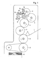
- Fig. 1 shows schematically an offset printing machine, in which the sheets to be printed are fed in a known manner via a feeder 1 to a printing cylinder 2, which cooperates with a blanket cylinder 3 and a plate cylinder 4. The print image is thus transferred from the plate cylinder 4 via the rubber cylinder 3 to the sheet to be printed on the printing cylinder 2. After printing, the sheet is fed from a chain delivery 5 to a delivery stack 6.
- the plate cylinder 4 is assigned an inking roller 7, which has an elastic jacket surface and preferably has a plate cylinder diameter.
- the inking roller 7 in turn receives its color from an ink cylinder 8, which has an outer surface made of rigid material, for. B. metal is provided.
- the dampening unit 9 transfers the dampening solution via the two applicator rollers 10 and 11 to the ink cylinder, the last applicator roller 11, viewed in the direction of rotation, being pivotally mounted on the plate cylinder 4 for faster moistening (shown in broken lines).
- the ink cylinder 8 is assigned a metering body 12, which is supported on a crossmember 13, which is fastened to the side frames, via compression springs with a flat characteristic curve and ball joints 19.
- the ink supply 14 is located in the gap between the ink cylinder 8 and the metering body 12.
- sensors 15 are provided which measure the layer thickness of the ink on the ink cylinder 8.
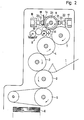
- the embodiment according to FIG. 2 differs in that 8 cross members 16 and 17 are provided on both sides of the ink cylinder.
- a metering body 18 is supported on the crossmember 16 via a ball joint 19 and a pressure medium cylinder 20.
- the pressure cylinder 20 with the ball joints. 19 are arranged along the length of the ink cylinder in close succession, so that with the same loading of the pressure medium cylinder 20 there is a contact pressure evenly distributed over the entire width of the ink cylinder 8.
- the control of the exposure takes place as a function of the viscosity of the ink in the metering gap and / or the dampening agent supply and / or the peripheral speed of the ink cylinder, such that a constant, predeterminable layer thickness of the ink on the ink cylinder or a constant, predeterminable intensity of the color impression on the printing substrate given is.
- the layer thickness of the paint can be precisely measured here via the sensors 15, which are arranged in zones. A zonal influencing of the layer thickness is indivi duel differentiated loading of the pressure medium cylinder 20 may be possible.
- a supporting body 21 is supported on the crossmember 17 and is also pressed in zones by pressure medium cylinders 22 via ball joints 23.
- Each pressure medium cylinder 22 can thus exert the same pressure as the opposite pressure medium cylinder 20, so that the pressure forces acting on the ink cylinder cancel each other out. This reliably prevents the ink cylinder 8 from bending.
- the ink cylinder 8 has a chamber 24 which can be filled with a cooling liquid. This ensures that the temperature of the ink and the ink cylinder 8 in a decoupled control loop, regardless of the pressure of the ink, is kept constant in the metering gap on a given work.
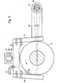
- FIG. 3 shows a color metering device according to FIG. 2 in a partial longitudinal section with a mounting of the ink cylinder 8 via roller bearings 25 in the machine side frames 26 and 27.
- the outer surface 28 of the ink cylinder 8 is made of metal and rests on the end faces and sealing jaws 29 for the ink . These in turn are attached to the trusses 16 and 17.
- the chamber 24 is connected via the bore 30 to a coolant circuit, not shown.
- the embodiment of the ink metering device according to FIG. 4 differs in that a U-shaped metering body 31 is provided parallel to the longitudinal axis of the ink cylinder 8, the two legs 32 and 33 of which comprise the ink cylinder 8.
- both the metering surface 34 abuts on the leg 32 and the support surface 35 on the leg 33 tangentially on the outer surface of the ink cylinder 8.
- the metering surface 34 and the support surface 35 are inclined to each other by a small angular dimension, but run exactly parallel to one another in their longitudinal direction.
- the dosing body 31 can be moved more or less towards the roller or away from it by means of ball joints 38. Due to the inclined configuration of the metering surface 34 and the support surface 35 can thus be the radial displacement of the metering body, for. B. to the lateral surface of the ink cylinder 8 towards the ink gap, so that a smaller amount of ink is supplied to the plate cylinder 4.
- This design which in itself makes the pressure equalization simple, can advantageously be used in narrow machines.
- the required spacing precision or parallelism of the legs 32, 33 can be achieved there inexpensively.
- the supply of ink 46 between the metering plate 40 and the ink cylinder 8 can be supplemented via the feed line 45.
- a piston 36 pressurized with pressure medium is supported on a cross member 37 and moves the metering and support plate 40, 41 more or less far over the lateral surface of the ink cylinder 8 via a ball joint 38.
- the ink metering device can follow the positional deviations of the ink cylinder 8. Due to the inclined arrangement of the metering plate 40 to the support plate 41 in accordance with the angles a and the change in the starting pressure, the thickness of the ink gap and thus the amount of ink supplied to the plate cylinder 4 can be changed.
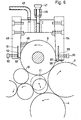
- FIG. 6 differs from FIG. 5 in that the adjustment is carried out manually by means of adjusting screws 47 which are arranged in a fixed crossmember 48. By turning the adjusting screw 47, the ink metering device can be adjusted relative to the ink cylinder 8 in the manner described.
- zone-regulating screws 50 are provided, which act on a tongue 52 formed by a longitudinal slot 51.
- the amount of paint could also be individually regulated in zones, a tear-off edge 53 being provided in the direction of rotation, at the end of the tongue, which prevents paint from collecting and dripping off.
- a support plate 54 is also provided, in which a similar tongue 55 can be adjusted via adjusting screws 56.
- a drip edge 57 is provided on the tongue 55, from which paint can drip into a groove 58.
- a turnbuckle 61 is provided in the upper part thereof, which regulates the angular position of the two plates via a threaded spindle 62 to each other.
- the elastic spacer plate 63 forms the fulcrum and at the same time serves to mount the ink metering device via the bearing bolts 64, which are fastened on both sides in the machine frames.
- the bridge 67 serves as a fulcrum for the metering plate 68.
- the screws 69 are rotated in such a way that the metering body 70 also circular cross section is made more or less to the outer surface of the ink cylinder 8.
- Bearing bolts 71 fastened in the side frames prevent the ink metering device from rotating.
- the opposite support plate 72 is provided with a plurality of sliding shoes 73, between which the ink on the lateral surface of the ink cylinder 8 can be returned to the ink supply 46.
- the cross section of the sliding shoes is acute as viewed in the direction of arrow A, as drawn.
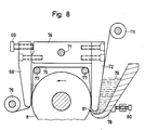
- the embodiment according to FIG. 8 differs from the embodiment 7a in that the bearing pins 71 engage directly in the bridge 74.
- a film 75 is provided in this embodiment, which can be wound on rollers 76. Only one of the two rolls, preferably the roll for winding up the soiled film, has to be rotated a little further and immediately there is again a new film section in the area of the metering surfaces.
- Deflection rollers 77 are provided within the ink metering device, which prevent the film from being placed on the ink cylinder 8.
- the paint is supplied via a separate channel 78 in which the supply of fresh paint 79 is located.
- the channel can be adjusted in the direction of the lateral surface of the ink cylinder 8 via the adjusting screw 80.
- the color of the ink cylinder 8 is then pre-metered between its outer surface and the film in the region of the support plate 72 by the rotary movement of the ink cylinder and the color conveyed is made more uniform in the region of the metering plate.
- the amount of paint supplied to the plate cylinder can be very finely regulated using the screws 69.
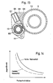
- FIG. 9 and 10 differ from FIG. 8 in that the scraper bodies 82 and 83 are concave and are supported on bolts 84.
- the adjusting screws 85 between the two arms 86 and 87 By turning the adjusting screws 85 between the two arms 86 and 87, the convex shape of the doctor body 82, 83 can be changed somewhat, so that this also enables a sensitive regulation of the color supplied.
- the feed of the. Color 88 takes place in the example of FIG. 9 via a shell 89, which can also be adjusted with respect to the ink cylinder 8 by means of an adjusting screw 80.
- the paint connection 90 is attached to a distributor bar 91 with paint and 92.
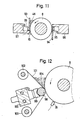
- a metering plate 93 and a support plate 94 are also assigned to the ink cylinder 8. Both are supported on pistons 95, which are pressurized by pressure medium, on fixedly mounted cross members 96, 97. Due to the exact opposite arrangement of the pressurized medium provided in zones. Pistons 95, the two opposite pistons can be connected in parallel via the pressure medium supply line, so that the mutual pressure is absolutely the same and thus cancels, so that no one-sided forces act on the ink cylinder 8.
- the surface doctor blades 94 and 93 are designed to be flexible.
- the pressure medium cylinder pairs 95 which are uniformly distributed and evenly distributed several times over the width, are subjected to the same pressure, so that the same color gap appears along the width, regardless of local shape or position errors. This version is particularly suitable for relatively wide machines.
- the exemplary embodiment according to FIG. 12 shows a cylindrical scraper body 98, which is supported on pistons 99, which are acted upon by pressure medium, on a fixed crossmember 100.
- the scraper body 98 is driven by a drive (not shown), the speed per unit of time, regardless of the machine speed, being chosen to be very low (a few revolutions per hour).
- the elastic roller-wide film 101 is also driven at exactly this speed, which in the exemplary embodiment shown is wound up again on a winding-up roller 103 by an unwinding roller 102 via the doctor body 98.
- An endlessly circulating film can also be used in the same way.
- the ink supply 104 is located between the upper leg of the film 101 and the outer surface of the ink cylinder 8. In this embodiment, dirt particles or dried-up paint residues cannot get stuck, so that an exact regulation of the amount of paint is possible.
- the embodiment according to FIG. 13 differs in that a color knife 105 which is tangential to the ink cylinder 8 is provided and is attached to a crossmember 106 which can hold coolant in a chamber 107 for cooling the ink supply 108.
- a pressure hose 109 is provided, which is supported in a pipe segment 110. Both the pipe segment 110 with the pressure hose 109 and the traverse 106 with the color knife 105 can be pivoted away via the pivot point 111. If a pressure medium is introduced into the pressure hose 109 in the swiveled-in position, it bulges more or less outwards and presses the ink knife 105 against the outer surface of the ink cylinder 8. This can be used to sensitively regulate the color gap and thus the amount of paint supplied.
- a coolant 112 can also be introduced into the ink cylinder 8 in this exemplary embodiment.
- the color knife 105 can also be designed as a hard film which is fastened to the fixed bearing 106 and is supported via the hose 109 filled with pressure medium. This has the advantage that if the film is damaged or worn, an easy replacement of the same is possible. B. can be done by gluing.
- Fig. 14 shows a diagram in which the Ver Relationships between the ink layer thickness and the specific contact pressure with different viscosity of the ink are reproduced. It can be clearly seen here that the color layer thickness on the ink cylinder 8 is smaller for a paint with low viscosity and the same contact pressure. The cooling provided allows the viscosity of the paint to be kept constant within narrow limits.
Landscapes
- Inking, Control Or Cleaning Of Printing Machines (AREA)
- Rotary Presses (AREA)
- Coating Apparatus (AREA)
Claims (13)
Applications Claiming Priority (2)
| Application Number | Priority Date | Filing Date | Title |
|---|---|---|---|
| DE3217569A DE3217569C2 (de) | 1982-05-11 | 1982-05-11 | Verfahren und Vorrichtung zum Dosieren der Farbe bei Offsetdruckmaschinen |
| DE3217569 | 1982-05-11 |
Publications (2)
| Publication Number | Publication Date |
|---|---|
| EP0093879A1 EP0093879A1 (fr) | 1983-11-16 |
| EP0093879B1 true EP0093879B1 (fr) | 1986-09-10 |
Family
ID=6163214
Family Applications (1)
| Application Number | Title | Priority Date | Filing Date |
|---|---|---|---|
| EP83103480A Expired EP0093879B1 (fr) | 1982-05-11 | 1983-04-11 | Procédé et dispositif de dosage d'encre dans les rotatives offset |
Country Status (7)
| Country | Link |
|---|---|
| US (2) | US4699055A (fr) |
| EP (1) | EP0093879B1 (fr) |
| JP (3) | JPS5952657A (fr) |
| AT (1) | AT388706B (fr) |
| CA (1) | CA1219168A (fr) |
| DE (1) | DE3217569C2 (fr) |
| ES (2) | ES522257A0 (fr) |
Families Citing this family (16)
| Publication number | Priority date | Publication date | Assignee | Title |
|---|---|---|---|---|
| DE3324893C1 (de) * | 1983-07-09 | 1985-03-14 | Heidelberger Druckmaschinen Ag, 6900 Heidelberg | Vorrichtung zum Dosieren der Farbe bei Offsetdruckmaschinen |
| JPH0629315B2 (ja) * | 1985-05-29 | 1994-04-20 | ユニチカ株式会社 | 微小球状樹脂組成物及びその製造法 |
| DE3526308A1 (de) * | 1985-07-23 | 1987-02-05 | Wifag Maschf | Vorrichtung zum feindosieren eines fluessigkeitsfilms auf einer rotierenden walze einer druckmaschine |
| FR2598427B1 (fr) * | 1986-05-09 | 1988-06-03 | Holden Europ Sa | Composition a base d'une resine phenolique et d'une resine epoxydique pour revetements, notamment metallises |
| DE3628464C1 (de) * | 1986-08-21 | 1988-03-10 | Koenig & Bauer Ag | Druckfarbenzufuhr in einem Farbwerk einer Bogenrotationsdruckmaschine |
| DE3714936A1 (de) * | 1987-05-05 | 1988-12-08 | Wifag Maschf | Farbwerk fuer eine druckmaschine |
| WO1989005321A1 (fr) * | 1987-12-12 | 1989-06-15 | Nippon Steel Chemical Co., Ltd. | Resine d'hydrocarbures modifiee par un epoxy |
| JP2542748B2 (ja) * | 1991-03-28 | 1996-10-09 | コニシ株式会社 | 接着剤組成物 |
| DE4239793A1 (fr) * | 1992-01-03 | 1993-07-08 | Noelle Gmbh | |
| US5823110A (en) * | 1993-07-20 | 1998-10-20 | I Mar Planning Inc. | Inking arrangement for printing presses |
| DE4413731C2 (de) * | 1994-04-20 | 1998-07-02 | Heidelberger Druckmasch Ag | Verfahren zur Steuerung der Temperatur der Druckfarbe in einer Druckmaschine |
| CN1172797C (zh) | 1996-10-25 | 2004-10-27 | 柯尼格及包尔公开股份有限公司 | 墨斗 |
| DE19912881C2 (de) * | 1999-03-23 | 2001-02-22 | Technotrans Ag | Vorrichtung zur Versorgung eines Farbspeichers einer Druckmaschine mit Farbe |
| DE10058550A1 (de) * | 2000-11-24 | 2002-05-29 | Heidelberger Druckmasch Ag | Verfahren zur Regelung des Farb-zu-Feuchtmittelgleichgewichts in einer Rotations-Offsetdruckmaschine |
| US7546802B2 (en) * | 2003-07-28 | 2009-06-16 | Goss International Americas, Inc. | Fluid supply device for a printing machine |
| DE102022101244A1 (de) | 2022-01-20 | 2023-07-20 | Koenig & Bauer Ag | Verfahren zur Kalibrierung von Farbdosierelementen |
Citations (1)
| Publication number | Priority date | Publication date | Assignee | Title |
|---|---|---|---|---|
| EP0078444A1 (fr) * | 1981-10-31 | 1983-05-11 | Heidelberger Druckmaschinen Aktiengesellschaft | Dispositif d'encrage pour machines à imprimer offset |
Family Cites Families (33)
| Publication number | Priority date | Publication date | Assignee | Title |
|---|---|---|---|---|
| GB168933A (en) * | 1920-04-14 | 1921-09-14 | John Hooper Butler | Improvements relating to inking mechanism for printing machines |
| US2359640A (en) * | 1942-02-20 | 1944-10-03 | H H Heinrich Inc | Inking mechanism for printing presses |
| US2377110A (en) * | 1943-09-15 | 1945-05-29 | Rice Barton Corp | Printing roll inking device |
| US2435452A (en) * | 1945-05-05 | 1948-02-03 | Albert W Linn | Color inker for cylinder presses |
| US2645176A (en) * | 1950-03-14 | 1953-07-14 | Bennett B Perry | Ink fountain for printing presses |
| US2823607A (en) * | 1956-07-13 | 1958-02-18 | Waynesboro Publishing Corp | Portable color ink fountain |
| DE1269138B (de) * | 1961-02-23 | 1968-05-30 | Koppers Co Inc | Farbkasten fuer eine Druckmaschine mit einem biegsamen Farbmesser |
| US3141408A (en) * | 1961-11-21 | 1964-07-21 | Interchem Corp | High speed printing with super-fast inks |
| GB1230020A (fr) * | 1967-06-30 | 1971-04-28 | ||
| US3585932A (en) * | 1968-06-07 | 1971-06-22 | Wallace H Granger | Automatic inking system for rotary newspaper printing press |
| GB1267947A (en) * | 1969-10-30 | 1972-03-22 | Metal Box Co Ltd | Improvements in inking apparatus for printing machines |
| AT310547B (de) * | 1970-02-17 | 1973-10-10 | Feldmuehle Anlagen Prod | Vorrichtung zum Streichen von bahnförmigem Material |
| US3747524A (en) * | 1971-09-21 | 1973-07-24 | Harris Intertype Corp | Ink fountain key control system |
| DE2214721B1 (de) * | 1972-03-25 | 1973-06-14 | Heidelberger Druckmaschinen Ag, 6900 Heidelberg | Verfahren und vorrichtung zum selbsttaetigen ausregeln von schwankungen der farb- und feuchtfluessigkeitsfuehrung an offsetmaschinen |
| CA1019637A (en) * | 1972-05-09 | 1977-10-25 | Dahlgren Manufacturing Company | Method and apparatus for inking printing plates |
| US3820459A (en) * | 1972-06-15 | 1974-06-28 | F Paul | Offset press fountain keys |
| DE2247351C3 (de) * | 1972-09-27 | 1980-04-10 | European Rotogravure Association, 8000 Muenchen | Verfahren und Vorrichtung zur lichtelektrischen Messung und Einregelung einer Farbschicht auf dem Formzylinder einer Rotations-Tiefdruckmaschine |
| US3835777A (en) * | 1973-01-16 | 1974-09-17 | Harris Intertype Corp | Ink density control system |
| DE2438668B2 (de) * | 1973-08-28 | 1979-03-01 | Texogesa S.A., Genf (Schweiz) | Farbwerk für Druckmaschinen |
| US3921525A (en) * | 1973-10-30 | 1975-11-25 | American Bank Note Co | Adjustable and retractable ink supply mechanism for printing press |
| JPS5724217B2 (fr) * | 1974-06-27 | 1982-05-22 | ||
| JPS5151283U (fr) * | 1974-10-09 | 1976-04-19 | ||
| DE2555993C3 (de) * | 1975-12-12 | 1980-11-06 | Koenig & Bauer Ag, 8700 Wuerzburg | Farbkasten eines Farbwerkes |
| DE2658380B2 (de) * | 1976-12-23 | 1979-02-08 | Grapho-Metronic Mess- Und Regeltechnik Gmbh & Co Kg, 8000 Muenchen | Farbwalze für Druckmaschinen |
| SE433829B (sv) * | 1977-03-21 | 1984-06-18 | Dahlgren Harold P | Forfarande och tryckfergsutmetningsapparat for utmetning av tryckferg |
| US4157682A (en) * | 1977-08-01 | 1979-06-12 | Am International, Inc. | Ink and moisture control system with run-length compensation |
| JPS5828743B2 (ja) * | 1977-09-02 | 1983-06-17 | 株式会社日立製作所 | 高電圧用サイリスタバルブ |
| JPS557453A (en) * | 1978-07-03 | 1980-01-19 | Mitsubishi Heavy Ind Ltd | Ink feeder |
| DD139113A1 (de) * | 1978-10-19 | 1979-12-12 | Hermann Doebler | Farbwerk |
| DE2923678C2 (de) * | 1979-06-12 | 1982-02-18 | Heidelberger Druckmaschinen Ag, 6900 Heidelberg | Farbkasten mit einzelnen, jeweils über die gesamte Zonenbreite reichenden Farbdosiereinrichtungen |
| US4244292A (en) * | 1979-10-17 | 1981-01-13 | Sun Chemical Corporation | Inker apparatus |
| DE3040455A1 (de) * | 1980-05-27 | 1981-12-03 | Deutsche ICI GmbH, 2000 Hamburg | Einrichtung zur farbdosierung in einer druckmaschine, insbesondere einer offset-bogenmaschine |
| DE3101300C2 (de) * | 1980-12-01 | 1983-03-17 | Windmöller & Hölscher, 4540 Lengerich | Rakelvorrichtung |
-
1982
- 1982-05-11 DE DE3217569A patent/DE3217569C2/de not_active Expired
-
1983
- 1983-04-01 AT AT0117783A patent/AT388706B/de not_active IP Right Cessation
- 1983-04-11 EP EP83103480A patent/EP0093879B1/fr not_active Expired
- 1983-04-20 CA CA000426314A patent/CA1219168A/fr not_active Expired
- 1983-05-09 JP JP58079487A patent/JPS5952657A/ja active Pending
- 1983-05-09 JP JP58079485A patent/JPS58203059A/ja active Pending
- 1983-05-09 JP JP58079486A patent/JPS5952656A/ja active Pending
- 1983-05-10 ES ES522257A patent/ES522257A0/es active Granted
- 1983-05-10 ES ES522258A patent/ES522258A0/es active Granted
-
1985
- 1985-12-19 US US06/810,837 patent/US4699055A/en not_active Expired - Fee Related
-
1990
- 1990-02-26 US US07/485,816 patent/US5020432A/en not_active Expired - Lifetime
Patent Citations (1)
| Publication number | Priority date | Publication date | Assignee | Title |
|---|---|---|---|---|
| EP0078444A1 (fr) * | 1981-10-31 | 1983-05-11 | Heidelberger Druckmaschinen Aktiengesellschaft | Dispositif d'encrage pour machines à imprimer offset |
Also Published As
| Publication number | Publication date |
|---|---|
| US5020432A (en) | 1991-06-04 |
| ES8402205A1 (es) | 1984-02-01 |
| ATA117783A (de) | 1989-01-15 |
| ES8402206A1 (es) | 1984-02-01 |
| EP0093879A1 (fr) | 1983-11-16 |
| JPS58203059A (ja) | 1983-11-26 |
| AT388706B (de) | 1989-08-25 |
| ES522258A0 (es) | 1984-02-01 |
| JPS5952657A (ja) | 1984-03-27 |
| CA1219168A (fr) | 1987-03-17 |
| ES522257A0 (es) | 1984-02-01 |
| US4699055A (en) | 1987-10-13 |
| DE3217569C2 (de) | 1985-11-28 |
| JPS5952656A (ja) | 1984-03-27 |
| DE3217569A1 (de) | 1983-11-17 |
Similar Documents
| Publication | Publication Date | Title |
|---|---|---|
| EP0093879B1 (fr) | Procédé et dispositif de dosage d'encre dans les rotatives offset | |
| EP0159474B1 (fr) | Dispositif d'encrage pour machines d'impression offset | |
| DE3800570C2 (fr) | ||
| DE102017211843B4 (de) | Druckmaschine mit einem nach dem Inkjet-Verfahren arbeitenden Druckwerk sowie Verfahren zur Vorbereitung von Bedruckstoff | |
| DE1176674B (de) | Farbwerk fuer Rotationsdruckmaschinen | |
| CH672096A5 (fr) | ||
| DD143059A5 (de) | Druckvorrichtung sowie farbwerk fuer eine druckvorrichtung | |
| DE8413874U1 (de) | Vorrichtung zum Befeuchten an lithographischen Druckpressen | |
| DE19902005A1 (de) | Offsetdruckpresse mit variabler Teilung | |
| EP0305796B1 (fr) | Dispositif de mouillage pour machines d'impression en offset | |
| JPS60242065A (ja) | 輪転印刷機の版胴の版盤にインキを着けるインキ装置 | |
| EP0131186A2 (fr) | Dispositif de dosage de l'encre dans les machines à imprimer offset | |
| DE69117844T2 (de) | Verbessertes Drucksystem ohne Farbmesser zum lithographischem Drucken ohne Farbmesser | |
| DE2812998A1 (de) | Verfahren und vorrichtung zum dosieren einer fluessigkeit auf einer walze | |
| AT397635B (de) | Dosiervorrichtung eines farbwerkes einer druckmaschine | |
| DE4138730C1 (fr) | ||
| DE2913825C2 (fr) | ||
| DD202663A5 (de) | Farbwerk fuer eine lithographische druckmaschine | |
| DE3644982C2 (fr) | ||
| DE2405859A1 (de) | Verfahren fuer das einstellen sowie anund abstellen von walzen in druckmaschinen und einrichtung zur durchfuehrung des verfahrens | |
| DE68911263T2 (de) | Feuchtvorrichtung mit schwingender Auftragswalze. | |
| DE102004006231B3 (de) | Verfahren zum Transportieren von Feuchtmittel von einer ersten Walze an die Oberfläche eines Formzylinders einer Druckmaschine | |
| DE8224875U1 (de) | Farbwerk für Offsetdruckmaschinen | |
| DE3102043A1 (de) | "anordnung zur dosierung des feuchtmittels fuer offset-druckmaschinen" | |
| DE10325185B4 (de) | Verfahren zum Betrieb eines Druckwerks einer Druckmaschine in Abhängigkeit von der Farbtemperatur sowie nach dem Verfahren arbeitende Druckmaschinensteuerung |
Legal Events
| Date | Code | Title | Description |
|---|---|---|---|
| PUAI | Public reference made under article 153(3) epc to a published international application that has entered the european phase |
Free format text: ORIGINAL CODE: 0009012 |
|
| 17P | Request for examination filed |
Effective date: 19830411 |
|
| AK | Designated contracting states |
Designated state(s): BE CH FR GB IT LI NL SE |
|
| GRAA | (expected) grant |
Free format text: ORIGINAL CODE: 0009210 |
|
| AK | Designated contracting states |
Kind code of ref document: B1 Designated state(s): BE CH FR GB IT LI NL SE |
|
| ET | Fr: translation filed | ||
| ITF | It: translation for a ep patent filed | ||
| PGFP | Annual fee paid to national office [announced via postgrant information from national office to epo] |
Ref country code: NL Payment date: 19870430 Year of fee payment: 5 |
|
| PLBE | No opposition filed within time limit |
Free format text: ORIGINAL CODE: 0009261 |
|
| STAA | Information on the status of an ep patent application or granted ep patent |
Free format text: STATUS: NO OPPOSITION FILED WITHIN TIME LIMIT |
|
| 26N | No opposition filed | ||
| PG25 | Lapsed in a contracting state [announced via postgrant information from national office to epo] |
Ref country code: BE Effective date: 19890430 |
|
| BERE | Be: lapsed |
Owner name: HEIDELBERGER DRUCKMASCHINEN A.G. Effective date: 19890430 |
|
| PG25 | Lapsed in a contracting state [announced via postgrant information from national office to epo] |
Ref country code: NL Effective date: 19891101 |
|
| NLV4 | Nl: lapsed or anulled due to non-payment of the annual fee | ||
| PGFP | Annual fee paid to national office [announced via postgrant information from national office to epo] |
Ref country code: SE Payment date: 19900420 Year of fee payment: 8 |
|
| PGFP | Annual fee paid to national office [announced via postgrant information from national office to epo] |
Ref country code: GB Payment date: 19910325 Year of fee payment: 9 |
|
| PGFP | Annual fee paid to national office [announced via postgrant information from national office to epo] |
Ref country code: FR Payment date: 19910409 Year of fee payment: 9 |
|
| PG25 | Lapsed in a contracting state [announced via postgrant information from national office to epo] |
Ref country code: SE Effective date: 19910412 |
|
| ITTA | It: last paid annual fee | ||
| PGFP | Annual fee paid to national office [announced via postgrant information from national office to epo] |
Ref country code: CH Payment date: 19910521 Year of fee payment: 9 |
|
| PG25 | Lapsed in a contracting state [announced via postgrant information from national office to epo] |
Ref country code: GB Effective date: 19920411 |
|
| PG25 | Lapsed in a contracting state [announced via postgrant information from national office to epo] |
Ref country code: LI Effective date: 19920430 Ref country code: CH Effective date: 19920430 |
|
| GBPC | Gb: european patent ceased through non-payment of renewal fee | ||
| PG25 | Lapsed in a contracting state [announced via postgrant information from national office to epo] |
Ref country code: FR Effective date: 19921230 |
|
| REG | Reference to a national code |
Ref country code: CH Ref legal event code: PL |
|
| REG | Reference to a national code |
Ref country code: FR Ref legal event code: ST |
|
| EUG | Se: european patent has lapsed |
Ref document number: 83103480.6 Effective date: 19911108 |