EP0093973A2 - Support adaptable à une surface plate et verticale d'un chaudron - Google Patents
Support adaptable à une surface plate et verticale d'un chaudron Download PDFInfo
- Publication number
- EP0093973A2 EP0093973A2 EP83104186A EP83104186A EP0093973A2 EP 0093973 A2 EP0093973 A2 EP 0093973A2 EP 83104186 A EP83104186 A EP 83104186A EP 83104186 A EP83104186 A EP 83104186A EP 0093973 A2 EP0093973 A2 EP 0093973A2
- Authority
- EP
- European Patent Office
- Prior art keywords
- plate
- rod means
- width
- hole
- appliance
- Prior art date
- Legal status (The legal status is an assumption and is not a legal conclusion. Google has not performed a legal analysis and makes no representation as to the accuracy of the status listed.)
- Withdrawn
Links
- 230000001788 irregular Effects 0.000 claims abstract description 6
- 238000010411 cooking Methods 0.000 description 6
- 239000002184 metal Substances 0.000 description 6
- 229910052751 metal Inorganic materials 0.000 description 6
- 239000003292 glue Substances 0.000 description 3
- XEEYBQQBJWHFJM-UHFFFAOYSA-N Iron Chemical compound [Fe] XEEYBQQBJWHFJM-UHFFFAOYSA-N 0.000 description 2
- 238000005219 brazing Methods 0.000 description 2
- 238000003466 welding Methods 0.000 description 2
- 229910001369 Brass Inorganic materials 0.000 description 1
- 229910000831 Steel Inorganic materials 0.000 description 1
- 238000013019 agitation Methods 0.000 description 1
- 239000004411 aluminium Substances 0.000 description 1
- 229910052782 aluminium Inorganic materials 0.000 description 1
- XAGFODPZIPBFFR-UHFFFAOYSA-N aluminium Chemical compound [Al] XAGFODPZIPBFFR-UHFFFAOYSA-N 0.000 description 1
- 238000009835 boiling Methods 0.000 description 1
- 239000010951 brass Substances 0.000 description 1
- 229910052742 iron Inorganic materials 0.000 description 1
- 239000000463 material Substances 0.000 description 1
- 238000000034 method Methods 0.000 description 1
- 239000010959 steel Substances 0.000 description 1
- 238000003756 stirring Methods 0.000 description 1
- XLYOFNOQVPJJNP-UHFFFAOYSA-N water Substances O XLYOFNOQVPJJNP-UHFFFAOYSA-N 0.000 description 1
- 239000002023 wood Substances 0.000 description 1
Images
Classifications
-
- F—MECHANICAL ENGINEERING; LIGHTING; HEATING; WEAPONS; BLASTING
- F24—HEATING; RANGES; VENTILATING
- F24C—DOMESTIC STOVES OR RANGES ; DETAILS OF DOMESTIC STOVES OR RANGES, OF GENERAL APPLICATION
- F24C15/00—Details
- F24C15/08—Foundations or supports plates; Legs or pillars; Casings; Wheels
- F24C15/086—Adjustable legs or pillars
Definitions
- This invention relates to a bracket adaptable for mounting to a flat, vertical surface of an appliance, and further adapted to accomodate a threaded elongated means for leveling said appliance upon an irregular surface, especially to an apparatus for attaching to a conventional outdoor appliance to provide a means for raising said appliance to be supported by adjustable legs in order that the appliance be leveled when placed on an irregular surface, and particularly to a stove jack apparatus.
- a rectangular plate having substantially equal length and width and a thickness from about one-eighth to one-tenth of said width, said plate having securely attached to one surface thereof an elongated rod means, said rod means located equidistant from each lateral edge of said plate and said rod means having the lower end thereof aligned with the lower edge of said plate, whereby the central axis of said rod means is perpendicular to said lower edge of said plate and parallel to said surface; said rod means having a threaded hole extending through its entire length and concentric with said central axis, the length of said rod means being about one-half the length of said plate and the maximum width of said rod means being about one-third of the width of said plate; said plate having at least one hole located approximately equidistant from each lateral edge of said plate, said hole having a central axis perpendicular to the surface of said plate.
- said hole in said plate is located approximately equidistant between the top end of said rod means and the upper edge of said plate.
- said plate has two additional holes, each said hole located approximately equidistant between the upper edge and lower edge of said plate.
- said rod means is rectangular of a length of about one-half the height of said plate and a width of about one-third the width of said plate. Especially the height of said plate is about 35 mm, the width of said plate is about 38 mm, and the thickness of said plate is about 3,2 mm, the height of said rod means is about 19 mm and the width of said rod means is about 13 mm.
- the invention comprises also a kit having a plurality of brackets and a plurality of elongated threaded headless bolts adapted for threading into said threaded hole in said rod means, a plurality of screws of a diameter sufficient to fit through said hole in said plate, and a plurality of speed nuts.
- the kit comprises four each of said brackets and said threaded elongated headless bolts.
- the present invention provides a bracket adaptable for mounting to a flat vertical surface on an appliance, such as an outdoor cooking stove, which bracket is adapted to accomodate a threaded elongated means, such as an elongated headless bolt, which is used to adjustably raise and level the appliance. It is preferred that the brackets be combined into kits of four each of a bracket and elongated headless threaded bolt, and a plurality of conventional sheet metal screws and speed nuts so that a bracket may be mounted at each corner of a conventional outdoor stove. Each of the threaded elongated bolts may then be adjusted to level the stove on an irregular surface.
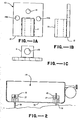
- FIGURES 1A, 1B and 1C there are shown front and side elevations and a plan, respectively, of a bracket means for attachment of the jacking and leveling apparatus to a stove according to the present invention.
- FIGURE 2 there is shown the stove jack apparatus according to the present invention attached to a conventional outdoor cooking stove.
- the bracket comprises a rectangular plate 10 having its height substantially equal to its width and a thickness from about 1/8 to 1/10 of said width.
- said height is about 35 mm
- said width is about 38 mm
- said thickness is from about 3,2 mm.
- Plate 10 has securely attached to one surface thereof elongated rod means 11 located equidistant from the vertical edges of plate 10 and aligned with the lower edge 12 of plate 10.
- Rod means 11 has a central axis perpendicular to edge 12. As shown, rod means 11 is cylindrical in form, however it may be in other geometric shapes such as a rectangular rod, hexagonal rod, etc. Rod means 11 may be securely attached to plate 10 by welding, glue, brazing, and the like. Referring to FIGURE 1C, rod means 11 has a vertical centrally located threaded hole 13 extending through the entire length of rod 11 and having an axis concentric with the central axis of rod 11.
- the length of rod 11 is about one-half the height of plate 10 and the maximum diameter of rod 11 is about one-third the width of plate 10.
- the height of rod 11 is about 19 mm and the width is about 13 mm.
- Plate 10 has a hole 14 located approximately equidistant from the top end of rod 11 and the upper edge of plate 10. Hole 14 is located equidistant from each side edge of plate 10 and hole 14 has its central axis perpendicular to the surface of plate 10.
- Plate 10 also has holes 14A located approximately equidistant between the upper and lower edges of plate 10 and approximately equidistant between the respective side edge of plate 10 and outer edge of rod 11. It is necessary that plate 10 has at least one hole 14, preferably located approximately equidistant from each lateral edge of plate 10, such hole having a central axis perpendicular to the surface of plate 10.
- additional holes 14A allow 10 to be adaptable for mounting onto substantially all conventional outdcor cooking stoves. If a conventional stove (Coleman) is used, the lower edge of rod means 11 will be flush to flange 18 as shown in FIGURE 2. In such a case, only a single hole 14 is necessary in order to securely fix the orientation of 10 on the stove.
- flange 18 may not be present and at least two mounting holes are necessary in order to fix the orientation of 10 on the stove.
- holes 14A it is necessary that holes 14A be utilized to mount 10 to the stove.
- the versatility of 10 is therefore increased if holes 14 and 14A are all present so that they may be utilized as needed according to the particular stove.
- Holes 14 and 14A may be threaded, but are preferably unthreaded and of a diameter sufficient to accomodate a conventional sheet metal screw.
- Plate 10 and rod 11 may be made of metal, such as iron, steel, aluminium, brass and the like and may be joined by heliarcing, welding, brazing or other suitable metal to metal bonding means.
- plate 10 and rod 11 may be made of any hard material, such as plastic, fiberglas, and the like, in which case they may be joined by glue, particularly thermo-setting glue, which provides a strong permanent bond.
- FIGURE 2 there is shown a pair of brackets attached to a conventional stove (Coleman).
- the brackets 15 are attached to the vertical surface of the stove 16 by conventional sheet metal screws 17.
- the brackets are specifically designed so that the lower edge of rod means 11 is flush to flange 18 of the stove.
- Elongated threaded headless bolts 19 are threaded into the holes 13 of the brackets and may be adjusted up or down in order to level the stove.
Landscapes
- Engineering & Computer Science (AREA)
- Chemical & Material Sciences (AREA)
- Combustion & Propulsion (AREA)
- Mechanical Engineering (AREA)
- General Engineering & Computer Science (AREA)
- Baking, Grill, Roasting (AREA)
- Electric Stoves And Ranges (AREA)
Applications Claiming Priority (2)
| Application Number | Priority Date | Filing Date | Title |
|---|---|---|---|
| US37659582A | 1982-05-10 | 1982-05-10 | |
| US376595 | 1982-05-10 |
Publications (2)
| Publication Number | Publication Date |
|---|---|
| EP0093973A2 true EP0093973A2 (fr) | 1983-11-16 |
| EP0093973A3 EP0093973A3 (fr) | 1984-04-04 |
Family
ID=23485651
Family Applications (1)
| Application Number | Title | Priority Date | Filing Date |
|---|---|---|---|
| EP83104186A Withdrawn EP0093973A3 (fr) | 1982-05-10 | 1983-04-28 | Support adaptable à une surface plate et verticale d'un chaudron |
Country Status (1)
| Country | Link |
|---|---|
| EP (1) | EP0093973A3 (fr) |
Cited By (1)
| Publication number | Priority date | Publication date | Assignee | Title |
|---|---|---|---|---|
| US6790033B2 (en) * | 2001-09-06 | 2004-09-14 | Fleming Sales Company, Inc. | Outdoor fireplace with cascading waterfall fire screen |
Family Cites Families (3)
| Publication number | Priority date | Publication date | Assignee | Title |
|---|---|---|---|---|
| DE1649034U (de) * | 1952-11-07 | 1953-01-08 | W B Banning Kommandit Ges | Befestigungseinrichtung fuer herdsaeulen. |
| DE2109782A1 (de) * | 1971-03-02 | 1972-09-07 | Siemens Elektrogeraete Gmbh | Hausgerät, insbesondere Herd |
| US3924602A (en) * | 1974-08-26 | 1975-12-09 | Raymond Lee Organization Inc | Stove top with leveling means |
-
1983
- 1983-04-28 EP EP83104186A patent/EP0093973A3/fr not_active Withdrawn
Cited By (1)
| Publication number | Priority date | Publication date | Assignee | Title |
|---|---|---|---|---|
| US6790033B2 (en) * | 2001-09-06 | 2004-09-14 | Fleming Sales Company, Inc. | Outdoor fireplace with cascading waterfall fire screen |
Also Published As
| Publication number | Publication date |
|---|---|
| EP0093973A3 (fr) | 1984-04-04 |
Similar Documents
| Publication | Publication Date | Title |
|---|---|---|
| US6427966B1 (en) | Support base for household appliances | |
| US4363956A (en) | Cooking panel unit for installation in work surface | |
| US4607608A (en) | Campfire cooking grill | |
| US2264082A (en) | Support | |
| US2884649A (en) | Stainless sheet metal work surfaces | |
| US5169219A (en) | System for installing cabinetry | |
| EP0093973A2 (fr) | Support adaptable à une surface plate et verticale d'un chaudron | |
| US1539112A (en) | Supporting-leg construction | |
| US11339558B1 (en) | Sink mounting apparatus | |
| US3924602A (en) | Stove top with leveling means | |
| US5871191A (en) | Adjustable mounting bracket | |
| US2472685A (en) | Kitchen cabinet structure | |
| US7137604B2 (en) | Adjustable furnace legs | |
| JPS646435A (en) | Construction method for mounting alc vertical wall panel | |
| CN218565506U (zh) | 一种具有限位功能的电磁炉 | |
| JPS5833119Y2 (ja) | 水槽 | |
| JPS6128158Y2 (fr) | ||
| WO2021188109A1 (fr) | Appareil de montage d'évier | |
| CN214402630U (zh) | 一种墙砖支撑装置 | |
| JPH0248531Y2 (fr) | ||
| JPH0473048B2 (fr) | ||
| JPH0240806Y2 (fr) | ||
| KR960007172Y1 (ko) | 유리탁자용 다리 | |
| KR850000364Y1 (ko) | 조립식 렌지장치 | |
| JPS627784Y2 (fr) |
Legal Events
| Date | Code | Title | Description |
|---|---|---|---|
| PUAI | Public reference made under article 153(3) epc to a published international application that has entered the european phase |
Free format text: ORIGINAL CODE: 0009012 |
|
| AK | Designated contracting states |
Designated state(s): AT BE CH DE FR GB IT LI LU NL SE |
|
| PUAL | Search report despatched |
Free format text: ORIGINAL CODE: 0009013 |
|
| AK | Designated contracting states |
Designated state(s): AT BE CH DE FR GB IT LI LU NL SE |
|
| STAA | Information on the status of an ep patent application or granted ep patent |
Free format text: STATUS: THE APPLICATION IS DEEMED TO BE WITHDRAWN |
|
| 18D | Application deemed to be withdrawn |
Effective date: 19841205 |