EP0094061B1 - Apparatus for dissolution of pulp - Google Patents
Apparatus for dissolution of pulp Download PDFInfo
- Publication number
- EP0094061B1 EP0094061B1 EP83104497A EP83104497A EP0094061B1 EP 0094061 B1 EP0094061 B1 EP 0094061B1 EP 83104497 A EP83104497 A EP 83104497A EP 83104497 A EP83104497 A EP 83104497A EP 0094061 B1 EP0094061 B1 EP 0094061B1
- Authority
- EP
- European Patent Office
- Prior art keywords
- pulp
- water
- diluting apparatus
- cylindrical vessel
- rotary shaft
- Prior art date
- Legal status (The legal status is an assumption and is not a legal conclusion. Google has not performed a legal analysis and makes no representation as to the accuracy of the status listed.)
- Expired
Links
- 238000004090 dissolution Methods 0.000 title 1
- XLYOFNOQVPJJNP-UHFFFAOYSA-N water Substances O XLYOFNOQVPJJNP-UHFFFAOYSA-N 0.000 claims 19
- 238000007865 diluting Methods 0.000 claims 16
Images
Classifications
-
- D—TEXTILES; PAPER
- D21—PAPER-MAKING; PRODUCTION OF CELLULOSE
- D21F—PAPER-MAKING MACHINES; METHODS OF PRODUCING PAPER THEREON
- D21F1/00—Wet end of machines for making continuous webs of paper
- D21F1/0018—Devices for dispensing fibres in a fluid
-
- D—TEXTILES; PAPER
- D21—PAPER-MAKING; PRODUCTION OF CELLULOSE
- D21D—TREATMENT OF THE MATERIALS BEFORE PASSING TO THE PAPER-MAKING MACHINE
- D21D5/00—Purification of the pulp suspension by mechanical means; Apparatus therefor
- D21D5/28—Tanks for storing or agitating pulp
Definitions
- the present invention relates to a pulp diluting apparatus comprising a cylindrical vessel having a pulp inlet at the top portion thereof, a steady rest bearing mounted on the central bottom portion of said cylindrical vessel, a rotary shaft supported by said steady rest bearing and provided on the lower portion thereof with rotary rods having members depending therefrom, and an outlet provided in the lower portion of said cylindrical vessel for taking the pulp out of said vessel.
- this diluting apparatus has a disadvantage in that it gives rise to the adverse phenomenon that stirring cannot be effected because the high-density pulp is swollen into a mass and becomes heavy in weight.
- it has been adopted to provide the diluting apparatus with a special device for taking out the slurry and to pour a large quantity of water toward the vicinity of a pulp outlet.
- this adoption suffers fatal disadvantages in that, since the density of the pulp at a dilution portion is not uniform, desired pulp of uniform density cannot be taken out and in that the energy consumption for the dilution cannot be reduced.
- a circulating pump is provided outside the vessel having a suction pipe thereof connected to the outlet of the vessel and a feed pipe thereof communicating with the upper end of a channel extending through the rotary shaft.
- the lower end of this channel communicates with passages extending longitudinally through the rotary rods.
- the members which depend from the rotary rods are formed by radially and downwardly extending tubes communicating at one end with the passages in the rotary rods while the other end is formed as a nozzle.
- the circulating pump thus causes the pulp to be circulated from the outlet through the rotary shaft and the rotary rods to be finally expelled through the nozzle-like members thus causing a rotation of the rotary rods and the rotary shaft as a result of the recoil of the jet-like streams of pulp discharged from the nozzle-like members.
- an air supply pipe is connected to the circulating pump for the purpose of aeration of the pulp circulating in the external circuit no provision is made in the known apparatus for effectively diluting a high-density pulp to be stored within the cylindrical vessel to obtain a desired lower density pulp at the outlet.
- the present invention is characterized by the depending members being in the form of scraper plates, a water supply pipe disposed on the bottom portion of said cylindrical vessel for supplying water into said cylindrical vessel to thereby obtain diluted pulp at the outlet, a valve provided on said water supply pipe for controlling the amount of water to be supplied into said water supply pipe, a driving machine connected to said rotary shaft for rotating said rotary shaft being supported at its upper end by a bearing mounted on the center of a lid which covers the top portion of said cylindrical vessel, and a torque detector for detecting the torque of said driving machine and controlling said valve of said water supply pipe.
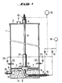
- Fig. 1 is a cross section showing the apparatus for the dilution of pulp according to the present invention.
- Denoted by 1 is a cylindrical pulp diluting vessel covered with a lid 2 having a pulp inlet 3.
- a rotary shaft 8 extending from above the central upper portion of the vessel toward the bottom of the vessel is held between a bearing 4 mounted on the lid and a steady rest bearing 5 to thereby prevent runout of the rotary shaft.
- a plurality of rotary rods 7 are arranged and provided with scraper plates 6.
- the rotary rod may be straightened out, it is preferably bent to have a convex portion formed in the rotating direction so that rotation may be made smoothly.
- the scraper plates may be fixed firmly to the rotary rods and, when swingably connected to the rotary rods, advantageously fulfill their function because resistance adjustment can automatically be effected.
- a water supply pipe 9 is connected to the lower portion of the vessel for pouring water for dilution into the vessel and is desirable to have its opening disposed at the center of the lower portion of the vessel so as to uniformly supply water. Since water is supplied from the lower portion of the vessel, as described .above, a current of water ascends and serves to push pulp upwardly.
- the vessel is provided on the lower portion thereof with an outlet 13 for diluted pulp slurry.
- a stirrer 24 is attached to the slurry outlet for taking the pulp slurry out of the vessel.
- the bottom portion 14 of the vessel is inclined downwardly toward the slurry outlet, thereby enhancing the effect of taking the pulp slurry out of the vessel.
- the scraper plates cause the diluted pulp to collect to the slurry outlet.
- a driving machine 10 for the rotary shaft 8 is provided with a torque detector 12 for detecting the torque of the driving machine, thereby controlling the opening and shutting of a valve 11 of the water supply pipe to adjust the amount of water for dilution.
- the apparatus for the dilution of pulp according to the present invention is constructed as described above. Therefore, pulp is urged to ascend by the water supplied from the lower portion of the vessel and, therefore, floats within the vessel. Dilution of a mass of swollen pulp begins at the contact region between the lower portion of the pulp and water, and is effected continuously.
- the load exerted on the rotary shaft varies in accordance with only the concentration of the pulp in the pulp slurry. According to the present invention, therefore, since the pulp concentration in the pulp slurry can be found by detecting the torque of the rotary shaft, control of the amount of water to be supplied from the lower portion of the vessel enables the pulp slurry having uniform concentration to be taken out of the vessel.
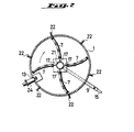
- the pulp diluting apparatus of the present invention is provided around the rotary shaft thereof with water dischargers 17 each having a water outlet 17 which opens to the interior of the vessel, and with a water supply tube 15 which is connected to the water dischargers. Water is jetted from the water dischargers against the pulp in accordance with the concentration of the diluted pulp to be taken out of the vessel to facilitate the dilution of the pulp.
- the water outlets open in the vicinity of the surface of contact between the water and the mass of swollen pulp which floats by means of the water supplied upwardly from the lower portion of the vessel and which is diluted from the contact surface.
- a timer 18 is set to allow water to be periodically discharged, thereby maintaining a constant pulp concentration.
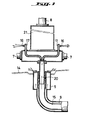
- the water supply tube 15 for feeding water to the water dischargers is, as shown in Figs. 1 and 3, inserted into the water supply pipe 9 for supplying water into the vessel, thereby making the apparatus as a whole compact.
- a path 20 is formed in the steady rest bearing. Water is supplied through the path into the water dischargers which are arranged around the rotary shaft and, therefore, the water supply tube is not exposed to the interior of the vessel and the interior space of the vessel.
- a float chamber 21 is disposed, as illustrated in Figs. 1 and 3, on the rotary shaft at a position above the rotary rods and serves to make the rotary shaft buoyant to reduce the load exerted on the bearings, thereby protecting the bearings from damage or injury and decreasing the energy required for the driving of the rotary shaft. Furthermore, since the mass of swollen pulp is pushed up by water and floats within the vessel, the float chamber which protrudes from the surface of the rotary shaft gives additional support to the floating mass of pulp against sinking down. Since the float chamber is buoyant even when it additionally supports the mass of pulp which is pushed up by water, there is little influence by that load.
- the float chamber has the interior thereof hollowed and preferably vacuumized or sealed with a gas such as air etc. as shown in Fig. 3.
- the float chamber may be disposed concentrically around the rotary shaft.
- a plurality of hollow pipes may be disposed around the rotary shaft.
- Water distribution pipes 23 each having a water outlet 22 which opens to the interior of the vessel are attached to the side wall of the vessel at positions above the rotary rods and above the position at which the pulp is diluted.
- the water fed from the water distribution pipes 23 is absorbed by the pulp to effectively swell the pulp, and helps to dilute the pulp.
- the amount of water spurted from the water distribution pipes may be controlled in advance by the timer 18, similarly to the case of the water dischargers 17, in accordance with the amount of pulp to be thrown into the vessel, the amount of slurry to be taken out of the vessel, the slurry concentration, etc.
- the pulp introduced from the pulp inlet 3 into the vessel, as illustrated in Fig. 1, floats in the water and absorbs the water to be swollen.
- the water distributed from the water distribution pipes 23 aids in swelling the pulp.
- the mass of pulp descends.
- the mass of pulp is pushed up by the water supplied from the lower portion of the vessel and supported by the float chamber 21 in the floating state.
- the dilution of the pulp begins at the surface of contact between the pulp and the water.
- the slurry into which the mass of pulp is diluted is scraped and collected by the scraper plates 6 of the rotary rods 7 and discharged out of the vessel through the slurry outlet.
- the slurry concentration is low, water is spurted from the water dischargers 17 to facilitate the dilution of the pulp, whereas when the slurry concentration is high, the increased torque of the driving machine 10 is detected and the amount of the water supplied from the water supply pipe 9 is increased in proportion to the increase in torque.
- the amount of the water both from the water dischargers and from the water supply pipe is adjusted by detecting the torque of the rotary shaft and effecting the opening and shutting of the valves 11 and 19. In the stationary state, these valves may be operated by the timer 18.
- the volume of the vessel was 423.9 m 3 and the yield of pulp per day was 100 tons.
- the power required for the driving machine 10, the stirrer 24 and a pump for the diluting water was respectively 2.2 KW, 2.2 KW and 11 KW.
- the total power was therefore 15.4 KW.
- the power required was 44 KW in total because two stirrers having power of 15 KW were required although a diluting water pump having power of 11 KW was used. According to the present invention, therefore, 65% of power could be saved in comparison with the conventional apparatus.
- the present apparatus is much superior because it can store therein 25% of the solid content of the pulp. This means that the present apparatus can be utilized more effectively by 30% when calculated in terms of the volume of the vessel than the conventional apparatus.
- the apparatus of the present invention is superior in consumption of heat energy. To be specific, when one tone of pulp having the solid content of 18% in the conventional apparatus was heated so that the increase in temperature might become 10°C, 48,555 Kcal of heat energy was required. On the other hand, when one ton pulp having the solid content of 25% in the present apparatus was treated, the required heat energy was 33,000 Kcal. 15,555 Kcal of heat energy which corresponds to 1.414 I per ton of the pulp when calculated in terms of fuel oil C could therefore be saved according to the present invention.
- the present invention substantially solves adverse problems which have heretofore remained unsolved in the conventionally known apparatuses and, therefore, the invention provides a substantial contribution to the field.
Landscapes
- Engineering & Computer Science (AREA)
- Mechanical Engineering (AREA)
- Paper (AREA)
Applications Claiming Priority (2)
| Application Number | Priority Date | Filing Date | Title |
|---|---|---|---|
| JP75494/82 | 1982-05-07 | ||
| JP57075494A JPS58197392A (ja) | 1982-05-07 | 1982-05-07 | パルプ溶解装置 |
Publications (3)
| Publication Number | Publication Date |
|---|---|
| EP0094061A2 EP0094061A2 (en) | 1983-11-16 |
| EP0094061A3 EP0094061A3 (en) | 1984-10-17 |
| EP0094061B1 true EP0094061B1 (en) | 1987-11-19 |
Family
ID=13577878
Family Applications (1)
| Application Number | Title | Priority Date | Filing Date |
|---|---|---|---|
| EP83104497A Expired EP0094061B1 (en) | 1982-05-07 | 1983-05-06 | Apparatus for dissolution of pulp |
Country Status (4)
| Country | Link |
|---|---|
| US (1) | US4521380A (da) |
| EP (1) | EP0094061B1 (da) |
| JP (1) | JPS58197392A (da) |
| DE (1) | DE3374572D1 (da) |
Families Citing this family (7)
| Publication number | Priority date | Publication date | Assignee | Title |
|---|---|---|---|---|
| FR2593031B1 (fr) * | 1986-01-22 | 1991-07-26 | Latreyte Suzanne | Machine agricole ecaleuse de noix. |
| US4827563A (en) * | 1986-09-16 | 1989-05-09 | Gordon Len C | Tank cleaning apparatus and method |
| JPH0791796B2 (ja) * | 1987-06-05 | 1995-10-04 | 徳七 山崎 | 製紙用紙料の堆積装置 |
| AT394738B (de) * | 1990-09-03 | 1992-06-10 | Andritz Ag Maschf | Verfahren und vorrichtung zum austragen eines mediums aus einem behaelter |
| FI3382U1 (fi) * | 1997-11-14 | 1998-04-29 | Kvaerner Pulping Tech | Varastointitorni massaa varten |
| JP5724078B2 (ja) * | 2010-12-16 | 2015-05-27 | デュプロ精工株式会社 | 古紙再生処理装置 |
| CN112411241B (zh) * | 2020-10-26 | 2021-10-26 | 华南理工大学 | 一种纤维分级方法和分级式布浆装置 |
Family Cites Families (19)
| Publication number | Priority date | Publication date | Assignee | Title |
|---|---|---|---|---|
| US323456A (en) * | 1885-08-04 | Steaming and ore-scouring apparatus | ||
| CA699304A (en) * | 1964-12-08 | E. Palmer Charles | Filter bed agitator | |
| US1307329A (en) * | 1919-06-17 | Apparatus eor treating solid-bearing solutions | ||
| GB190520865A (en) * | 1905-10-14 | 1906-05-10 | Lamartine Cavaignac Trent | Improvements in or relating to Agitating and Mixing Apparatus |
| US1181973A (en) * | 1911-07-07 | 1916-05-02 | Frank Tyson | Mixing apparatus. |
| US1268592A (en) * | 1916-07-29 | 1918-06-04 | Minnetonna Company | Agitator and ripener. |
| US2348123A (en) * | 1940-09-13 | 1944-05-02 | Infilco Inc | Treatment of liquid |
| US2322720A (en) * | 1942-03-27 | 1943-06-22 | Dorr Co | Apparatus for the treatment of liquid solids mixtures |
| US2627978A (en) * | 1948-12-27 | 1953-02-10 | Curtis Paul Aivie | Floating thickener |
| US2663553A (en) * | 1952-07-02 | 1953-12-22 | Wallace & Tiernan Co Inc | Dissolving apparatus |
| US3438743A (en) * | 1963-11-04 | 1969-04-15 | Mo Och Domsjoe Ab | Apparatus for sulphonating and/or sulphating organic compounds controlling the rate of feed of the reactant by measurement of the viscosity of the reaction mixture |
| GB1201635A (en) * | 1966-10-20 | 1970-08-12 | Defibrator Ab | Improvements in or relating to dewaterers for a fibre pulp suspension |
| US3992248A (en) * | 1969-05-19 | 1976-11-16 | Stadler Hurter Limited | Continuous feeding system for treatment towers |
| JPS5148160B2 (da) * | 1972-05-10 | 1976-12-18 | ||
| US4105494A (en) * | 1973-01-05 | 1978-08-08 | Sunds Aktiebolag | Process of gas-phase bleaching high consistency finely disintegrated pulp |
| US4190490A (en) * | 1974-04-03 | 1980-02-26 | Domtar Inc. | Impregnation and digestion of wood chips |
| JPS5537638A (en) * | 1978-09-07 | 1980-03-15 | Nippon Telegr & Teleph Corp <Ntt> | Information processor |
| JPS5576186A (en) * | 1978-12-01 | 1980-06-09 | Masashi Kobayashi | Aging apparatus of beaten paper stock for paper making |
| US4305907A (en) * | 1978-12-18 | 1981-12-15 | Artisan Industries, Inc. | Liquid-liquid extraction apparatus |
-
1982
- 1982-05-07 JP JP57075494A patent/JPS58197392A/ja active Granted
-
1983
- 1983-04-26 US US06/489,411 patent/US4521380A/en not_active Expired - Lifetime
- 1983-05-06 EP EP83104497A patent/EP0094061B1/en not_active Expired
- 1983-05-06 DE DE8383104497T patent/DE3374572D1/de not_active Expired
Also Published As
| Publication number | Publication date |
|---|---|
| JPS58197392A (ja) | 1983-11-17 |
| EP0094061A2 (en) | 1983-11-16 |
| EP0094061A3 (en) | 1984-10-17 |
| JPH0220759B2 (da) | 1990-05-10 |
| US4521380A (en) | 1985-06-04 |
| DE3374572D1 (en) | 1987-12-23 |
Similar Documents
| Publication | Publication Date | Title |
|---|---|---|
| US8309031B2 (en) | Gas hydrate production apparatus | |
| EP0094061B1 (en) | Apparatus for dissolution of pulp | |
| US20210389051A1 (en) | High-performance, energy-saving, automatic cooper-melting apparatus | |
| US4304176A (en) | Apparatus for the wet crushing of material | |
| US6579438B1 (en) | Molten salt electrolytic cell having metal reservoir | |
| US4544004A (en) | Filler unit for topping up a container with liquid | |
| US4902410A (en) | Interceptor for the continuous removal of solid matter from a mixture of solids and liquid | |
| CN209519757U (zh) | 一种恒温磁力搅拌器 | |
| JP2006289320A (ja) | 液体濃縮装置 | |
| US4904420A (en) | Method and a device for introducing a gas into a liquid | |
| JP4488788B2 (ja) | 気相式と満液式の連続蒸解缶に用いるトップセパレーターおよび蒸解缶運転モードの転換方法 | |
| SU1351655A1 (ru) | Моечна машина дл зерна | |
| SU1253994A1 (ru) | Горизонтальный противоточный экстрактор дл получени эфирного масла | |
| JPH0260791B2 (da) | ||
| JPH0467972B2 (da) | ||
| SU1214324A1 (ru) | Установка дл гранул ции металлического расплава | |
| SU1127619A1 (ru) | Колонный аппарат | |
| JPH10174862A (ja) | 連続反応装置 | |
| GB1591731A (en) | Degassing apparatus | |
| FI69870C (fi) | Foerfarande foer anordning foer behandling av ett grusliknandematerial med ett fluidium | |
| EP0053156A1 (en) | Introducing grain into, and removing grain from, storage apparatus | |
| JPS57113891A (en) | Aerating device | |
| SU1321706A1 (ru) | Устройство дл переработки металлургического шлака | |
| JPS5833169B2 (ja) | 活性炭の脱水供給装置 | |
| CA1302397C (en) | Method and apparatus for forming small bubbles in liquid |
Legal Events
| Date | Code | Title | Description |
|---|---|---|---|
| PUAI | Public reference made under article 153(3) epc to a published international application that has entered the european phase |
Free format text: ORIGINAL CODE: 0009012 |
|
| AK | Designated contracting states |
Designated state(s): DE FR SE |
|
| PUAL | Search report despatched |
Free format text: ORIGINAL CODE: 0009013 |
|
| AK | Designated contracting states |
Designated state(s): DE FR SE |
|
| 17P | Request for examination filed |
Effective date: 19850411 |
|
| 17Q | First examination report despatched |
Effective date: 19860303 |
|
| GRAA | (expected) grant |
Free format text: ORIGINAL CODE: 0009210 |
|
| AK | Designated contracting states |
Kind code of ref document: B1 Designated state(s): DE FR SE |
|
| REF | Corresponds to: |
Ref document number: 3374572 Country of ref document: DE Date of ref document: 19871223 |
|
| ET | Fr: translation filed | ||
| PLBE | No opposition filed within time limit |
Free format text: ORIGINAL CODE: 0009261 |
|
| STAA | Information on the status of an ep patent application or granted ep patent |
Free format text: STATUS: NO OPPOSITION FILED WITHIN TIME LIMIT |
|
| 26N | No opposition filed | ||
| EAL | Se: european patent in force in sweden |
Ref document number: 83104497.9 |
|
| PGFP | Annual fee paid to national office [announced via postgrant information from national office to epo] |
Ref country code: FR Payment date: 19990525 Year of fee payment: 17 |
|
| PGFP | Annual fee paid to national office [announced via postgrant information from national office to epo] |
Ref country code: SE Payment date: 19990531 Year of fee payment: 17 |
|
| PGFP | Annual fee paid to national office [announced via postgrant information from national office to epo] |
Ref country code: DE Payment date: 19990728 Year of fee payment: 17 |
|
| PG25 | Lapsed in a contracting state [announced via postgrant information from national office to epo] |
Ref country code: SE Free format text: LAPSE BECAUSE OF NON-PAYMENT OF DUE FEES Effective date: 20000507 |
|
| EUG | Se: european patent has lapsed |
Ref document number: 83104497.9 |
|
| PG25 | Lapsed in a contracting state [announced via postgrant information from national office to epo] |
Ref country code: FR Free format text: LAPSE BECAUSE OF NON-PAYMENT OF DUE FEES Effective date: 20010131 |
|
| PG25 | Lapsed in a contracting state [announced via postgrant information from national office to epo] |
Ref country code: DE Free format text: LAPSE BECAUSE OF NON-PAYMENT OF DUE FEES Effective date: 20010301 |
|
| REG | Reference to a national code |
Ref country code: FR Ref legal event code: ST |