EP0094122A1 - Klemme - Google Patents
Klemme Download PDFInfo
- Publication number
- EP0094122A1 EP0094122A1 EP83200626A EP83200626A EP0094122A1 EP 0094122 A1 EP0094122 A1 EP 0094122A1 EP 83200626 A EP83200626 A EP 83200626A EP 83200626 A EP83200626 A EP 83200626A EP 0094122 A1 EP0094122 A1 EP 0094122A1
- Authority
- EP
- European Patent Office
- Prior art keywords
- receiving member
- bracket
- screwthreaded
- screwthread
- clamp
- Prior art date
- Legal status (The legal status is an assumption and is not a legal conclusion. Google has not performed a legal analysis and makes no representation as to the accuracy of the status listed.)
- Granted
Links
- 239000000463 material Substances 0.000 claims abstract description 6
- 238000005452 bending Methods 0.000 claims abstract description 5
- RYGMFSIKBFXOCR-UHFFFAOYSA-N Copper Chemical compound [Cu] RYGMFSIKBFXOCR-UHFFFAOYSA-N 0.000 claims description 4
- 239000010949 copper Substances 0.000 claims description 4
- 229910052802 copper Inorganic materials 0.000 claims description 4
- 238000005260 corrosion Methods 0.000 description 5
- 230000007797 corrosion Effects 0.000 description 5
- 238000009718 spray deposition Methods 0.000 description 4
- 229910000881 Cu alloy Inorganic materials 0.000 description 2
- HCHKCACWOHOZIP-UHFFFAOYSA-N Zinc Chemical compound [Zn] HCHKCACWOHOZIP-UHFFFAOYSA-N 0.000 description 2
- 230000000694 effects Effects 0.000 description 2
- 238000000034 method Methods 0.000 description 2
- 239000011701 zinc Substances 0.000 description 2
- 229910052725 zinc Inorganic materials 0.000 description 2
- 229910001369 Brass Inorganic materials 0.000 description 1
- 230000001154 acute effect Effects 0.000 description 1
- 239000010951 brass Substances 0.000 description 1
- 238000005266 casting Methods 0.000 description 1
- 238000007796 conventional method Methods 0.000 description 1
- 231100001261 hazardous Toxicity 0.000 description 1
- 238000004519 manufacturing process Methods 0.000 description 1
Images

Classifications
-
- H—ELECTRICITY
- H01—ELECTRIC ELEMENTS
- H01R—ELECTRICALLY-CONDUCTIVE CONNECTIONS; STRUCTURAL ASSOCIATIONS OF A PLURALITY OF MUTUALLY-INSULATED ELECTRICAL CONNECTING ELEMENTS; COUPLING DEVICES; CURRENT COLLECTORS
- H01R4/00—Electrically-conductive connections between two or more conductive members in direct contact, i.e. touching one another; Means for effecting or maintaining such contact; Electrically-conductive connections having two or more spaced connecting locations for conductors and using contact members penetrating insulation
- H01R4/28—Clamped connections, spring connections
- H01R4/30—Clamped connections, spring connections utilising a screw or nut clamping member
- H01R4/36—Conductive members located under tip of screw
-
- F—MECHANICAL ENGINEERING; LIGHTING; HEATING; WEAPONS; BLASTING
- F16—ENGINEERING ELEMENTS AND UNITS; GENERAL MEASURES FOR PRODUCING AND MAINTAINING EFFECTIVE FUNCTIONING OF MACHINES OR INSTALLATIONS; THERMAL INSULATION IN GENERAL
- F16L—PIPES; JOINTS OR FITTINGS FOR PIPES; SUPPORTS FOR PIPES, CABLES OR PROTECTIVE TUBING; MEANS FOR THERMAL INSULATION IN GENERAL
- F16L3/00—Supports for pipes, cables or protective tubing, e.g. hangers, holders, clamps, cleats, clips, brackets
- F16L3/08—Supports for pipes, cables or protective tubing, e.g. hangers, holders, clamps, cleats, clips, brackets substantially surrounding the pipe, cable or protective tubing
- F16L3/12—Supports for pipes, cables or protective tubing, e.g. hangers, holders, clamps, cleats, clips, brackets substantially surrounding the pipe, cable or protective tubing comprising a member substantially surrounding the pipe, cable or protective tubing
- F16L3/133—Supports for pipes, cables or protective tubing, e.g. hangers, holders, clamps, cleats, clips, brackets substantially surrounding the pipe, cable or protective tubing comprising a member substantially surrounding the pipe, cable or protective tubing and hanging from a pendant
-
- H—ELECTRICITY
- H01—ELECTRIC ELEMENTS
- H01R—ELECTRICALLY-CONDUCTIVE CONNECTIONS; STRUCTURAL ASSOCIATIONS OF A PLURALITY OF MUTUALLY-INSULATED ELECTRICAL CONNECTING ELEMENTS; COUPLING DEVICES; CURRENT COLLECTORS
- H01R4/00—Electrically-conductive connections between two or more conductive members in direct contact, i.e. touching one another; Means for effecting or maintaining such contact; Electrically-conductive connections having two or more spaced connecting locations for conductors and using contact members penetrating insulation
- H01R4/58—Electrically-conductive connections between two or more conductive members in direct contact, i.e. touching one another; Means for effecting or maintaining such contact; Electrically-conductive connections having two or more spaced connecting locations for conductors and using contact members penetrating insulation characterised by the form or material of the contacting members
- H01R4/64—Connections between or with conductive parts having primarily a non-electric function, e.g. frame, casing, rail
Definitions
- the invention relates to a bracket for holding at least one object comprising a body having an internally screwthreaded bore, a screwthreaded element such as a bolt engaging said bore and a member receiving the object and extending away from said body.
- a bracket of this kind is, for example, a clamp for fastening a connecting lead to a ground electrode.
- the body and the receiving member are made by spray-casting brass, by casting or thermopressing a similar copper alloy or from an extruded profile.
- the receiving member surrounds an opening in which the ground electrode and the connecting lead are arranged in common and firmly clamped together by the screwthreaded element in the form of a bolt extending in the opening of the receiving member.
- the object of the invention is to provide such a clamp and, in general, a bracket of the kind set forth in the preamble which can be manufactured at lower costs.
- a bracket according to the invention this is achieved by using a receiving member of bent sheet material and by forming the body from at least one semi-cylindrical end of the receiving member provided with internal screwthread and an annular element, for example, a ring or sleeve surrounding said end and engaging the screwthreaded element.
- an annular element for example, a ring or sleeve surrounding said end and engaging the screwthreaded element.
- the bracket embodying the invention can be used, be it with other dimensions.
- the bracket can be mounted in a very simple manner by putting the receiving member around the tube, by bending it and by bringing the end or the ends of the receiving member into contact with the screwthreaded element. By subsequently slipping the annular element onto the end, this end is fixed in place with respect to the screwthreaded element so that a firm connection is established.
- bracket embodying the invention intended to support light-weight tubes or ducts it is sufficient to bring one end of the receiving member into contact with the screwthread of the screwthreaded element.
- the bracket embodying the invention can not only support an object but also clamp it tight, for example, like a clamp for fastening a connecting wire to a ground electrode as described above.
- the screwthreaded element has a length such that it can come into contact with the object across the opening in the body, whilst the receiving member is outwardly bent with respect to a tangential line to the adjacent end.
- the bracket is tightened by forcibly screwing the screwthreaded element against the object, the outwardly bent parts of the receiving member adjacent the ends are exposed to an inwardly directed reactive force.
- the ends having internal screwthread are more strongly pressed against the screwthreaded element so that a satisfactory transfer of effort and, in addition, a guard effect are obtained.
- a rim of the end protruding beyond the annular element is bent over outwardly.
- the annular element can thus be slipped onto the ends when the latter are pinched towards one another without the screwthreaded element being present. When the screwthreaded element is put in place, this inward movement is no longer possible so that the annular element is locked up.
- a disadvantage not yet mentioned of the known clamp made by spray casting for fastening a ground electrode to a connecting wire resides in that this clamp is very sensitive to corrosion so that a satisfactory electric contact between the ground electrode and the connecting wire becomes hazardous.
- a further object of the invention is, therefore, to provide a clamp which is resistant to corrosion.
- a bracket embodying the invention intended to fasten a connecting wire to a ground electrode this is achieved by making the receiving member from copper.
- the copper alloy used for spray casting the known clamp must necessarily contain much zinc. This high percentage of zinc involves unfavourable corrosion properties for the clamp. Since the clamp embodying the invention is made from sheet material, copper can be used, the corrosion behaviour of which is very advantageous.
- the screwthreaded element used for such a clamp is preferably a cuprodur bolt having appropriate strength together with satisfactory resistance to corrosion.
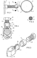
- the bracket embodying the invention serves to support a tube 8 with respect to a wall 7. From the wall 7 protrudes a screwthreaded element 6 formed by a screwthreaded rod.
- the tube is lying in a curved part of a receiving member 4.
- the receiving member 4 has an end 3 bent in a semi-cylindrical shape.
- the semi-cylindrical inner surface of the end 3 has internal screwthread.
- the internal screwthread of the end 3 engages the external screwthread of the screwthreaded rod 6.
- a ring 5 is arranged around the end 3 of the receiving member 4 and the screwthreaded element 6.
- the ring 5 locks the end 3 both in an axial and a radial direction of the screwthreaded element 6.
- the semi-cylindrical end 3 of the receiving member 4 constitutes, together with the ring 5, the body 2 of the bracket 1.
- the bracket 1 For mounting the bracket 1, first the ring 5 is slipped onto the screwthreaded rod 6. Subsequently the end 3 is put on the screwthreaded rod 6 at the appropriate distance from the wall 7. Simply by shifting the ring 5 back along the end 3, the bracket 1 is mounted.
- the receiving member 12 of the bracket 10 is bent round in an uninterrupted shape and the body 11 comprises the two ends 13 of the receiving member 12.
- the body 11 comprises furthermore a ring 14 extending around the ends 13.
- the bracket 10 is particularly intended to clamp a connecting wire 16 to a ground electrode 15.
- the two ends 13 of the receiving member 12 are bent into a semi-cylindrical shape and the inner surface of said ends has a screwthread 18.
- a bolt 17 can engage the screwthread 18.
- the ends 13 are held together by the ring 14 so that the bolt 17 can strongly clamp the ground electrode 15 located in the receiving member 12 against the connecting wire 16 without deflection of the ends 13 of the receiving member.
- the receiving member 12 is made from a strip of sheet material.
- the outermost rim of the receiving member 12 is bent over outwardly.
- the ring 11 can be arranged across the rim 19 and around the ends 13 of the receiving member 12 by pinching said ends towards one another.
- the bolt 17 is mounted, the ring 14 is thus locked in place by the rim 19.
- the parts 20 of the receiving member 12 are outwardly bent with respect to a tangential line 21 starting from the adjacent end 13 to the ground electrode 15.
- the parts 20 are exposed to a reactive force tending to stretch said parts 20.
- Fig. 4 it will be apparent that in this way the lower parts of the ends 13, that is to say the parts neighbouring the parts 20 are compelled towards one another. This results in that the engagement between the screwthread 18 and the bolt 17 is strengthened and, moreover, the bolt 17 is guarded by the clamping effect.
- the receiving member 20 is furthermore advantageously provided at its lower end with an acute corner 22 so that the connecting wire 16 is guarded against a turn.
- the receiving member 12 may be made from any suitable sheet material and for the use shown in Figs. 3 and 4 it is made from copper sheet.
- the bracket shown in Fig. 5 serves for suspending a tube 26.
- the ends 27 of the receiving member are also bent semi-cylindrically and provided with internal screwthread.
- the screwthread of said ends 27 engages the screwthread 30 of a rod 29.
- the ends 27 are fixed in a cylindrical form by the ring 28.
- the ring 28 is guarded by a nut 31.
- the bracket embodying the invention is a particularly simple operation. After the supporting rods 29 are arranged at suitable intervals, the tube 26 can be simply suspended by bending the receiving member around the tube, by bringing the ends 27 into contact with the screwthread 30 and by subsequently slipping the ring 28 slipped earlier onto the rod 29 onto the ends 27.
- the ends 37 are comparatively long. This has the advantage that the bracket 35 can be arranged over a relatively large distance in a vertical direction at different heights.
- the ends 37 are simply laid at the desired height against the screwthread 38 of the supporting rod 39, after which the sleeve 40 is slipped around the ends 37.
- the region in which the level of the top side of the ends 37 may varie is indicated in Fig. 6 by the arrow 42.
- the receiving member of the bracket 35 has two halves 36. Each half 36 has a bend part 41 and a screwthreaded, semi-cylindrical end 37.
- the bracket 35 may, of course, also be a closed member.
Landscapes
- Engineering & Computer Science (AREA)
- General Engineering & Computer Science (AREA)
- Mechanical Engineering (AREA)
- Clamps And Clips (AREA)
- Supports For Pipes And Cables (AREA)
- Wire Bonding (AREA)
- Gripping Jigs, Holding Jigs, And Positioning Jigs (AREA)
- Prevention Of Electric Corrosion (AREA)
Priority Applications (1)
| Application Number | Priority Date | Filing Date | Title |
|---|---|---|---|
| AT83200626T ATE21159T1 (de) | 1982-05-06 | 1983-05-02 | Klemme. |
Applications Claiming Priority (2)
| Application Number | Priority Date | Filing Date | Title |
|---|---|---|---|
| NL8201862A NL8201862A (nl) | 1982-05-06 | 1982-05-06 | Beugel. |
| NL8201862 | 1982-05-06 |
Publications (2)
| Publication Number | Publication Date |
|---|---|
| EP0094122A1 true EP0094122A1 (de) | 1983-11-16 |
| EP0094122B1 EP0094122B1 (de) | 1986-07-30 |
Family
ID=19839696
Family Applications (1)
| Application Number | Title | Priority Date | Filing Date |
|---|---|---|---|
| EP83200626A Expired EP0094122B1 (de) | 1982-05-06 | 1983-05-02 | Klemme |
Country Status (5)
| Country | Link |
|---|---|
| EP (1) | EP0094122B1 (de) |
| AT (1) | ATE21159T1 (de) |
| CA (1) | CA1205539A (de) |
| DE (1) | DE3364896D1 (de) |
| NL (1) | NL8201862A (de) |
Cited By (7)
| Publication number | Priority date | Publication date | Assignee | Title |
|---|---|---|---|---|
| DE9103295U1 (de) * | 1991-03-18 | 1991-06-20 | J. Van Walraven B.V., Mijdrecht | Aufhängevorrichtung, insbesondere für eine Rohrschelle |
| FR2702015A1 (fr) * | 1993-02-24 | 1994-09-02 | Ledant Thierry | Serre-tube. |
| GB2336622A (en) * | 1998-04-24 | 1999-10-27 | Bloxwich Transport Prod Ltd | Cable security seal |
| GB2445022A (en) * | 2006-12-20 | 2008-06-25 | W J Furse And Co Ltd | Clamp for holding a cable to a supporting line. |
| CN104253322A (zh) * | 2013-06-26 | 2014-12-31 | 江苏新丰电子有限公司 | 一种新型的八分之五接线铜环 |
| CN113451797A (zh) * | 2021-08-02 | 2021-09-28 | 芜湖市凯鑫避雷器有限责任公司 | 一种具有防松动结构的避雷器接地装置 |
| CN115681634A (zh) * | 2021-07-28 | 2023-02-03 | 帕尔公司 | 管件保持器 |
Families Citing this family (1)
| Publication number | Priority date | Publication date | Assignee | Title |
|---|---|---|---|---|
| WO2004101915A1 (en) * | 2003-05-15 | 2004-11-25 | Wayne Peter Killip | Shaft clamp assembly |
Citations (3)
| Publication number | Priority date | Publication date | Assignee | Title |
|---|---|---|---|---|
| US3493206A (en) * | 1968-04-25 | 1970-02-03 | Cabot Corp | Adjustable pipe hanger |
| FR2406147A1 (fr) * | 1977-10-17 | 1979-05-11 | Hilti Ag | Fixation a ecartement |
| GB2097508A (en) * | 1981-04-27 | 1982-11-03 | Michigan Hanger | Apparatus for supporting a tubular member |
-
1982
- 1982-05-06 NL NL8201862A patent/NL8201862A/nl not_active Application Discontinuation
-
1983
- 1983-05-02 DE DE8383200626T patent/DE3364896D1/de not_active Expired
- 1983-05-02 AT AT83200626T patent/ATE21159T1/de not_active IP Right Cessation
- 1983-05-02 EP EP83200626A patent/EP0094122B1/de not_active Expired
- 1983-05-06 CA CA000427654A patent/CA1205539A/en not_active Expired
Patent Citations (3)
| Publication number | Priority date | Publication date | Assignee | Title |
|---|---|---|---|---|
| US3493206A (en) * | 1968-04-25 | 1970-02-03 | Cabot Corp | Adjustable pipe hanger |
| FR2406147A1 (fr) * | 1977-10-17 | 1979-05-11 | Hilti Ag | Fixation a ecartement |
| GB2097508A (en) * | 1981-04-27 | 1982-11-03 | Michigan Hanger | Apparatus for supporting a tubular member |
Cited By (8)
| Publication number | Priority date | Publication date | Assignee | Title |
|---|---|---|---|---|
| DE9103295U1 (de) * | 1991-03-18 | 1991-06-20 | J. Van Walraven B.V., Mijdrecht | Aufhängevorrichtung, insbesondere für eine Rohrschelle |
| FR2702015A1 (fr) * | 1993-02-24 | 1994-09-02 | Ledant Thierry | Serre-tube. |
| GB2336622A (en) * | 1998-04-24 | 1999-10-27 | Bloxwich Transport Prod Ltd | Cable security seal |
| GB2445022A (en) * | 2006-12-20 | 2008-06-25 | W J Furse And Co Ltd | Clamp for holding a cable to a supporting line. |
| CN104253322A (zh) * | 2013-06-26 | 2014-12-31 | 江苏新丰电子有限公司 | 一种新型的八分之五接线铜环 |
| CN115681634A (zh) * | 2021-07-28 | 2023-02-03 | 帕尔公司 | 管件保持器 |
| CN113451797A (zh) * | 2021-08-02 | 2021-09-28 | 芜湖市凯鑫避雷器有限责任公司 | 一种具有防松动结构的避雷器接地装置 |
| CN113451797B (zh) * | 2021-08-02 | 2024-03-15 | 芜湖市凯鑫避雷器有限责任公司 | 一种具有防松动结构的避雷器接地装置 |
Also Published As
| Publication number | Publication date |
|---|---|
| NL8201862A (nl) | 1983-12-01 |
| ATE21159T1 (de) | 1986-08-15 |
| CA1205539A (en) | 1986-06-03 |
| DE3364896D1 (en) | 1986-09-04 |
| EP0094122B1 (de) | 1986-07-30 |
Similar Documents
| Publication | Publication Date | Title |
|---|---|---|
| EP0118986B1 (de) | Eine selbsttragende Basis für eine Klammer zum Befestigen eines Kabels oder Ähnlichem an einem Trägerkanal | |
| US5947424A (en) | Pipe support assembly with retaining strap | |
| EP0400687B1 (de) | Gewelltes Wärmerohr | |
| US4176815A (en) | Variable spring hanger assembly | |
| US2956108A (en) | Connector | |
| US4533205A (en) | Collapsible wedge for electrical connector | |
| US4347433A (en) | Heat transfer apparatus for releasably securing heating or cooling means to pipe | |
| US4526437A (en) | Electrical bracket | |
| AU695714B2 (en) | Pipe and cable clamp with base part and receiving strap | |
| US3684221A (en) | Helical suspension clamp assembly | |
| US2068368A (en) | Securing device | |
| US3987877A (en) | Trolley busway housing | |
| US4290572A (en) | Pipe clamp device | |
| US3173639A (en) | Cable holder and method of manufacture and installation thereof | |
| US4934634A (en) | Pipe hanger | |
| EP0094122B1 (de) | Klemme | |
| EP0713039B1 (de) | Rohrschelle und Verfahren zu deren Herstellung | |
| US4099319A (en) | Method of assembly of electric heating element with bulkhead fitting | |
| US4940857A (en) | Insulator for overhead electric wires | |
| US5564659A (en) | Conduit hanging apparatus | |
| US4641989A (en) | Pipe hanger extension clip | |
| US20070180662A1 (en) | Compression or expansion mountable support band | |
| US3358953A (en) | Conductor clamp | |
| US5132517A (en) | Electric glow element | |
| US6441303B1 (en) | Device for electrically contacting and sealing a tubular member |
Legal Events
| Date | Code | Title | Description |
|---|---|---|---|
| PUAI | Public reference made under article 153(3) epc to a published international application that has entered the european phase |
Free format text: ORIGINAL CODE: 0009012 |
|
| AK | Designated contracting states |
Designated state(s): AT BE CH DE FR GB IT LI LU NL SE |
|
| 17P | Request for examination filed |
Effective date: 19840515 |
|
| GRAA | (expected) grant |
Free format text: ORIGINAL CODE: 0009210 |
|
| ITF | It: translation for a ep patent filed | ||
| AK | Designated contracting states |
Kind code of ref document: B1 Designated state(s): AT BE CH DE FR GB IT LI LU NL SE |
|
| REF | Corresponds to: |
Ref document number: 21159 Country of ref document: AT Date of ref document: 19860815 Kind code of ref document: T |
|
| REF | Corresponds to: |
Ref document number: 3364896 Country of ref document: DE Date of ref document: 19860904 |
|
| ET | Fr: translation filed | ||
| PLBI | Opposition filed |
Free format text: ORIGINAL CODE: 0009260 |
|
| PG25 | Lapsed in a contracting state [announced via postgrant information from national office to epo] |
Ref country code: LU Free format text: LAPSE BECAUSE OF NON-PAYMENT OF DUE FEES Effective date: 19870531 |
|
| PGFP | Annual fee paid to national office [announced via postgrant information from national office to epo] |
Ref country code: NL Payment date: 19870531 Year of fee payment: 5 |
|
| 26 | Opposition filed |
Opponent name: SIEMENS AKTIENGESELLSCHAFT, BERLIN UND MUENCHEN Effective date: 19870427 |
|
| NLR1 | Nl: opposition has been filed with the epo |
Opponent name: SIEMENS AKTIENGESELLSCHAFT |
|
| RDAG | Patent revoked |
Free format text: ORIGINAL CODE: 0009271 |
|
| STAA | Information on the status of an ep patent application or granted ep patent |
Free format text: STATUS: PATENT REVOKED |
|
| GBPR | Gb: patent revoked under art. 102 of the ep convention designating the uk as contracting state | ||
| 27W | Patent revoked |
Effective date: 19880508 |
|
| REG | Reference to a national code |
Ref country code: CH Ref legal event code: PL |
|
| NLR2 | Nl: decision of opposition | ||
| BERE | Be: lapsed |
Owner name: ERICO EUROPA B.V. Effective date: 19880531 |
|
| EUG | Se: european patent has lapsed |
Ref document number: 83200626.6 |