EP0094158B1 - Système de lentille intraoculaire bifocale - Google Patents
Système de lentille intraoculaire bifocale Download PDFInfo
- Publication number
- EP0094158B1 EP0094158B1 EP83302121A EP83302121A EP0094158B1 EP 0094158 B1 EP0094158 B1 EP 0094158B1 EP 83302121 A EP83302121 A EP 83302121A EP 83302121 A EP83302121 A EP 83302121A EP 0094158 B1 EP0094158 B1 EP 0094158B1
- Authority
- EP
- European Patent Office
- Prior art keywords
- lens
- frame
- axis
- eye
- structure according
- Prior art date
- Legal status (The legal status is an assumption and is not a legal conclusion. Google has not performed a legal analysis and makes no representation as to the accuracy of the status listed.)
- Expired
Links
- 210000002159 anterior chamber Anatomy 0.000 claims description 14
- 238000002513 implantation Methods 0.000 claims description 14
- 230000001179 pupillary effect Effects 0.000 claims description 11
- 238000006073 displacement reaction Methods 0.000 claims description 10
- 230000005291 magnetic effect Effects 0.000 claims description 6
- 230000000717 retained effect Effects 0.000 claims description 5
- 239000007943 implant Substances 0.000 claims description 4
- 230000014759 maintenance of location Effects 0.000 claims description 4
- 230000010287 polarization Effects 0.000 claims description 3
- 230000000087 stabilizing effect Effects 0.000 claims description 2
- 239000000725 suspension Substances 0.000 claims 2
- 238000009434 installation Methods 0.000 claims 1
- 230000003287 optical effect Effects 0.000 description 9
- 230000015572 biosynthetic process Effects 0.000 description 4
- 238000005755 formation reaction Methods 0.000 description 4
- 238000000034 method Methods 0.000 description 4
- 230000010339 dilation Effects 0.000 description 2
- 230000000694 effects Effects 0.000 description 2
- 239000000463 material Substances 0.000 description 2
- 210000001747 pupil Anatomy 0.000 description 2
- 125000006850 spacer group Chemical group 0.000 description 2
- 208000002177 Cataract Diseases 0.000 description 1
- VVQNEPGJFQJSBK-UHFFFAOYSA-N Methyl methacrylate Chemical compound COC(=O)C(C)=C VVQNEPGJFQJSBK-UHFFFAOYSA-N 0.000 description 1
- 239000004743 Polypropylene Substances 0.000 description 1
- 210000001124 body fluid Anatomy 0.000 description 1
- 239000010839 body fluid Substances 0.000 description 1
- 210000005069 ears Anatomy 0.000 description 1
- 230000007717 exclusion Effects 0.000 description 1
- 210000004709 eyebrow Anatomy 0.000 description 1
- 230000005298 paramagnetic effect Effects 0.000 description 1
- 239000004033 plastic Substances 0.000 description 1
- -1 polypropylene Polymers 0.000 description 1
- 229920001155 polypropylene Polymers 0.000 description 1
- 230000002441 reversible effect Effects 0.000 description 1
Images


Classifications
-
- A—HUMAN NECESSITIES
- A61—MEDICAL OR VETERINARY SCIENCE; HYGIENE
- A61F—FILTERS IMPLANTABLE INTO BLOOD VESSELS; PROSTHESES; DEVICES PROVIDING PATENCY TO, OR PREVENTING COLLAPSING OF, TUBULAR STRUCTURES OF THE BODY, e.g. STENTS; ORTHOPAEDIC, NURSING OR CONTRACEPTIVE DEVICES; FOMENTATION; TREATMENT OR PROTECTION OF EYES OR EARS; BANDAGES, DRESSINGS OR ABSORBENT PADS; FIRST-AID KITS
- A61F2/00—Filters implantable into blood vessels; Prostheses, i.e. artificial substitutes or replacements for parts of the body; Appliances for connecting them with the body; Devices providing patency to, or preventing collapsing of, tubular structures of the body, e.g. stents
- A61F2/02—Prostheses implantable into the body
- A61F2/14—Eye parts, e.g. lenses or corneal implants; Artificial eyes
- A61F2/16—Intraocular lenses
- A61F2/1613—Intraocular lenses having special lens configurations, e.g. multipart lenses; having particular optical properties, e.g. pseudo-accommodative lenses, lenses having aberration corrections, diffractive lenses, lenses for variably absorbing electromagnetic radiation, lenses having variable focus
-
- A—HUMAN NECESSITIES
- A61—MEDICAL OR VETERINARY SCIENCE; HYGIENE
- A61F—FILTERS IMPLANTABLE INTO BLOOD VESSELS; PROSTHESES; DEVICES PROVIDING PATENCY TO, OR PREVENTING COLLAPSING OF, TUBULAR STRUCTURES OF THE BODY, e.g. STENTS; ORTHOPAEDIC, NURSING OR CONTRACEPTIVE DEVICES; FOMENTATION; TREATMENT OR PROTECTION OF EYES OR EARS; BANDAGES, DRESSINGS OR ABSORBENT PADS; FIRST-AID KITS
- A61F2/00—Filters implantable into blood vessels; Prostheses, i.e. artificial substitutes or replacements for parts of the body; Appliances for connecting them with the body; Devices providing patency to, or preventing collapsing of, tubular structures of the body, e.g. stents
- A61F2/02—Prostheses implantable into the body
- A61F2/14—Eye parts, e.g. lenses or corneal implants; Artificial eyes
- A61F2/16—Intraocular lenses
- A61F2/1613—Intraocular lenses having special lens configurations, e.g. multipart lenses; having particular optical properties, e.g. pseudo-accommodative lenses, lenses having aberration corrections, diffractive lenses, lenses for variably absorbing electromagnetic radiation, lenses having variable focus
- A61F2/1616—Pseudo-accommodative, e.g. multifocal or enabling monovision
- A61F2/1618—Multifocal lenses
-
- A—HUMAN NECESSITIES
- A61—MEDICAL OR VETERINARY SCIENCE; HYGIENE
- A61F—FILTERS IMPLANTABLE INTO BLOOD VESSELS; PROSTHESES; DEVICES PROVIDING PATENCY TO, OR PREVENTING COLLAPSING OF, TUBULAR STRUCTURES OF THE BODY, e.g. STENTS; ORTHOPAEDIC, NURSING OR CONTRACEPTIVE DEVICES; FOMENTATION; TREATMENT OR PROTECTION OF EYES OR EARS; BANDAGES, DRESSINGS OR ABSORBENT PADS; FIRST-AID KITS
- A61F2/00—Filters implantable into blood vessels; Prostheses, i.e. artificial substitutes or replacements for parts of the body; Appliances for connecting them with the body; Devices providing patency to, or preventing collapsing of, tubular structures of the body, e.g. stents
- A61F2/02—Prostheses implantable into the body
- A61F2/14—Eye parts, e.g. lenses or corneal implants; Artificial eyes
- A61F2/16—Intraocular lenses
- A61F2/1613—Intraocular lenses having special lens configurations, e.g. multipart lenses; having particular optical properties, e.g. pseudo-accommodative lenses, lenses having aberration corrections, diffractive lenses, lenses for variably absorbing electromagnetic radiation, lenses having variable focus
- A61F2/1624—Intraocular lenses having special lens configurations, e.g. multipart lenses; having particular optical properties, e.g. pseudo-accommodative lenses, lenses having aberration corrections, diffractive lenses, lenses for variably absorbing electromagnetic radiation, lenses having variable focus having adjustable focus; power activated variable focus means, e.g. mechanically or electrically by the ciliary muscle or from the outside
- A61F2/1632—Intraocular lenses having special lens configurations, e.g. multipart lenses; having particular optical properties, e.g. pseudo-accommodative lenses, lenses having aberration corrections, diffractive lenses, lenses for variably absorbing electromagnetic radiation, lenses having variable focus having adjustable focus; power activated variable focus means, e.g. mechanically or electrically by the ciliary muscle or from the outside for changing radial position, i.e. perpendicularly to the visual axis when implanted
-
- A—HUMAN NECESSITIES
- A61—MEDICAL OR VETERINARY SCIENCE; HYGIENE
- A61F—FILTERS IMPLANTABLE INTO BLOOD VESSELS; PROSTHESES; DEVICES PROVIDING PATENCY TO, OR PREVENTING COLLAPSING OF, TUBULAR STRUCTURES OF THE BODY, e.g. STENTS; ORTHOPAEDIC, NURSING OR CONTRACEPTIVE DEVICES; FOMENTATION; TREATMENT OR PROTECTION OF EYES OR EARS; BANDAGES, DRESSINGS OR ABSORBENT PADS; FIRST-AID KITS
- A61F2/00—Filters implantable into blood vessels; Prostheses, i.e. artificial substitutes or replacements for parts of the body; Appliances for connecting them with the body; Devices providing patency to, or preventing collapsing of, tubular structures of the body, e.g. stents
- A61F2/02—Prostheses implantable into the body
- A61F2/14—Eye parts, e.g. lenses or corneal implants; Artificial eyes
- A61F2/16—Intraocular lenses
- A61F2/1613—Intraocular lenses having special lens configurations, e.g. multipart lenses; having particular optical properties, e.g. pseudo-accommodative lenses, lenses having aberration corrections, diffractive lenses, lenses for variably absorbing electromagnetic radiation, lenses having variable focus
- A61F2/1648—Multipart lenses
-
- A—HUMAN NECESSITIES
- A61—MEDICAL OR VETERINARY SCIENCE; HYGIENE
- A61F—FILTERS IMPLANTABLE INTO BLOOD VESSELS; PROSTHESES; DEVICES PROVIDING PATENCY TO, OR PREVENTING COLLAPSING OF, TUBULAR STRUCTURES OF THE BODY, e.g. STENTS; ORTHOPAEDIC, NURSING OR CONTRACEPTIVE DEVICES; FOMENTATION; TREATMENT OR PROTECTION OF EYES OR EARS; BANDAGES, DRESSINGS OR ABSORBENT PADS; FIRST-AID KITS
- A61F2/00—Filters implantable into blood vessels; Prostheses, i.e. artificial substitutes or replacements for parts of the body; Appliances for connecting them with the body; Devices providing patency to, or preventing collapsing of, tubular structures of the body, e.g. stents
- A61F2/02—Prostheses implantable into the body
- A61F2/14—Eye parts, e.g. lenses or corneal implants; Artificial eyes
- A61F2/16—Intraocular lenses
- A61F2002/1681—Intraocular lenses having supporting structure for lens, e.g. haptics
- A61F2002/1683—Intraocular lenses having supporting structure for lens, e.g. haptics having filiform haptics
Definitions
- the invention relates to intraocular lens structures, that is, to structures designed and adapted for surgical implantation in an eye, in place of a cataracted natural lens.
- Surgical implantation of an artificial lens, in place of a cataracted natural lens, is rapidly becoming an accepted procedure, offering the user the advantage of wide-angle vision and avoidance of the cumbersome strong-lens spectacles that have traditionally been the burden for those who have had a cataract removed.
- the surgeon has a great variety of lens-implant styles from which to choose.
- US-A--4010496 discloses a bifocal lens for implantation in the anterior chamber of the eye.
- An air space is provided in the upper lens edge to position the lens at the upper edge of the pupil when dilated or constricted.
- the lens itself is provided with an upper distant refractive segment and a lower near refractive segment. In use, dilation and constriction of the pupil causes it to move substantially between the two segments.
- a specific object is to provide structure enabling implantation of at least two lenses within a given eye, with selective availability of one to the exclusion of the other of said lenses, to achieve different focal circumstances appropriate to different ranges of desired-object viewing.
- Another specific object is to provide structure enabling implantation of an intraocular optical element which is selectively movable into and out of the viewing or pupillary axis of the eye.
- a further specific object is to provide externally operable actuator means for selectively positioning an installed intraocular lens into and out of the optical axis of the eye.
- a general object is to achieve the above object with relatively simple and low-mass structure which can be surgically manipulated and correctly installed, using present techniques.
- an intraocular lens structure comprising a fixed element having an optically transparent region and haptic means for mounting the element in a fixed position in one of the chambers of an eye with the transparent region aligned with the viewing axis of the eye, characterised in that the fixed element includes a frame connected directly or indirectly to the haptic means and in that the lens structure further comprises a movable element having a lens and being pivotally mounted on the frame in a plane axially off-set from the frame between an aligned position in which the lens and the transparent region of the fixed element are in alignment and a displaced position in which the lens is displaced sufficiently to leave the transparent region substantially unobstructed.
- the movable element is pivotally suspended and may be magnetically actuable between its two possible positions. Also the embodiments to be described illustrate various combinations with posterior-chamber mounting, anterior-chamber mounting and trans-iris mounting of the movable element.
- a conventional intraocular lens 10 having compliant haptic formations 11-11' adapted particularly for stabilizing contact with the inner wall of the posterior chamber of an eye.
- the lens 10 may be molded, turned and polished plastic, inert to body fluids, methyl methacrylate being acceptably usable, and the haptic elements may suitably be of polypropylene.
- Surgical implantation procedure for posterior lens 10 and its haptics may be conventional, via a dilated iris, as will be understood.
- a second optical element including another lens 12, is movably supported with respect to the relatively fixed structure of posterior lens 10 and its haptics.
- a frame member 13 which provides pivotal reference for movable lens 12, has a central opening 14 deriving axially forward cantilevered support from the posterior lens 10 via plural trans-iris posts 15, equally spaced about the optical axis Y of lens 10.
- the forward offset provided by posts 15 will be understood to be sufficient to position frame member 13 within the anterior chamber and with sufficient relief from the iris to allow normal mobility of the iris, i.e., normal dilation with respect to its constricted condition, suggested by phantom outline 16 in Fig. 3.
- the movable lens element 12 may be of material and finish as described for lens 10, and it is shown with an integrally formed pivot arm 17 and with a pivot pin 18 engaged in a suitable bearing aperture in frame member 13.
- a second frame member 20 with a central aperture 21 is connected to frame member 13 via spaced lugs 22-23-24, and in such forwardly offset relation to member 13 as to establish positively guided retention of movable lens 12 by and between frame members 13-20, the opposite ends of pivot pin 18 being located in bearing apertures, as at 25 in frame member 20.
- the optical axis X of movable lens 12 is preferably at the horizontal elevation of the optical axis Y of lens 10, and preferably also, the axis of pivot 18 is below and on the perpendicular bisector of the geometrical line between X and Y, as seen in Fig. 4. Further, the offset of pivot 18 below the line between X and Y may suitably be such that lens element 12 moves about 90 degrees between its off-axis position (Fig. 4) and its on-axis position of axial alignment with the optical axis Y of the fixed lens element 10. And it will be understood that lugs 22-23 co-operate with movable lens element 12 in its on-axis position, serving as limiting stops.
- the stop 24 arrests normal gravitational descent of lens 12 to serve as a means of retaining the off-axis position (Fig. 4), while stop 23 arrests normal gravitational descent of lens 12 (on the other side of pivot 18) to serve as a means of retaining the on-axis position of axial alignment of the two lenses 10-12.
- Figs. 1 to 5 Description of the embodiment of Figs. 1 to 5 is completed by identifying ear projections 28 at spaced locations around movable lens 12, to assure total axial capture of lens 12 by and between rims 14-21 of frame members 13-20 when in the on-axis position. Also, for remote- actuation purposes, a paramagnetic insert 30 is embedded in the material of lens element 12 at greatest radial offset from pivot 18. It will be understood that a permanent magnet (not shown) but embodied for example in a finger ring of the wearer of the structure of Figs.
- 1 to 5 may serve to non-invasively actuate the movable lens element 12; he need only draw his magnetic ring across his eyebrow in a desired direction, in order to dislodge movable lens element 12 from one of its two positions and to move it to the other of its two positions.
- an anterior-chamber "fixed" lens element 40 carries opposed haptic elements 41-41', with suitably vaulted offset ends for minimal iris contact and allowing total freedom for normal mobility of the iris.
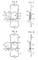
- Lens element 40 is piano-convex and is preferably oriented with its plane surface facing forward, in close adjacency with the plane surface of a movable lens element 42 having arm and pivot formations 17-18 as described for lens element 12 (Figs. 1 to 5).
- a bearing aperture 43 in lens 40 mounts one end of pivot 18, and a bearing aperture in a frame member 44 mounts the other end of pivot 18.
- Spacer posts or lugs 45 ⁇ 46 ⁇ 47 retain the central opening 48 of frame member 44 in register with the optical axis of lens 40 and serve as limit stops for the respective off-axis and on-axis positions of movable lens element 42, analogous to similar functions described for the embodiment of Figs. 1 to 5.
- Ears 28 on lens element 42 retain the axially-captured status when in the on-axis position, and magnetic element 30 in movable lens 42 enables selective surgically non-invasive actuation from one to the other of the two limiting positions of lens 42.
- Figs. 8 and 9 is very much like that of Figs. 6 and 7, except that in place of the fixed lens 40 is a fixed frame member 49 which is equipped by haptic means 41-41' and which may otherwise be generally as described for frame member 13 of Fig. 4, i.e., with a central circular opening 14, with a lateral arm projection 26, and with spaced connecting lugs 22-23-24 for positioning a second frame member 20 of the nature shown in Fig. 5; for clarity, frame member 20 is shown in Fig. 9 but has been omitted from Fig. 8.
- the movable lens element 42 of Figs. 8 and 9 is guided by and between frame members 20-49 and is non-invasively actuated via an imbedded magnetic element 30.
- Figs. 8 and 9 may serve the patient who already has a posterior-chamber implanted lens (as, for example, shown in Fig. 3 but without posts 15) and for whom it is desired to provide selectably extendable focal range, by reason of anterior-chamber implantation of the device of Figs. 8 and 9, with opening 14 centered on the pupillary axis Y.
- FIG. 10 and 11 exemplifies the invention in application to anterior-chamber mounting, of a frame member 60 via vaulted haptics 61-61' with reference to the stationary or scleral-ridge region of the anterior-chamber side of the iris.
- a movable lens element 62 includes a pivot pin 63 which derives bearing support from aligned apertures in frame member 60 and in an outer frame member 64, frame members 60-64 being held in axially spaced register by spacer posts or lugs 65 ⁇ 66 ⁇ 67.
- a "fixed" posterior lens element 68 derives axially aligned cantilevered support from frame member 60, via angularly spaced trans-iris positioning struts 69.
- Each of the struts will be understood to be L-shaped, with a radially inward leg portion anchored to frame member 60, and with an axially inward trans-iris portion anchored to lens element 68.
- Outward ear projections 70-71 on movable lens element 62 will be understood to axially restrain the on-axis position of element 62.
- the on-axis angular position is retained by a stop lug or pin 72 on one of the frame members 60-64, and the off-axis position is retained by lug 67, as will be understood.
- actuating structure for the described movable-lens configurations may be as simple as a polarized magnet embodied in a finger ring, it may to some users be more convenient to embody magnetic control in a spectacle frame, whether or not there are optical lens elements fitted to the spectacle frame.
- Such structure and its operation are shown in the simplified views of Figs. 12 and 13.
- a spectacle frame is seen to comprise a transverse member 80, with hinged ear pieces 81-81' at its ends; a suitably shaped central bridge formation 82 is comfortably adapted to the nose, and optional lens elements are suggested by phantom outlines 83-84.
- polarized magnets 85-86 are reversibly mounted to the spectacle frame, being shown pivotally mounted near the ends of member 80, and preferably a third such magnet 87 is similarly mounted in the bridge region of member 80.
- These magnets may be of any suitable shape, for example pinion-shaped and polarized along a diameter, but for schematic purposes these magnets are shown as bars, with pinion teeth, and polarized as suggested by N-S symbolism.
- a shiftable member 88 with rack teeth engaged to magnet-pinion teeth has an exposed actuable element 89 for selecting either the polarity relation shown or a 180°-reversed polarity configuration, as will be understood.
- the described spectacle frame with reversible magnets is shown in Fig. 13 to effect desired actuation of movable-lens elements 12 (in one eye's intraocular implantation) and 12' (in the other eye's intraocular implantation).
- the on-axis position of movable lens axis X registration with fixed-lens axis Y is inward, toward the nose, and the off-axis position is outward, toward the adjacent ear piece 81;
- the on-axis position of movable-lens axis X' registration with fixed-lens axis Y' is inward, toward the nose, the off-axis position being outward toward ear piece 81' and, therefore, in the displacement direction away from off-axis displacement of lens axis X for the left eye.
- Magnet inserts 30 in the respective movable-lens element 12-12' are polarized alike, as shown by N-S symbolism, the axis of polarization being transverse of the central line of symmetry of each element 12-12', i.e., through its pivot center 18 and the center of its magnet insert 30.
- the polarized orientation of outer magnets 85-86 should always be opposed to that of the central magnet 87. That being the case, for the relation shown in Fig. 13, the off-axis or outward-left position of lens element 12 is magnetically retained by proximity of the North-polarized end of magnet 85 and the South-polarized end of the involved insert 30. At the same time, the off-axis or outward-right position of lens element 12' is magnetically retained by proximity of the South-polarized end of magnet 86 and the North-polarized end of the involved insert 30. Also at the same time, the orientation of central magnet 87 is such as to present like poles to the nearest poles of elements 30, thus developing repel action for further assured retention of the off-axis positions of both movable lens elements 12-12'.
- the shift device 89 When it is desired to bring both movable lens elements into their on-axis positions of registration with the respective pupillary axes Y-Y', the shift device 89 is manually displaced, causing magnets 85-86-87 to 180°-reverse their polarized orientation.
- magnets 85-86-87 repel to develop clockwise torque about the pivot axis of movable element 12, resulting in its left-to-right displacement into the on-axis position of registration with axis Y; and upon reaching this on-axis position, the attraction of opposite poles at 30 and 87 serves to retain the on-axis position of element 12.
- the described invention will be seen to achieve all stated objects with basically simple and lightweight structure. And the principles of the invention are seen to be applicable to varied anterior, posterior, and trans-iris support, to suit the choice of the individual surgeon.
- the involved implantation technique need be no more difficult or complex than for conventional single-lens implantations. It will, of course, be understood that in the drawings it was necessary to show sizes, thicknesses and clearances withsome exaggeration, in order to permit identification of parts; for example, the displacement sweep of lens element 12 from one to the other of its positions is under the continuous guidance not only of the described pivot (18) action but also of surfaces of frame members 13-20 (Figs. 1 to 5), or of lens 40 and frame member 44 (Figs. 6, 7).
Landscapes
- Health & Medical Sciences (AREA)
- Ophthalmology & Optometry (AREA)
- Cardiology (AREA)
- Oral & Maxillofacial Surgery (AREA)
- Transplantation (AREA)
- Engineering & Computer Science (AREA)
- Biomedical Technology (AREA)
- Heart & Thoracic Surgery (AREA)
- Vascular Medicine (AREA)
- Life Sciences & Earth Sciences (AREA)
- Animal Behavior & Ethology (AREA)
- General Health & Medical Sciences (AREA)
- Public Health (AREA)
- Veterinary Medicine (AREA)
- Prostheses (AREA)
- Eyeglasses (AREA)
Claims (20)
Applications Claiming Priority (2)
| Application Number | Priority Date | Filing Date | Title |
|---|---|---|---|
| US06/368,409 US4435856A (en) | 1982-04-14 | 1982-04-14 | Bifocal intraocular lens structure and spectacle actuation frame |
| US368409 | 1999-08-05 |
Publications (2)
| Publication Number | Publication Date |
|---|---|
| EP0094158A1 EP0094158A1 (fr) | 1983-11-16 |
| EP0094158B1 true EP0094158B1 (fr) | 1987-01-14 |
Family
ID=23451083
Family Applications (1)
| Application Number | Title | Priority Date | Filing Date |
|---|---|---|---|
| EP83302121A Expired EP0094158B1 (fr) | 1982-04-14 | 1983-04-14 | Système de lentille intraoculaire bifocale |
Country Status (6)
| Country | Link |
|---|---|
| US (1) | US4435856A (fr) |
| EP (1) | EP0094158B1 (fr) |
| JP (1) | JPS58190439A (fr) |
| CA (1) | CA1190703A (fr) |
| DE (1) | DE3369064D1 (fr) |
| ZA (1) | ZA832544B (fr) |
Families Citing this family (117)
| Publication number | Priority date | Publication date | Assignee | Title |
|---|---|---|---|---|
| DE3332313A1 (de) * | 1983-09-07 | 1985-04-04 | Titmus Eurocon Kontaktlinsen GmbH, 8750 Aschaffenburg | Multifokale, insbesondere bifokale intraokulare kuenstliche augenlinse |
| US4636211A (en) * | 1984-03-13 | 1987-01-13 | Nielsen J Mchenry | Bifocal intra-ocular lens |
| EP0162573A3 (fr) * | 1984-04-17 | 1986-10-15 | Sanford D. Hecht | Implant oculaire |
| US4605409A (en) * | 1984-05-21 | 1986-08-12 | Kelman Charles D | Intraocular lens with miniature optic having expandable and contractible glare-reducing means |
| FI79619C (fi) * | 1984-12-31 | 1990-01-10 | Antti Vannas | Intraokulaer lins. |
| US4743254A (en) * | 1985-01-31 | 1988-05-10 | American Hospital Supply Company | Small incision intraocular lens |
| US4759762A (en) * | 1985-03-08 | 1988-07-26 | Grendahl Dennis T | Accommodating lens |
| US4666446A (en) * | 1986-05-06 | 1987-05-19 | Koziol Jeffrey E | Intraocular lens with converging and diverging optical portions |
| US5366500A (en) * | 1986-06-05 | 1994-11-22 | Richard T. Schneider | One-piece bifocal intraocular lens construction |
| US5192318A (en) * | 1986-06-05 | 1993-03-09 | Schneider Richard T | One-piece bifocal intraocular lens construction |
| US4759763A (en) * | 1986-11-03 | 1988-07-26 | Precision-Cosmet Co., Inc. | Foldable intraocular lens |
| US4753653A (en) * | 1986-11-03 | 1988-06-28 | Precision-Cosmet Co., Inc. | Foldable bifocal intraocular lens |
| JPS63106417U (fr) * | 1986-12-29 | 1988-07-09 | ||
| US4816031A (en) * | 1988-01-29 | 1989-03-28 | Pfoff David S | Intraocular lens system |
| US5089024A (en) * | 1988-04-19 | 1992-02-18 | Storz Instrument Company | Multi-focal intraocular lens |
| US4932966A (en) * | 1988-08-15 | 1990-06-12 | Storz Instrument Company | Accommodating intraocular lens |
| US5326347A (en) * | 1991-08-12 | 1994-07-05 | Cumming J Stuart | Intraocular implants |
| US5344448A (en) * | 1992-02-11 | 1994-09-06 | Schneider Richard T | Multi-focal intra-ocular implant |
| US5571177A (en) * | 1993-06-14 | 1996-11-05 | Allergan | IOL structured for post-operative re-positioning and method for post-operative IOL re-positioning |
| JP3352790B2 (ja) * | 1993-11-01 | 2002-12-03 | ▲桜▼井精技株式会社 | 眼内レンズの焦点位置調整方法とその装置 |
| DE4340205C1 (de) * | 1993-11-25 | 1995-04-20 | Dieter W Klaas | Intraokularlinse mit einer Akkomodationseinrichtung |
| US5549670A (en) * | 1995-05-09 | 1996-08-27 | Allergan, Inc. | IOL for reducing secondary opacification |
| US5693094A (en) | 1995-05-09 | 1997-12-02 | Allergan | IOL for reducing secondary opacification |
| US5800533A (en) * | 1996-03-18 | 1998-09-01 | Harry C. Eggleston | Adjustable intraocular lens implant with magnetic adjustment facilities |
| AU7282898A (en) * | 1998-04-30 | 1999-11-23 | Herrick Family Limited Partnership | Artificial lens including a multifocal lens system having eccentric axis and method |
| US6468306B1 (en) | 1998-05-29 | 2002-10-22 | Advanced Medical Optics, Inc | IOL for inhibiting cell growth and reducing glare |
| US6162249A (en) * | 1998-05-29 | 2000-12-19 | Allergan | IOI for inhibiting cell growth and reducing glare |
| US6884262B2 (en) * | 1998-05-29 | 2005-04-26 | Advanced Medical Optics, Inc. | Enhanced intraocular lens for reducing glare |
| US6066171A (en) * | 1998-06-01 | 2000-05-23 | Visioncare Ltd. | Intraocular lens with pivoting telescope |
| US20060238702A1 (en) | 1999-04-30 | 2006-10-26 | Advanced Medical Optics, Inc. | Ophthalmic lens combinations |
| US6228113B1 (en) | 2000-01-10 | 2001-05-08 | Board Of Supervisors Of Louisiana State University And Agricultural And Mechanical College | Intracorneal astigmatic onlay |
| US8062361B2 (en) * | 2001-01-25 | 2011-11-22 | Visiogen, Inc. | Accommodating intraocular lens system with aberration-enhanced performance |
| US6638305B2 (en) * | 2001-05-15 | 2003-10-28 | Advanced Medical Optics, Inc. | Monofocal intraocular lens convertible to multifocal intraocular lens |
| EP1399097A4 (fr) * | 2001-06-22 | 2005-04-27 | David Miller | Lentilles intraoculaires d'accommodation ameliorees |
| US20030060878A1 (en) | 2001-08-31 | 2003-03-27 | Shadduck John H. | Intraocular lens system and method for power adjustment |
| US7763069B2 (en) | 2002-01-14 | 2010-07-27 | Abbott Medical Optics Inc. | Accommodating intraocular lens with outer support structure |
| US8048155B2 (en) * | 2002-02-02 | 2011-11-01 | Powervision, Inc. | Intraocular implant devices |
| US7261737B2 (en) * | 2002-12-12 | 2007-08-28 | Powervision, Inc. | Accommodating intraocular lens system and method |
| US20070100445A1 (en) * | 2003-02-03 | 2007-05-03 | Shadduck John H | Intraocular lenses and business methods |
| US20050021139A1 (en) * | 2003-02-03 | 2005-01-27 | Shadduck John H. | Ophthalmic devices, methods of use and methods of fabrication |
| US6648741B2 (en) | 2002-03-14 | 2003-11-18 | Advanced Medical Optics, Inc. | Apparatus for protecting the edge geometry of an intraocular lens during glass bead polishing process |
| US7662180B2 (en) | 2002-12-05 | 2010-02-16 | Abbott Medical Optics Inc. | Accommodating intraocular lens and method of manufacture thereof |
| US8328869B2 (en) * | 2002-12-12 | 2012-12-11 | Powervision, Inc. | Accommodating intraocular lenses and methods of use |
| US8361145B2 (en) | 2002-12-12 | 2013-01-29 | Powervision, Inc. | Accommodating intraocular lens system having circumferential haptic support and method |
| US7438723B2 (en) * | 2002-12-12 | 2008-10-21 | Powervision, Inc. | Lens system and method for power adjustment using externally actuated micropumps |
| US7217288B2 (en) * | 2002-12-12 | 2007-05-15 | Powervision, Inc. | Accommodating intraocular lens having peripherally actuated deflectable surface and method |
| US7247168B2 (en) * | 2002-12-12 | 2007-07-24 | Powervision, Inc. | Accommodating intraocular lens system and method |
| US10835373B2 (en) | 2002-12-12 | 2020-11-17 | Alcon Inc. | Accommodating intraocular lenses and methods of use |
| US7637947B2 (en) * | 2002-12-12 | 2009-12-29 | Powervision, Inc. | Accommodating intraocular lens system having spherical aberration compensation and method |
| EP2559405A3 (fr) * | 2002-12-12 | 2013-06-26 | PowerVision, Inc. | Système de lentille intra-oculaire à accommodation |
| EP1599748A4 (fr) * | 2003-03-06 | 2007-10-24 | John H Shadduck | Lentille optique adaptative et procede de fabrication |
| FR2862524A1 (fr) * | 2003-11-21 | 2005-05-27 | Jacques Duvert | Implant oculaire pour la correction des defauts de la vision |
| EP1694252B1 (fr) | 2003-12-09 | 2017-08-09 | Abbott Medical Optics Inc. | Lentille intraoculaire pliable et procede de fabrication de celle-ci |
| US7615073B2 (en) | 2003-12-09 | 2009-11-10 | Advanced Medical Optics, Inc. | Foldable intraocular lens and method of making |
| US20050131535A1 (en) | 2003-12-15 | 2005-06-16 | Randall Woods | Intraocular lens implant having posterior bendable optic |
| NL1025622C2 (nl) * | 2004-03-03 | 2005-09-07 | Accolens Internat B V | Twee tezamen een lens vormende optische elementen met variabele optische sterkte voor gebruik als intra-oculaire lens. |
| WO2006014738A2 (fr) * | 2004-07-22 | 2006-02-09 | Cornell Research Foundation, Inc. | Lentille intraoculaire d'accommodation et modes d'utilisation associes |
| US9872763B2 (en) | 2004-10-22 | 2018-01-23 | Powervision, Inc. | Accommodating intraocular lenses |
| NL1029037C2 (nl) * | 2005-05-13 | 2006-11-14 | Akkolens Int Bv | Verbeterde intra-oculaire kunstlens met variable optische sterkte. |
| US20070088433A1 (en) * | 2005-10-17 | 2007-04-19 | Powervision | Accommodating intraocular lens system utilizing direct force transfer from zonules and method of use |
| CA2673388C (fr) | 2006-12-22 | 2015-11-24 | Amo Groningen B.V. | Lentille intraoculaire d'accommodation, systeme de lentille et structure pour lentille |
| US20080161914A1 (en) | 2006-12-29 | 2008-07-03 | Advanced Medical Optics, Inc. | Pre-stressed haptic for accommodating intraocular lens |
| US20080306587A1 (en) * | 2007-02-21 | 2008-12-11 | Jingjong Your | Lens Material and Methods of Curing with UV Light |
| US8158712B2 (en) * | 2007-02-21 | 2012-04-17 | Powervision, Inc. | Polymeric materials suitable for ophthalmic devices and methods of manufacture |
| EP2647353B1 (fr) * | 2007-07-23 | 2014-12-31 | PowerVision, Inc. | Système de mise en place de lentille |
| AU2008279167B2 (en) * | 2007-07-23 | 2014-10-09 | Alcon Inc. | Post-implant lens power modification |
| US8314927B2 (en) | 2007-07-23 | 2012-11-20 | Powervision, Inc. | Systems and methods for testing intraocular lenses |
| JP5346022B2 (ja) | 2007-07-23 | 2013-11-20 | パワーヴィジョン・インコーポレーテッド | 調節眼内レンズおよび使用方法 |
| US8968396B2 (en) | 2007-07-23 | 2015-03-03 | Powervision, Inc. | Intraocular lens delivery systems and methods of use |
| ES2711908T3 (es) * | 2007-10-15 | 2019-05-08 | Akkolens Int B V | Lente intraocular acomodativa ajustable y medios de posicionamiento |
| US8034108B2 (en) | 2008-03-28 | 2011-10-11 | Abbott Medical Optics Inc. | Intraocular lens having a haptic that includes a cap |
| US20100082017A1 (en) | 2008-09-26 | 2010-04-01 | Advanced Medical Optics, Inc. | Laser modification of intraocular lens |
| US10299913B2 (en) | 2009-01-09 | 2019-05-28 | Powervision, Inc. | Accommodating intraocular lenses and methods of use |
| AU2010203427B2 (en) * | 2009-01-09 | 2017-05-18 | Alcon Inc. | Intraocular lenses and methods of accounting for capsule size variability and post-implant changes in the eye |
| AU2010266022B2 (en) | 2009-06-26 | 2015-04-23 | Johnson & Johnson Surgical Vision, Inc. | Accommodating intraocular lenses |
| AU2010279561B2 (en) | 2009-08-03 | 2014-11-27 | Johnson & Johnson Surgical Vision, Inc. | Intraocular lens for providing accomodative vision |
| EP2473138A4 (fr) * | 2009-08-31 | 2017-08-16 | PowerVision, Inc. | Estimation de la taille de la capsule du cristallin |
| US9278026B2 (en) | 2009-09-30 | 2016-03-08 | Abbott Medical Optics Inc. | Capsular membrane treatments to increase accommodative amplitude |
| US9445889B2 (en) | 2009-09-30 | 2016-09-20 | Abbott Medical Optics Inc. | Capsular membrane implants to increase accommodative amplitude |
| GB2476480B (en) * | 2009-12-22 | 2013-04-03 | Marwan Ghabra | Intraocular implant with a fixed and a pivoting lens |
| EP3263574B1 (fr) * | 2010-02-23 | 2019-04-03 | PowerVision, Inc. | Lentille intraoculaire à accomodation |
| WO2012006186A2 (fr) * | 2010-06-29 | 2012-01-12 | The Arizona Board Of Regents On Behalf Of The University Of Arizona | Lentille intraoculaire accommodative comportant un matériau déformable |
| WO2012006616A2 (fr) | 2010-07-09 | 2012-01-12 | Powervision, Inc. | Dispositif de pose de lentilles intraoculaires et leurs procédés d'utilisation |
| US9005200B2 (en) | 2010-09-30 | 2015-04-14 | Covidien Lp | Vessel sealing instrument |
| FR2966340A1 (fr) * | 2010-10-20 | 2012-04-27 | Jacques Duvert | Implant artificiel intra-oculaire pour la correction de tous les defauts de vision de l'oeil et supprimer les lunettes de vue |
| EP3928744A1 (fr) | 2011-03-24 | 2021-12-29 | Alcon Inc. | Systèmes de chargement de lentille intraoculaire et procédés d'utilisation |
| US10433949B2 (en) | 2011-11-08 | 2019-10-08 | Powervision, Inc. | Accommodating intraocular lenses |
| US9364319B2 (en) | 2012-09-25 | 2016-06-14 | Valdemar Portney | Refractive-diffractive switchable optical element |
| WO2013109315A2 (fr) * | 2012-01-18 | 2013-07-25 | Valdemar Portney | Élément optique commutable réfractant-diffractant |
| EP2806828B1 (fr) | 2012-01-24 | 2021-07-21 | The Regents of The University of Colorado, A Body Corporate | Conceptions de lentilles intraoculaires modulaires et procédés s'y rapportant |
| US10080648B2 (en) | 2012-01-24 | 2018-09-25 | Clarvista Medical, Inc. | Modular intraocular lens designs, tools and methods |
| US10028824B2 (en) | 2012-01-24 | 2018-07-24 | Clarvista Medical, Inc. | Modular intraocular lens designs, tools and methods |
| US9364316B1 (en) | 2012-01-24 | 2016-06-14 | Clarvista Medical, Inc. | Modular intraocular lens designs, tools and methods |
| US8900300B1 (en) | 2012-02-22 | 2014-12-02 | Omega Ophthalmics Llc | Prosthetic capsular bag and method of inserting the same |
| CA2869471C (fr) | 2012-04-05 | 2021-07-20 | Fisher & Paykel Healthcare Limited | Appareil d'assistance respiratoire |
| US9554891B2 (en) | 2013-03-14 | 2017-01-31 | Amo Groningen B.V. | Apparatus, system, and method for providing an implantable ring for altering a shape of the cornea |
| EP2967842B1 (fr) | 2013-03-15 | 2020-11-04 | Alcon Inc. | Procede de reconfiguration d'une lentille intra-oculaire en vue de sa livraison a un dispositif de livraison |
| AU2015219461B2 (en) | 2014-02-18 | 2019-10-31 | Alcon Inc. | Modular intraocular lens designs, tools and methods |
| WO2015183107A1 (fr) | 2014-05-27 | 2015-12-03 | Fisher & Paykel Healthcare Limited | Mélange et mesure de gaz pour un dispositif médical |
| AU2015277207B2 (en) * | 2014-06-19 | 2018-03-29 | Omega Ophthalmics Llc | Prosthetic capsular devices, systems, and methods |
| EP3250152B1 (fr) | 2015-01-30 | 2025-03-12 | Alcon Inc. | Inserteur pour insertion d'une base et d'une lentille intraoculaire modulaire dans un oeil |
| US9358103B1 (en) | 2015-02-10 | 2016-06-07 | Omega Ophthalmics Llc | Prosthetic capsular devices, systems, and methods |
| JP6839100B2 (ja) | 2015-06-10 | 2021-03-03 | アルコン インコーポレイティド | 眼内レンズ材料及び部材 |
| CN108348327B (zh) | 2015-11-04 | 2021-10-01 | 克拉维斯塔医疗有限公司 | 模块化人工晶状体设计、工具和方法 |
| CA3001477A1 (fr) | 2015-11-06 | 2017-05-11 | Alcon Inc. | Lentilles intraoculaires d'accommodation et procedes de fabrication |
| CN114796778B (zh) | 2015-12-02 | 2026-04-03 | 费雪派克医疗保健有限公司 | 流量治疗设备的流动路径感测 |
| US11045309B2 (en) | 2016-05-05 | 2021-06-29 | The Regents Of The University Of Colorado | Intraocular lens designs for improved stability |
| US9993336B2 (en) | 2016-06-06 | 2018-06-12 | Omega Ophthalmics Llc | Prosthetic capsular devices, systems, and methods |
| WO2018075932A1 (fr) | 2016-10-21 | 2018-04-26 | Omega Ophthalmics Llc | Dispositifs capsulaires prothétiques, systèmes et procédés |
| US11382736B2 (en) | 2017-06-27 | 2022-07-12 | Alcon Inc. | Injector, intraocular lens system, and related methods |
| AU2018330604A1 (en) | 2017-09-11 | 2020-04-02 | Amo Groningen B.V. | Methods and apparatuses to increase intraocular lenses positional stability |
| AU2019249216B2 (en) | 2018-04-06 | 2024-07-18 | Omega Ophthalmics Llc | Prosthetic capsular devices, systems, and methods |
| RU191902U1 (ru) * | 2019-06-10 | 2019-08-28 | Вероника Евгеньевна Горячкина | Очки разборные |
| CN120938665A (zh) | 2019-10-04 | 2025-11-14 | 爱尔康公司 | 可调节眼内透镜及术后调节眼内透镜的方法 |
| WO2022082170A1 (fr) | 2020-10-12 | 2022-04-21 | Omega Ophthalmics Llc | Dispositifs capsulaires prothétiques, systèmes et procédés |
| BR112023018612A2 (pt) | 2021-04-06 | 2023-10-24 | Alcon Inc | Aparelho, sistemas e métodos para avaliar objetivamente a acomodação em um olho |
| US11357620B1 (en) | 2021-09-10 | 2022-06-14 | California LASIK & Eye, Inc. | Exchangeable optics and therapeutics |
Family Cites Families (12)
| Publication number | Priority date | Publication date | Assignee | Title |
|---|---|---|---|---|
| US3752567A (en) | 1971-07-01 | 1973-08-14 | K Broadhurst | Eyeglasses having interchangeable colored lenses |
| US4010496A (en) | 1975-10-01 | 1977-03-08 | Neefe Charles W | Bifocal lens which positions within the anterior chamber |
| US4056855A (en) | 1976-04-07 | 1977-11-08 | Charles Kelman | Intraocular lens and method of implanting same |
| US4073014A (en) | 1976-05-28 | 1978-02-14 | Stanley Poler | Intra-ocular lens |
| US4074368A (en) | 1976-09-08 | 1978-02-21 | Said Chauncey F. Levy, Jr., By Said Richard J. Pegis | Intraocular lens with high magnification |
| US4124905A (en) * | 1976-10-29 | 1978-11-14 | Bausch & Lomb Incorporated | Artificial intraocular lens system |
| US4187006A (en) | 1978-07-26 | 1980-02-05 | Premier Athletic Products Corp. | Flip-down sunglasses |
| FR2465461A1 (fr) | 1979-04-23 | 1981-03-27 | Buget Bernard | Mensurateur optique de la position de l'axe visuel |
| EP0024126A1 (fr) | 1979-07-26 | 1981-02-25 | David Peter Choyce | Lentille intra-oculaire pour l'implantation dans la chambre antérieure de l'oeil, traitable en autoclave |
| US4257130A (en) | 1979-08-27 | 1981-03-24 | Bayers Jon Herbert | Intraocular lens mechanism |
| US4298996A (en) | 1980-07-23 | 1981-11-10 | Barnet Ronald W | Magnetic retention system for intraocular lens |
| US4366582A (en) | 1980-12-01 | 1983-01-04 | Faulkner Gerald D | Posterior chamber intraocular lens |
-
1982
- 1982-04-14 US US06/368,409 patent/US4435856A/en not_active Expired - Fee Related
-
1983
- 1983-04-12 ZA ZA832544A patent/ZA832544B/xx unknown
- 1983-04-13 CA CA000425784A patent/CA1190703A/fr not_active Expired
- 1983-04-14 JP JP58066294A patent/JPS58190439A/ja active Pending
- 1983-04-14 EP EP83302121A patent/EP0094158B1/fr not_active Expired
- 1983-04-14 DE DE8383302121T patent/DE3369064D1/de not_active Expired
Also Published As
| Publication number | Publication date |
|---|---|
| US4435856A (en) | 1984-03-13 |
| DE3369064D1 (en) | 1987-02-19 |
| EP0094158A1 (fr) | 1983-11-16 |
| JPS58190439A (ja) | 1983-11-07 |
| CA1190703A (fr) | 1985-07-23 |
| ZA832544B (en) | 1983-12-28 |
Similar Documents
| Publication | Publication Date | Title |
|---|---|---|
| EP0094158B1 (fr) | Système de lentille intraoculaire bifocale | |
| CA2155428C (fr) | Element d'insertion intraoculaire pour implantation dans l'oeil | |
| US4946469A (en) | Intraocular lens | |
| US5800533A (en) | Adjustable intraocular lens implant with magnetic adjustment facilities | |
| CA1086452A (fr) | Lentilles intraoculaires | |
| JP4113674B2 (ja) | 遠近調節性眼内レンズ | |
| US5047051A (en) | Intraocular lens with haptic anchor plate | |
| EP0092552B1 (fr) | Lentille intraoculaire pour patients presentant une degeneration retinienne centrale | |
| GB2050173A (en) | Artificial intraocular lens and method of implanting same | |
| EP0162573A2 (fr) | Implant oculaire | |
| JPH02126847A (ja) | 眼内レンズ | |
| WO2003000154A3 (fr) | Lentilles intraoculaires d'accommodation ameliorees | |
| EP3131501B1 (fr) | Lentille intraoculaire secondaire ayant une partie optique coaxiale grossissante | |
| KR20020064874A (ko) | 눈 적응능을 보유하는 안내 렌즈 이식물 | |
| KR20090041390A (ko) | 원근 조절용 다구면 안내 렌즈 | |
| KR20220110477A (ko) | 가변 초점 거리 렌즈 및 이를 포함하는 안경 | |
| WO1992003989A1 (fr) | Lentille intraoculaire a puissance variable et correction d'astigmatisme | |
| EP0650704A1 (fr) | Lentille intraoculaire à focalisation variable | |
| JPH09294754A (ja) | 眼内レンズの構造及び焦点距離調整方法 | |
| US20020151973A1 (en) | Intraocular lens | |
| US10575943B2 (en) | Vision correction systems and methods for using an intraocular lens enclosed in an inner capsulated bag | |
| EP0587565B1 (fr) | Lentille intraoculaire pourvue d'une plaquette d'ancrage haptique | |
| US20210353406A1 (en) | Accommodative Functionality for Artificial Capsule Platform | |
| CA3163961A1 (fr) | Lentille intraoculaire en plusieurs parties avec mecanisme de verrouillage | |
| EP1275354A1 (fr) | Lentille intraoculaire |
Legal Events
| Date | Code | Title | Description |
|---|---|---|---|
| PUAI | Public reference made under article 153(3) epc to a published international application that has entered the european phase |
Free format text: ORIGINAL CODE: 0009012 |
|
| AK | Designated contracting states |
Designated state(s): BE CH DE FR GB IT LI NL |
|
| 17P | Request for examination filed |
Effective date: 19840427 |
|
| ITF | It: translation for a ep patent filed | ||
| GRAA | (expected) grant |
Free format text: ORIGINAL CODE: 0009210 |
|
| AK | Designated contracting states |
Kind code of ref document: B1 Designated state(s): BE CH DE FR GB IT LI NL |
|
| REF | Corresponds to: |
Ref document number: 3369064 Country of ref document: DE Date of ref document: 19870219 |
|
| ET | Fr: translation filed | ||
| PLBE | No opposition filed within time limit |
Free format text: ORIGINAL CODE: 0009261 |
|
| STAA | Information on the status of an ep patent application or granted ep patent |
Free format text: STATUS: NO OPPOSITION FILED WITHIN TIME LIMIT |
|
| 26N | No opposition filed | ||
| PGFP | Annual fee paid to national office [announced via postgrant information from national office to epo] |
Ref country code: GB Payment date: 19910410 Year of fee payment: 9 |
|
| PGFP | Annual fee paid to national office [announced via postgrant information from national office to epo] |
Ref country code: FR Payment date: 19910426 Year of fee payment: 9 |
|
| ITTA | It: last paid annual fee | ||
| PGFP | Annual fee paid to national office [announced via postgrant information from national office to epo] |
Ref country code: NL Payment date: 19910430 Year of fee payment: 9 |
|
| PGFP | Annual fee paid to national office [announced via postgrant information from national office to epo] |
Ref country code: CH Payment date: 19910507 Year of fee payment: 9 |
|
| PGFP | Annual fee paid to national office [announced via postgrant information from national office to epo] |
Ref country code: DE Payment date: 19910531 Year of fee payment: 9 |
|
| PGFP | Annual fee paid to national office [announced via postgrant information from national office to epo] |
Ref country code: BE Payment date: 19910603 Year of fee payment: 9 |
|
| PG25 | Lapsed in a contracting state [announced via postgrant information from national office to epo] |
Ref country code: GB Effective date: 19920414 |
|
| PG25 | Lapsed in a contracting state [announced via postgrant information from national office to epo] |
Ref country code: LI Effective date: 19920430 Ref country code: CH Effective date: 19920430 Ref country code: BE Effective date: 19920430 |
|
| BERE | Be: lapsed |
Owner name: L'ESPERANCE FRANCIS A. Effective date: 19920430 |
|
| PG25 | Lapsed in a contracting state [announced via postgrant information from national office to epo] |
Ref country code: NL Effective date: 19921101 |
|
| GBPC | Gb: european patent ceased through non-payment of renewal fee | ||
| NLV4 | Nl: lapsed or anulled due to non-payment of the annual fee | ||
| PG25 | Lapsed in a contracting state [announced via postgrant information from national office to epo] |
Ref country code: FR Effective date: 19921230 |
|
| REG | Reference to a national code |
Ref country code: CH Ref legal event code: PL |
|
| PG25 | Lapsed in a contracting state [announced via postgrant information from national office to epo] |
Ref country code: DE Effective date: 19930101 |
|
| REG | Reference to a national code |
Ref country code: FR Ref legal event code: ST |