EP0094207A2 - Enregistreur à bande vidéo avec commande continue d'alignement pendant le mode d'édition - Google Patents
Enregistreur à bande vidéo avec commande continue d'alignement pendant le mode d'édition Download PDFInfo
- Publication number
- EP0094207A2 EP0094207A2 EP83302536A EP83302536A EP0094207A2 EP 0094207 A2 EP0094207 A2 EP 0094207A2 EP 83302536 A EP83302536 A EP 83302536A EP 83302536 A EP83302536 A EP 83302536A EP 0094207 A2 EP0094207 A2 EP 0094207A2
- Authority
- EP
- European Patent Office
- Prior art keywords
- track
- signal
- series
- gating pulses
- heads
- Prior art date
- Legal status (The legal status is an assumption and is not a legal conclusion. Google has not performed a legal analysis and makes no representation as to the accuracy of the status listed.)
- Granted
Links
Images


Classifications
-
- G—PHYSICS
- G11—INFORMATION STORAGE
- G11B—INFORMATION STORAGE BASED ON RELATIVE MOVEMENT BETWEEN RECORD CARRIER AND TRANSDUCER
- G11B15/00—Driving, starting or stopping record carriers of filamentary or web form; Driving both such record carriers and heads; Guiding such record carriers or containers therefor; Control thereof; Control of operating function
- G11B15/18—Driving; Starting; Stopping; Arrangements for control or regulation thereof
- G11B15/46—Controlling, regulating, or indicating speed
- G11B15/467—Controlling, regulating, or indicating speed in arrangements for recording or reproducing wherein both record carriers and heads are driven
- G11B15/4673—Controlling, regulating, or indicating speed in arrangements for recording or reproducing wherein both record carriers and heads are driven by controlling the speed of the tape while the head is rotating
- G11B15/4675—Controlling, regulating, or indicating speed in arrangements for recording or reproducing wherein both record carriers and heads are driven by controlling the speed of the tape while the head is rotating with provision for information tracking
- G11B15/4676—Controlling, regulating, or indicating speed in arrangements for recording or reproducing wherein both record carriers and heads are driven by controlling the speed of the tape while the head is rotating with provision for information tracking using signals recorded in tracks disposed in parallel with the scanning direction
- G11B15/4677—Controlling, regulating, or indicating speed in arrangements for recording or reproducing wherein both record carriers and heads are driven by controlling the speed of the tape while the head is rotating with provision for information tracking using signals recorded in tracks disposed in parallel with the scanning direction using auxiliary signals, i.e. pilot signals
- G11B15/4678—Controlling, regulating, or indicating speed in arrangements for recording or reproducing wherein both record carriers and heads are driven by controlling the speed of the tape while the head is rotating with provision for information tracking using signals recorded in tracks disposed in parallel with the scanning direction using auxiliary signals, i.e. pilot signals superimposed on the main signal track
-
- G—PHYSICS
- G11—INFORMATION STORAGE
- G11B—INFORMATION STORAGE BASED ON RELATIVE MOVEMENT BETWEEN RECORD CARRIER AND TRANSDUCER
- G11B15/00—Driving, starting or stopping record carriers of filamentary or web form; Driving both such record carriers and heads; Guiding such record carriers or containers therefor; Control thereof; Control of operating function
- G11B15/18—Driving; Starting; Stopping; Arrangements for control or regulation thereof
- G11B15/1808—Driving of both record carrier and head
- G11B15/1875—Driving of both record carrier and head adaptations for special effects or editing
-
- G—PHYSICS
- G11—INFORMATION STORAGE
- G11B—INFORMATION STORAGE BASED ON RELATIVE MOVEMENT BETWEEN RECORD CARRIER AND TRANSDUCER
- G11B27/00—Editing; Indexing; Addressing; Timing or synchronising; Monitoring; Measuring tape travel
- G11B27/02—Editing, e.g. varying the order of information signals recorded on, or reproduced from, record carriers
- G11B27/022—Electronic editing of analogue information signals, e.g. audio or video signals
- G11B27/029—Insert-editing
-
- G—PHYSICS
- G11—INFORMATION STORAGE
- G11B—INFORMATION STORAGE BASED ON RELATIVE MOVEMENT BETWEEN RECORD CARRIER AND TRANSDUCER
- G11B5/00—Recording by magnetisation or demagnetisation of a record carrier; Reproducing by magnetic means; Record carriers therefor
- G11B5/48—Disposition or mounting of heads or head supports relative to record carriers ; arrangements of heads, e.g. for scanning the record carrier to increase the relative speed
- G11B5/58—Disposition or mounting of heads or head supports relative to record carriers ; arrangements of heads, e.g. for scanning the record carrier to increase the relative speed with provision for moving the head for the purpose of maintaining alignment of the head relative to the record carrier during transducing operation, e.g. to compensate for surface irregularities of the latter or for track following
- G11B5/584—Disposition or mounting of heads or head supports relative to record carriers ; arrangements of heads, e.g. for scanning the record carrier to increase the relative speed with provision for moving the head for the purpose of maintaining alignment of the head relative to the record carrier during transducing operation, e.g. to compensate for surface irregularities of the latter or for track following for track following on tapes
- G11B5/588—Disposition or mounting of heads or head supports relative to record carriers ; arrangements of heads, e.g. for scanning the record carrier to increase the relative speed with provision for moving the head for the purpose of maintaining alignment of the head relative to the record carrier during transducing operation, e.g. to compensate for surface irregularities of the latter or for track following for track following on tapes by controlling the position of the rotating heads
-
- G—PHYSICS
- G11—INFORMATION STORAGE
- G11B—INFORMATION STORAGE BASED ON RELATIVE MOVEMENT BETWEEN RECORD CARRIER AND TRANSDUCER
- G11B2220/00—Record carriers by type
- G11B2220/90—Tape-like record carriers
-
- G—PHYSICS
- G11—INFORMATION STORAGE
- G11B—INFORMATION STORAGE BASED ON RELATIVE MOVEMENT BETWEEN RECORD CARRIER AND TRANSDUCER
- G11B27/00—Editing; Indexing; Addressing; Timing or synchronising; Monitoring; Measuring tape travel
- G11B27/02—Editing, e.g. varying the order of information signals recorded on, or reproduced from, record carriers
- G11B27/022—Electronic editing of analogue information signals, e.g. audio or video signals
- G11B27/024—Electronic editing of analogue information signals, e.g. audio or video signals on tapes
Definitions
- the present invention relates generally to video recorders, and in particular to a video tape recording and reproducing apparatus having an edit mode for inserting a new program into a prerecorded material without causing disturbances during transitions at the boundaries between different programs.
- a stationary head is employed for recording a tracking signal along an edge of videotape in synchronism with the picture field of the video signal so that the recorded tracking signal corresponds in position to each oblique track.
- the tracking signal is detected to generate a reference phase with which the speed of revolution of the rotary heads is compared to detect a difference between them.
- the transport speed of the tape is controlled in response to the detected phase difference so that the video heads is precisely kept on track.
- the video recorder which has recently been developed employs a pilot signal which is recorded through the rotary heads on each track with the video signal to identify the track.
- the video recorder of this type still suffers from the above-mentioned difficulty.
- the present invention contemplates to exploit the excellent tracking capability of the video tape recorder of the type wherein pilot signals are recorded on video tracks.
- the operational mode of rotary heads is alternately switched between playback and recording in synchronism with each half revolution of the video head cylinder.
- the tape is wound on the cylinder so that it extends over an arc greater than a semicircle.
- the video signal is recorded in a major portion of the track while the pilot signal is recorded over the full length of the track.
- the alternate switching of video heads is initiated in response to an insert command signal when a desired point of a prerecorded program is reached.
- the tape extends over an arc greater than 180 degrees
- the other head when each one of the heads is recording a video signal in a major portion of a given track, the other head is operating in a playback mode while tracing a minor portion of a subsequent track where a pilot signal is present. Therefore, if one head is tracing the first track of an "insert" program, the other head is tracing that portion of subsequent track where the pilot signal of the prerecorded program is present. This pilot signal is used to generate a tracking control signal with which tape sped is controlled.
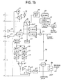
- a video tape recording/playback apparatus constructed according to a first embodiment of the invention.
- the apparatus includes a plurality of mode selecting switches 19, 20 and 43 having recording- and playback-mode positions marked R and P, respectively, and a plurality of "insert" mode switches 81 to 89 each having normally closed contacts in which they are positioned during normal recording and playback modes and normally open contacts in which they are positioned during insert modes.
- a record/playback control signal is applied from a terminal 6 through switches 83, 84, 85 to switches 19, 20, 43, respectively, to control their switched positions.
- Video tansducer heads A and B are mounted in diametrically opposite positions of a rotary cylinder 1 which spins at high speeds about an axis tilted to the direction of movement of a videotape 2.
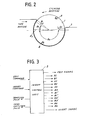
- the tape 2 is wound on that portion of the cylinder 1 that extends over an arc greater than 180 degrees as shown in Fig. 2 so that the video heads A and B are simultaneously brought into contact with the tape 2.
- Video and audio signals are recorded on that area of tape 2 that contacts the cylinder 1 and the extent of this contact area defines the length of the recording track. As illustrated in Fig. 2, this contact area, or track, is divided into five angular sections designated 91 to e5, with ⁇ 4 being equal to 180 degrees where the video signal of a field interval is recorded.
- the angular sections ⁇ 3 and 95 are overlapping areas where video signals of adjacent fields are recorded.
- the angular sections el and 62 are areas where a preamble code and a digitized audio signal are respectively recorded.
- an insert control circuit 3 is included, which as schematrically shown in Fig. 3, generates an edit command signal issued in preparation of an insert command, an insert signal, and various gating pulses Al-A4, Bl-B4, Al', A3', Bl' and B3', and pulses forswitching video heads and sampling tracking control signal for storage.
- a composite color video signal, aplied at an input terminal 4, is fed to a luminance or Y-signal processor 8 and a chrominance processor 9.
- the luminance comonent of the input video signal is frequency modulated in the processor 8 and the chrominance component is modulated upon a lower frequency carrier and multiplexed with the frequency-modulated luminance component in an adder 10 and fed to gates 11 and 12 and passed therethrough in response to gating pulses Al and Bl, respectively.
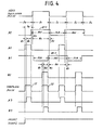
- the gating pulses Al and Bl are of identical rectangular waveform with a pulse duration slightly longer than the field interval of video signal so that it extends over a total angular sections e3, e4 and O5, but shifted in phase with each other by one field interval.
- An audio input singal, aplied to an input terminal 5, is converted to a digital signal by an encoding circuit which includes an analog-to-digital converter 22, a parity generator 23, a compressor 24 and a modulator 25.
- the AD converter 22 smaples the audio signal at a rate of two samples per picture line period and translates the sampled value into a 10-bit code.
- a parity bit or bits are added to the 10-bit coe in the parity generator 23.
- the compressosr 24 has a pair of identical read-wrie memories addressed alternately to write the digitized audio information in response to the field interval, or half revolution of the cylinder 1 and addressed alternately to read the stored information at a rate which is typically 20 times higher than the writing rate so that the digitized audio signal is compressed in time axis into a group of closely spaced apart pulses, or digital sample.
- the digital sample is modulated upon a carrier using a known modified frequency modulation technique which reduces the amount of DC component to make the signal suitable for recording on magnetic tapes.
- the modulated digial sample is aplied to gates 26 and 27 and passes therethrough in resonse to gating pulses A2 and B2 which are applied through insert mode switches 81 and 82, respectively, to adders 13 and 14 during normal recording modes.
- the gating pulses A2 and B2 has a duration equal to a total of 61 and e2 as shown in Fig. 4, and a phase difference of one field interval relative to each other.
- the trailing edges of the pulses A2 and B2 coincide with the leading edges of the gating pulses Al and Bl.
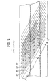
- the total duration of pulses Al and A2 equals the amount of time the video head A takes to scan along each of a plurality of oblique tracks marked a in Fig. 5.
- the total duration of pulses Bl and B2 equals the amount of time the video head B takes to scan along each of tracks b which appear alternately with and closely spaced from the tracks a.
- the digital sample is passed alternately ghrough gates 26 adn 27 and combined with the multiplexed luminance and chrominance signals.
- the combined video and audio signals are further combined with pilot signals.
- the pilot signals are derived from a circuit including a sync separator 44, a phase-locked loop 45 and freqeuncy dividers 46 to 49, an electronic rotary switch 50, an address decoder 51 and a low-pass filter 52.
- the sync separator 44 takes its input through the mode select swich 43 from the video input terminal 4 to extract and feed horizontal sync pulses to the phase-locked loop 45 where the line frequency is multiplied by an integer N and phase-locked at a frequency N x f H , where f H represents the line frequency.
- the decoder 51 derives a binary switching signal from head switching pulse, which is generated at each half revolution of the video heads, and applies it to the rotary switch 50 to sequentially feed the pilot signals f 1 to f 4 through the low-pass filter 52 to adders 15 and 16 to be combined with the outputs of the adders 13 and 14, respectively.
- the outputs of the adders 15 and 16 are fed through recording amplifiers 17 and 18 to the video heads A and B through mode select switches 19 and 20. Pilot signals f l to f 4 are sequentially recorded on tracks a and b respectively by heads A and B as shown in Fig. 5.
- the recorded information is derived alternately from heads A and B and intensified by playback amplifiers 28 and 29 (Fig. lb).
- the outputs of the amplifiers 28 and 29 are applied to gates 31 and 32 and passed to an adder 36 in response to gating pulses A3 and B3, respectively, each having a duration ⁇ 2 as shown in Fig. 4 so that the audio information recorded on the track segment ⁇ 2 is extracted.
- the digital signal from the adder 36 is processed by a pulse detector 37 into a signal having sharply defined edges and the necessary discrete levels for decoding.
- a demodulator 38 converts the output of the pulse detector 37 into a non-return-to-zero (NRZ) signal which is fed to an error collector 39 and thence to a time expansion circuit 40 whose function is to expand the time axis of the compressed signal by writing the signal alternately into one of two memories and reading the stored information at a rate reciprocal to the compression ratio.
- the time-expanded digital signal is applied to a digital-to-analog converter 41 to recover the original analog audio signal.
- the outputs of the amplifiers 28 and 29 are also applied to an electronic switch 30 which responds to head switching pulses by alternately coupling the video signals sequentially detected video signals to luminance and chrominance proccessors 33 and 34 whose outputs are combined in an adder 73 and delivered on the one hand to an output terminal 35 and on the other hand through a line 74 and the playback position of the mode selecting switch 43 to the sync separator 44 to serve as a source of reference pilot signals.
- the reference pilot signals f l to f 4 are generated as in recording modes and supplied from low-pass filter 52 through a line 75 to the first input of a balanced modulator 54.
- the output of the switch 30 is further coupled through an "insert mode" switch 87 to a low-pass filter 53 which passes the signals having a frequency lower than 10.5 f H to extract the pilot signals detected from the videotape. Therefore, the pilot signals f l , f 2 , f 3 and f 4 are derived recyclically in this order from the low-pass filter 53. This recyclic sequence of pilot signals is applied to the second input of the balanced modulator 54.
- Tracking control operation now commences. It is noted from Fig. 5 that there is a frequency difference f H between pilot signals derived from the 94 areas of tracks al and bl, while there is a frequency difference 3f H between pilot signals derived from the ⁇ 4 areas of tracks bl and a2. Therefore, for any given track a there is a frequency difference 3f H with respect to its leftside track and there is a frequency difference f H with respect to its rightside track. However, in respect of tracks b there is a frequency difference f H with respect to their leftside and there is a frequency difference 3f H with respect to their rightside track.
- Pilot signals on adjacent tracks are also picked up by video heads with a lesser magnitude than that derived from the center track and fed to the low-pass filter 53. If the frequency of the reproduced pilot signal coincides with a reference frequency supplied from the low-pass filter 52, the balanced modulator 54 will generate two signals having beat frequencies f H and 3f H which are detected respectively by band-pass filters 55 and 56 and detectors 57 and 58. Low-pass filters 59 and 60 extract the dc components of the signals from the detectors 57, 58, the dc components being applied to a differential amplifier 61 to detect the relative magnitude of the two beat frequency signals.
- the differential amplifier 61 If the head laterally deviates from a given track, one of the beat frequency signals becomes greater than the other and the differential amplifier 61 generates a corresponding differential output, or tracking control signal.
- the tracking control signal is applied on the one hand to the A position of an electronic switch 63 and on the other through an inverter 62 to the B position of the switch 63.
- the switch 63 responds to a head switching pulse by coupling its output to the A position when the head A is tracing a track a and coupling it to the B position when the head B is on a track b.
- the inverter 63 reverses the polarity of the differential signal whenever it is derived from tracks b since their beat frequency relationships are in reverse to those of tracks a as described above.
- the user viewing a television monitor, issues an insert command signal to the control unit 3 to provide an "insert" signal, Fig. 4, to switches 81-85, 88 and 89 when a desired point is reached in the displayed prerecorded program.
- the operation of switches 81 and 82 disables the digital audio signals from the external source to leave the prerecorded audio signals undisturbed.
- the switch 85 applies a record mode signal to the switch 43 to bring the pilot signal into a phase-locked condition with the horizontal sync of the insert program.
- the operation of switches 88 and 89 causes gating pulses A3 and B3 to be applied to gates 31 and 32, respectively, instead of gating pulses A2 and B2.
- the head A is still in the playback mode tracing the leading portion of the first track of an insert area.
- the signal detected by head A during the period Ta is fed through amplifier 28, gate 31, adder 36, switch 87 and low-pass filter 53 to the balanced modulator 54. Since the switch 43 is in the recording postion by application of a record mode potential from switch 85, the sync separator 44 receives the insert video signal from terminal 4.
- the gating pulse A3 applied to gate 31 is to exclude the preamble for the digital audio signal which might also be detected so that the latter is not decoded into analog signal.
- Tracking control signal is thus derived from the period Ta and sampled in response to a sampling pulse Sl and stored in sample-and-hold 80.
- Gating pulse Al-1 is now applied at the end of period Ta through switch 83 to mode select switch 19, instead of the record/playback control signal, so that the video head A is switched to recording mode when it starts tracing the regions e3, e4 and e5 of the first track.
- the head B As the head A approaches the trailing portion of the first track, the head B, operating as a playback head, starts tracing the leading portion of the second track to pick up the pilot signal which is sampled in response to a sampling pulse S2.
- the pilot signals are sequentially recorded during the periods of the pulses Al-1 and Bl-l. Since the record-playback switches 19, 20 remains connected to the recording position as long as the duration of the gating pulses Al and Bl, the pilot signals are recorded only in the regions where video signal is recorded as shown hatched in Fig. 5.
- the apparatus When the insert command signal ceases, the apparatus will return to the normal playback. Since the pilot signal recorded in the insert program is continuous with the pilot ,signal recorded in the prerecorded program, the insert program can be terminated at any point without causing interruption.
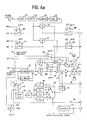
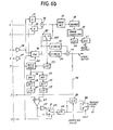
- Fig. 6 is provided which is generally similar to that shown in Fig. 1 except that electronic switches 90 and 91 are provided instead of switches 81 and 82 to selectively couple gating pulses A2, B2, A4 and B4 to gates 26 and 27.
- electronic switches 90 and 91 are provided instead of switches 81 and 82 to selectively couple gating pulses A2, B2, A4 and B4 to gates 26 and 27.
- the operation of the circuit of Fig. 6, will be visualized with reference to a timing diagram shown in Fig. 7.
- switches 86 and 87 are operated as in the previous embodiment.
- switches 90 and 91 are operated to couple gating pulses A4 and B4 to gates 26 and 27.
- the compressed digitized audio signal is applied through gats 26 and 27 to adders 13 and 14 and alternately combined with video signals.
- Switches 83 and 84 are also operated to couple gating pulses All and Bl'. Each of gating pulses All and Bl' lasts for a period less than the total angle of el to e5 by Ta' in which no information is usually recorded.
- Each of the gating pulses A4 and B4 has a duration smaller than the total angle of el and ⁇ 2 by Ta'.
- gating pulses A3' and B3' and sampling pulses each have a duration Ta l .
- the head A During the period Ta the head A remains in the playback mode to detect a pilot signal prerecorded in the no-signal portion of the track area ⁇ 1.
- This pilot signal is applied through amplifier 28, gate 31, adder 36, switch 87 and low-pass filter 53 to the balanced modulator 54 and modulated on the reference pilot signal from the low-pass filter 52.
- the differential amplifier 61 provides a corresponding tracking control signal which is sampled in response to a sampling pulse Sl' and stored in the sample-and-hold 80.
- a gating pulse Al'-l the video head A is switched from playback mode to recording mode.
- the digitized audio signal from gate 26 is recorded over the track area ⁇ 2 of the first track of the insert program.
- the head B When the head A is tracing the trailing portion of this first track, the head B picks up the pilot signal recorded in the no-signal portion of the area ⁇ 1 of the second track, this pilot signal being sampled in response to a sampling pulse S2' and stored until the time of occurrence of the next sampling pulse S3'. The head B is then switched to recording mode in response to a gating pulse Bl l- l to record the audio and video signals on the second track.
- the circuit of Fig. 1 could equally be as well employed.
- the track segments ⁇ 1, ⁇ 2 and ⁇ 3 are combined into a first overlap region 86 having an equal length to that of the segment ⁇ 5.
Landscapes
- Engineering & Computer Science (AREA)
- Signal Processing (AREA)
- Multimedia (AREA)
- Adjustment Of The Magnetic Head Position Track Following On Tapes (AREA)
- Management Or Editing Of Information On Record Carriers (AREA)
Applications Claiming Priority (2)
| Application Number | Priority Date | Filing Date | Title |
|---|---|---|---|
| JP76818/82 | 1982-05-07 | ||
| JP57076818A JPS58194162A (ja) | 1982-05-07 | 1982-05-07 | 回転ヘツド型磁気記録再生装置 |
Publications (3)
| Publication Number | Publication Date |
|---|---|
| EP0094207A2 true EP0094207A2 (fr) | 1983-11-16 |
| EP0094207A3 EP0094207A3 (en) | 1984-12-27 |
| EP0094207B1 EP0094207B1 (fr) | 1988-11-02 |
Family
ID=13616248
Family Applications (1)
| Application Number | Title | Priority Date | Filing Date |
|---|---|---|---|
| EP83302536A Expired EP0094207B1 (fr) | 1982-05-07 | 1983-05-05 | Enregistreur à bande vidéo avec commande continue d'alignement pendant le mode d'édition |
Country Status (4)
| Country | Link |
|---|---|
| US (1) | US4602298A (fr) |
| EP (1) | EP0094207B1 (fr) |
| JP (1) | JPS58194162A (fr) |
| DE (1) | DE3378385D1 (fr) |
Cited By (10)
| Publication number | Priority date | Publication date | Assignee | Title |
|---|---|---|---|---|
| NL8302117A (nl) * | 1982-06-14 | 1984-01-02 | Canon Kk | Inrichting voor het registreren en weergeven van een informatiesignaal. |
| DE3546015A1 (de) * | 1984-12-25 | 1986-06-26 | Mitsubishi Denki K.K., Tokio/Tokyo | Magnetische aufnahme- und wiedergabevorrichtung und -verfahren |
| EP0263546A1 (fr) * | 1986-09-10 | 1988-04-13 | Koninklijke Philips Electronics N.V. | Appareil pour enregistrer des informations dans un support d'enregistrement magnétique |
| EP0213937A3 (en) * | 1985-08-30 | 1988-10-05 | Sony Corporation | Apparatus for recording an information signal |
| EP0508510A3 (en) * | 1991-04-12 | 1993-03-31 | Ampex Corporation | Method and apparatus for automatically optimizing insert editing in a signal recorder |
| EP0508779A3 (fr) * | 1991-04-11 | 1994-02-16 | Matsushita Electric Industrial Co Ltd | |
| EP0368511A3 (fr) * | 1988-11-10 | 1994-02-23 | Ampex Systems Corporation | Synchronisation de transports de milieux d'enregistrement |
| US5416649A (en) * | 1991-04-12 | 1995-05-16 | Ampex Corporation | Single channel method and apparatus for automatically optimizing insert editing in a signal recorder |
| US5420731A (en) * | 1991-04-12 | 1995-05-30 | Ampex Corporation | Two channel method and apparatus for automatically optimizing insert editing in a signal recorder |
| EP0646916A3 (fr) * | 1993-10-05 | 1996-12-27 | Matsushita Electric Industrial Co Ltd | Appareil d'enregistrement magnétique. |
Families Citing this family (12)
| Publication number | Priority date | Publication date | Assignee | Title |
|---|---|---|---|---|
| JPS5975451A (ja) * | 1982-10-21 | 1984-04-28 | Sony Corp | インサ−ト編集装置 |
| EP0138210A3 (fr) * | 1983-10-14 | 1986-02-05 | Hitachi, Ltd. | Appareil d'enregistrement ou de reproduction magnétique du type à tête rotative et méthode pour produire des signaux de commande de suivi de piste |
| JPH0652597B2 (ja) * | 1984-04-06 | 1994-07-06 | 株式会社日立製作所 | 磁気記録再生装置 |
| US5087995A (en) * | 1984-12-06 | 1992-02-11 | Canon Kabushiki Kaisha | Information signal reproducing apparatus for effecting tracking control by using three or more rotary heads |
| US5148331A (en) * | 1985-01-25 | 1992-09-15 | Canon Kabushiki Kaisha | Rotary head type recording and reproducing apparatus for information and additional codes |
| JPS61248257A (ja) * | 1985-04-25 | 1986-11-05 | Canon Inc | 回転ヘツド型記録装置 |
| JP2590821B2 (ja) * | 1986-05-23 | 1997-03-12 | ソニー株式会社 | 磁気記録再生装置 |
| US5084786A (en) * | 1987-09-09 | 1992-01-28 | Hitachi, Ltd. | Magnetic tape memory apparatus with axially displaced heads enabling after recording and verification |
| JP2961939B2 (ja) * | 1991-04-12 | 1999-10-12 | ソニー株式会社 | 編集機能付記録再生装置 |
| JP3312433B2 (ja) * | 1993-08-02 | 2002-08-05 | ソニー株式会社 | ディジタル信号記録再生装置 |
| JP3433609B2 (ja) * | 1996-03-27 | 2003-08-04 | ソニー株式会社 | ディジタルビデオ記録装置および記録方法 |
| JP2008184184A (ja) * | 2007-01-30 | 2008-08-14 | Mitsubishi Electric Corp | 包装体 |
Family Cites Families (15)
| Publication number | Priority date | Publication date | Assignee | Title |
|---|---|---|---|---|
| US3549797A (en) * | 1967-09-05 | 1970-12-22 | Bell & Howell Co | Track alignment system in slant-track video tape recorder |
| US3671665A (en) * | 1967-11-27 | 1972-06-20 | Victor Company Of Japan | Signal editing system and apparatus for recording and reproducing apparatus |
| US3974522A (en) * | 1973-07-26 | 1976-08-10 | Akai Electric Company Limited | Electronic editing method and apparatus for a video tape recorder |
| JPS51138410A (en) * | 1975-05-26 | 1976-11-30 | Sony Corp | Method of recording and reproducing signal |
| JPS6032258B2 (ja) * | 1976-09-13 | 1985-07-26 | ソニー株式会社 | 自動トラツキング制御装置 |
| US4044388A (en) * | 1976-10-05 | 1977-08-23 | Eastman Kodak Company | Interactive servo control system for use with a rotating-head magnetic tape player |
| US4120008A (en) * | 1976-10-05 | 1978-10-10 | Eastman Kodak Company | Overlap track servo for dynamic position correction in a rotary-head tape recorder |
| NL7702815A (nl) * | 1977-03-16 | 1978-09-19 | Philips Nv | Werkwijze voor het regelen van de positie van een schrijf- respektievelijk leeskop en een inrichting voor het uitvoeren van de werkwijze. |
| NL7801318A (nl) * | 1978-02-06 | 1979-08-08 | Philips Nv | Werkwijze voor het regelen van de positie van een schrijf-leeskop en inrichting voor het uitvoeren van de werkwijze. |
| NL7808639A (nl) * | 1978-08-22 | 1980-02-26 | Philips Nv | Werkwijze voor het positioneren van weergeefelementen en een inrichting voor het uitvoeren van de werkwijze. |
| NL7812286A (nl) * | 1978-12-19 | 1980-06-23 | Philips Nv | Werkwijze voor het lezen en/of schrijven van informatie en een inrichting voor het uitvoeren van de werkwijze. |
| JPS581829A (ja) * | 1981-05-06 | 1983-01-07 | Sony Corp | ビデオテ−プレコ−ダ |
| JPS58222402A (ja) * | 1982-02-02 | 1983-12-24 | Sony Corp | 情報信号の記録装置 |
| JPS58150162A (ja) * | 1982-03-03 | 1983-09-06 | Hitachi Ltd | 磁気記録再生装置 |
| JPS58188324A (ja) * | 1982-04-28 | 1983-11-02 | Hitachi Ltd | ビデオテ−プレコ−ダ |
-
1982
- 1982-05-07 JP JP57076818A patent/JPS58194162A/ja active Pending
-
1983
- 1983-05-05 DE DE8383302536T patent/DE3378385D1/de not_active Expired
- 1983-05-05 EP EP83302536A patent/EP0094207B1/fr not_active Expired
- 1983-05-06 US US06/492,250 patent/US4602298A/en not_active Expired - Lifetime
Cited By (12)
| Publication number | Priority date | Publication date | Assignee | Title |
|---|---|---|---|---|
| NL8302117A (nl) * | 1982-06-14 | 1984-01-02 | Canon Kk | Inrichting voor het registreren en weergeven van een informatiesignaal. |
| DE3546015A1 (de) * | 1984-12-25 | 1986-06-26 | Mitsubishi Denki K.K., Tokio/Tokyo | Magnetische aufnahme- und wiedergabevorrichtung und -verfahren |
| EP0213937A3 (en) * | 1985-08-30 | 1988-10-05 | Sony Corporation | Apparatus for recording an information signal |
| US4984104A (en) * | 1985-08-30 | 1991-01-08 | Sony Corporation | Apparatus for recording an information signal at a second part of a given track by sampling and holding a tracking control signal used for tracking at a first part of the given track |
| EP0263546A1 (fr) * | 1986-09-10 | 1988-04-13 | Koninklijke Philips Electronics N.V. | Appareil pour enregistrer des informations dans un support d'enregistrement magnétique |
| EP0368511A3 (fr) * | 1988-11-10 | 1994-02-23 | Ampex Systems Corporation | Synchronisation de transports de milieux d'enregistrement |
| EP0508779A3 (fr) * | 1991-04-11 | 1994-02-16 | Matsushita Electric Industrial Co Ltd | |
| EP0508510A3 (en) * | 1991-04-12 | 1993-03-31 | Ampex Corporation | Method and apparatus for automatically optimizing insert editing in a signal recorder |
| US5416649A (en) * | 1991-04-12 | 1995-05-16 | Ampex Corporation | Single channel method and apparatus for automatically optimizing insert editing in a signal recorder |
| US5420731A (en) * | 1991-04-12 | 1995-05-30 | Ampex Corporation | Two channel method and apparatus for automatically optimizing insert editing in a signal recorder |
| US5739973A (en) * | 1993-05-10 | 1998-04-14 | Matsushita Electric Industrial Co., Ltd. | Apparatus for recording a mixed video and tracking signal on a magnetic recording medium |
| EP0646916A3 (fr) * | 1993-10-05 | 1996-12-27 | Matsushita Electric Industrial Co Ltd | Appareil d'enregistrement magnétique. |
Also Published As
| Publication number | Publication date |
|---|---|
| EP0094207B1 (fr) | 1988-11-02 |
| DE3378385D1 (en) | 1988-12-08 |
| JPS58194162A (ja) | 1983-11-12 |
| US4602298A (en) | 1986-07-22 |
| EP0094207A3 (en) | 1984-12-27 |
Similar Documents
| Publication | Publication Date | Title |
|---|---|---|
| EP0094207B1 (fr) | Enregistreur à bande vidéo avec commande continue d'alignement pendant le mode d'édition | |
| JP2684695B2 (ja) | データ記録装置 | |
| US4484236A (en) | Magnetic tape recording and reproducing arrangements | |
| US4899233A (en) | Apparatus for reproducing a magnetically recorded digital signal using a rotary head with automatic track finding signal extraction and selection for tracking control | |
| US4758904A (en) | Apparatus for recording and/or reproducing an additional information signal | |
| EP0630010B1 (fr) | Appareil d'enregistrement de signaux d'informations et appareil de reproduction comprenant chacun des moyens de commande de suivi des pistes | |
| JPS63298863A (ja) | 画像情報再生装置 | |
| JP3237439B2 (ja) | コントロールトラック記録方法 | |
| US6134074A (en) | Reproducing apparatus having tracking control in accordance with track number information | |
| JPS6355274B2 (fr) | ||
| JPH0799627A (ja) | タイムラプス磁気記録再生装置 | |
| JP2593841B2 (ja) | 同期信号検出回路 | |
| KR100772081B1 (ko) | 자기 테이프 트래킹 제어 장치 및 방법, 자기 테이프포맷, 기록 매체 및 프로그램 | |
| JP3433691B2 (ja) | 画像信号記録再生装置 | |
| JPS61168166A (ja) | 回転ヘツド式テ−プレコ−ダの再生制御方法 | |
| JPH06195817A (ja) | 磁気記録再生装置のトラッキング制御方式 | |
| JPH0352169A (ja) | デジタルテープレコーダ | |
| JPS59168962A (ja) | 磁気録画再生装置のテ−プ送り位相の制御方法 | |
| JPH05328274A (ja) | 磁気記録再生装置 | |
| JPH0884313A (ja) | 磁気記録再生装置 | |
| JPH03144966A (ja) | 磁気記録再生装置 | |
| JPH06325549A (ja) | 記録再生方法 | |
| JPS6286501A (ja) | 磁気記録再生装置 | |
| JPS63299475A (ja) | 画像再生装置 | |
| JPS6318785A (ja) | 回転ヘツド型ビデオ信号再生装置 |
Legal Events
| Date | Code | Title | Description |
|---|---|---|---|
| PUAI | Public reference made under article 153(3) epc to a published international application that has entered the european phase |
Free format text: ORIGINAL CODE: 0009012 |
|
| AK | Designated contracting states |
Designated state(s): DE FR GB |
|
| PUAL | Search report despatched |
Free format text: ORIGINAL CODE: 0009013 |
|
| AK | Designated contracting states |
Designated state(s): DE FR GB |
|
| 17P | Request for examination filed |
Effective date: 19850227 |
|
| 17Q | First examination report despatched |
Effective date: 19860919 |
|
| R17C | First examination report despatched (corrected) |
Effective date: 19870330 |
|
| GRAA | (expected) grant |
Free format text: ORIGINAL CODE: 0009210 |
|
| AK | Designated contracting states |
Kind code of ref document: B1 Designated state(s): DE FR GB |
|
| REF | Corresponds to: |
Ref document number: 3378385 Country of ref document: DE Date of ref document: 19881208 |
|
| ET | Fr: translation filed | ||
| PLBE | No opposition filed within time limit |
Free format text: ORIGINAL CODE: 0009261 |
|
| STAA | Information on the status of an ep patent application or granted ep patent |
Free format text: STATUS: NO OPPOSITION FILED WITHIN TIME LIMIT |
|
| 26N | No opposition filed | ||
| PGFP | Annual fee paid to national office [announced via postgrant information from national office to epo] |
Ref country code: DE Payment date: 20010430 Year of fee payment: 19 |
|
| PGFP | Annual fee paid to national office [announced via postgrant information from national office to epo] |
Ref country code: GB Payment date: 20010502 Year of fee payment: 19 |
|
| PGFP | Annual fee paid to national office [announced via postgrant information from national office to epo] |
Ref country code: FR Payment date: 20010518 Year of fee payment: 19 |
|
| REG | Reference to a national code |
Ref country code: GB Ref legal event code: IF02 |
|
| PG25 | Lapsed in a contracting state [announced via postgrant information from national office to epo] |
Ref country code: GB Free format text: LAPSE BECAUSE OF NON-PAYMENT OF DUE FEES Effective date: 20020505 |
|
| PG25 | Lapsed in a contracting state [announced via postgrant information from national office to epo] |
Ref country code: DE Free format text: LAPSE BECAUSE OF NON-PAYMENT OF DUE FEES Effective date: 20021203 |
|
| GBPC | Gb: european patent ceased through non-payment of renewal fee |
Effective date: 20020505 |
|
| PG25 | Lapsed in a contracting state [announced via postgrant information from national office to epo] |
Ref country code: FR Free format text: LAPSE BECAUSE OF NON-PAYMENT OF DUE FEES Effective date: 20030131 |
|
| REG | Reference to a national code |
Ref country code: FR Ref legal event code: ST |