EP0094236A1 - Verfahren zur Übertragung von UV-Licht - Google Patents
Verfahren zur Übertragung von UV-Licht Download PDFInfo
- Publication number
- EP0094236A1 EP0094236A1 EP83302606A EP83302606A EP0094236A1 EP 0094236 A1 EP0094236 A1 EP 0094236A1 EP 83302606 A EP83302606 A EP 83302606A EP 83302606 A EP83302606 A EP 83302606A EP 0094236 A1 EP0094236 A1 EP 0094236A1
- Authority
- EP
- European Patent Office
- Prior art keywords
- light
- nanometers
- fiber
- responsive
- intensity
- Prior art date
- Legal status (The legal status is an assumption and is not a legal conclusion. Google has not performed a legal analysis and makes no representation as to the accuracy of the status listed.)
- Withdrawn
Links
Images
Classifications
-
- C—CHEMISTRY; METALLURGY
- C03—GLASS; MINERAL OR SLAG WOOL
- C03C—CHEMICAL COMPOSITION OF GLASSES, GLAZES OR VITREOUS ENAMELS; SURFACE TREATMENT OF GLASS; SURFACE TREATMENT OF FIBRES OR FILAMENTS MADE FROM GLASS, MINERALS OR SLAGS; JOINING GLASS TO GLASS OR OTHER MATERIALS
- C03C13/00—Fibre or filament compositions
- C03C13/04—Fibre optics, e.g. core and clad fibre compositions
- C03C13/045—Silica-containing oxide glass compositions
-
- G—PHYSICS
- G02—OPTICS
- G02B—OPTICAL ELEMENTS, SYSTEMS OR APPARATUS
- G02B6/00—Light guides; Structural details of arrangements comprising light guides and other optical elements, e.g. couplings
- G02B6/10—Light guides; Structural details of arrangements comprising light guides and other optical elements, e.g. couplings of the optical waveguide type
- G02B6/102—Light guides; Structural details of arrangements comprising light guides and other optical elements, e.g. couplings of the optical waveguide type for infrared and ultraviolet radiation
Definitions
- This invention relates to a method of transmitting light having a substantial ultraviolet (UV) component via an optical fiber.
- UV ultraviolet
- UV light is meant light having a wavelength between about 150 and 400. nanometers, with that portion having a wavelength less than about 200 nanometers being referred to as the vacuum ultraviolet.
- fused silica As fused silica has the lowest UV absorption of glassy materials, it is potentially an extremely suitable core material for a UV transmitting fiber, but its low index of refraction makes the finding of a suitable cladding difficult. It has therefore been a common practice to dope the silica core to raise its refractive index sufficiently to permit undoped silica to be used as the cladding, but most such fibers, having a doped fused silica core and a fused silica cladding, are not satisfactory for UV transmission since the dopants cause the fiber to absorb some components of UV light.
- Organic polymer claddings notably siloxanes (polydimethyl siloxanes) and fluorocarbons such as FEP (fluorinated ethylene-propylene) which have a lower refractive index than fused silica, have been used for silica cored fibers, and such fibers (generically referred to as PCS fibers) will transmit UV light.
- siloxanes polydimethyl siloxanes
- fluorocarbons such as FEP (fluorinated ethylene-propylene) which have a lower refractive index than fused silica
- FEP fluorinated ethylene-propylene
- the invention provides a method of transmitting light of which the ratio of the intensity in the wavelength range from 150 to 300 nanometers to the intensity in the wavelength range from 150 to 400 nanometers is at least 10%, which comprises directing said light onto one part, preferably one end, of an optical fiber and receiving the light transmitted through said fiber on emission thereof from another part, preferably the other end, of said fiber, wherein said fiber comprises a core consisting substantially only of synthetic fused silica and a cladding consisting substantially only of fluorine-doped synthetic fused silica.
- the invention also provides apparatus comprising:
- the dopants present in fluorine-doped fused silica cladding do not cause increased UV absorption and that in consequence the specified optical fibers comprising a core consisting substantially only of synthetic fused silica and a cladding consisting substantially only of fluorine-doped synthetic fused silica are capable of UV transmission to below 200 nanometers.
- Such fibers were previously known for their radiation hardness, that is their ability to resist interference from external radiation while transmitting ordinary wavelengths, and methods for their manufacture are disclosed in, inter alia, U.S. Patents Nos. 4,082,420; 4,161,505; 4,162,908; 4,165,152; 4,165,915; 4,221,825; 4,242,375; and 4,295,869.
- Preforms for such fibers are generally produced by the combustion of a silicon compound in oxygen to produce synthetic fused silica., and the dopant for the cladding is introduced by the addition to the combustion mixture of a source of the dopant, eg. CCI 2 F 2 . Combustion of the dopant sources in the oxygen produces the dopant material, and by fluorine-doped synthetic fused silica is meant a synthetic fused silica into which has been introduced fluorine or a chemical compound thereof.
- light having a substantial UV component will be understood to mean light of which the ratio of the intensity in the wavelength range from 150 to 300 nanometers, preferably 150 to 280 nanometers, to the intensity in the wavelength range from 150 to 400 nanometers, or of which the ratio of the intensity in the wavelength range from 150 to 200 nanometers to the intensity in the wavelength range from 150 to 250 nanometers, is at least 10%, preferably at least 50%, more preferably at least 90%.
- the present invention makes use of the advantageous compatibility between core and cladding in the specified fibers, the materials having physical properties (especially coefficients of expansion) which are closely similar, and forming an intimate bond to minimize light scattering at the core-cladding interface. Since a high concentration of dopant in a he cladding may alter the coefficient of expansion from that of silica, the dopant concentration should be as high as possible consistent with compatibility between the silica core and the fluorine-doped silica cladding and bearing in mind the difficulty of incorporating a high fluorine content. This generally results in a fluorine content of approximately 4 to 5 mole percent in the fluorine-doped silica.
- the cladding material should be light-transmissive, i.e. its UV cutoff (the point at which it is essentially non-transmissive) should be at a sufficiently short wavelength.
- dopants that interact chemically with the host lattice e.g. alkali and alkaline earth metals and metal oxides, tend to broaden the UV absorption tail of the host, thus increasing the refractive index at short wavelengths, thereby making such materials unsuitable for UV transmission.
- the synthetic fused silica core should contain substantially no elements other than silicon and oxygen and the fluorine -doped synthetic fused silica cladding should contain substantially no elements other than silicon, oxygen, and fluorine.
- Step-index preforms having a fused silica core and a fluorine-doped fused silica cladding are commercially available , e.g. from Heraeus-Amersil Inc. under the trade designation Fluosil. These have an O.D. to core ratio of 1.2 or 1.4. It has been found that fibers suitable for the present invention, having a core diameter of from 50 to 400 micrometers, may be drawn from such preforms using conventional fiber-drawing techniques and may be coated with conventional buffer or jacket layers such as RTV silicone or polyimide.
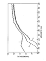
- the accompanying drawing shows the relative transmission of 1 meter lengths of fibers each having a fused silica core and having claddings of (a) siloxane, (b) FEP, and (c) fluorine-doped fused silica. It is apparent from the Figure that the siloxane clad fiber is unusable below about 210 nanometers, and the FEP-clad fiber below about 200 nm, while the fiber clad with fluorine-doped fused silica still has a transmission exceeding 50% at 200 nm.
- the method and apparatus of this invention may be applied to, for example, the detection and quantitation by spectroscopy of materials having spectral lines in the short wavelength UV, "solar-blind" detectors, i.e. detectors for optical sources e.g. sparks or flames, which are insensitive to solar radiation (which has a short wave-length cutoff at about 280 nanometers), and in luminescence thermometers (such as the type described in U.S. Patents No. 4,075,493 and 4,215,275).
- solar-blind detectors i.e. detectors for optical sources e.g. sparks or flames, which are insensitive to solar radiation (which has a short wave-length cutoff at about 280 nanometers)
- luminescence thermometers such as the type described in U.S. Patents No. 4,075,493 and 4,215,275.
- light-responsive means adjacent one end of the fiber which is responsive to light at at least one wavelength less than 300 nanometers, preferably less than 280 nanometers, more preferably less than 250 nanometers, and most preferably less than 200 nanometers.
- the light-responsive means may for example be an optical filter and/or may be capable of determining whether the intensity of light impinging on it at the specified wavelength(s) exceeds a predetermined level, and/or may be capable of determining the quantitative intensity of the impingent light.
- Light-responsive means responsive substantially only to light of less than the specified wavelength(s) may be preferable for some end uses.
- Ultraviolet light sources which may be useful in connection with this invention include electric arcs, sparks, plasmas, and lasers.
- the invention can usefully be applied to indicating the occurrence of an event producing light at the relevant wavelength(s) by positioning the specified optical fiber so that at least some of the light produced will impinge on it, with the aforementioned light-responsive means at the other end of the fiber either constituting, or being connected to, indicator means which is actuated by the transmitted light to provide an indicator signal.
- Such indication can be adapted to spectroscopic analysis by providing means for exciting a sample to cause light at the relevant wavelength(s) to impinge on the optical fibre and thus be transmitted to light responsive means for analysing the transmitted light, or indicating the presence of a predetermined wave- length therein.
- a layer of luminescent material is provided at one end of said optical fiber in optical communication therewith, said luminescent material being characterized by having a substantial response to excitation by light having a wavelength less than 300 nanometers, and by emitting, when excited, light that varies as a function of the temperature of the luminescent material; and means is provided at the other end of said optical fiber for transmitting light, of which the ratio of the intensity in the wavelength range of 150 to 300 nanometers to the intensity in the wavelength range of 150 to 400 nanometers is at least 10%, through said fiber and onto said luminescent material to cause it to emit light; and further means is provided near said other end of said optical fiber for responding to light emitted by said luminescent material to produce signal indicative of the temperature of the luminescent material.
Landscapes
- Physics & Mathematics (AREA)
- Optics & Photonics (AREA)
- Chemical & Material Sciences (AREA)
- General Physics & Mathematics (AREA)
- Health & Medical Sciences (AREA)
- Life Sciences & Earth Sciences (AREA)
- Toxicology (AREA)
- Engineering & Computer Science (AREA)
- Chemical Kinetics & Catalysis (AREA)
- General Chemical & Material Sciences (AREA)
- Geochemistry & Mineralogy (AREA)
- Materials Engineering (AREA)
- Organic Chemistry (AREA)
- Optical Fibers, Optical Fiber Cores, And Optical Fiber Bundles (AREA)
- Glass Compositions (AREA)
Applications Claiming Priority (2)
| Application Number | Priority Date | Filing Date | Title |
|---|---|---|---|
| US37686382A | 1982-05-10 | 1982-05-10 | |
| US376863 | 2003-02-28 |
Publications (1)
| Publication Number | Publication Date |
|---|---|
| EP0094236A1 true EP0094236A1 (de) | 1983-11-16 |
Family
ID=23486819
Family Applications (1)
| Application Number | Title | Priority Date | Filing Date |
|---|---|---|---|
| EP83302606A Withdrawn EP0094236A1 (de) | 1982-05-10 | 1983-05-09 | Verfahren zur Übertragung von UV-Licht |
Country Status (6)
| Country | Link |
|---|---|
| EP (1) | EP0094236A1 (de) |
| JP (1) | JPS58208150A (de) |
| AU (1) | AU1443683A (de) |
| GB (1) | GB2119958A (de) |
| IL (1) | IL68631A0 (de) |
| ZA (1) | ZA833327B (de) |
Cited By (2)
| Publication number | Priority date | Publication date | Assignee | Title |
|---|---|---|---|---|
| EP0326847A3 (de) * | 1988-02-05 | 1990-10-24 | Heraeus Quarzglas GmbH | Übertragungsstrecke für optische Strahlung und deren Anwendungen |
| EP0557587A1 (de) * | 1992-02-28 | 1993-09-01 | Heraeus Quarzglas GmbH | Bauteil für die Übertragung von energiereichem Licht und Verwendung des Bauteils |
Citations (3)
| Publication number | Priority date | Publication date | Assignee | Title |
|---|---|---|---|---|
| US3966300A (en) * | 1972-01-24 | 1976-06-29 | Jenaer Glaswerk Schott & Gen. | Light conducting fibers of quartz glass |
| US4165915A (en) * | 1975-08-16 | 1979-08-28 | Heraeus Quarzschmelze Gmbh | Light conducting fiber |
| US4215275A (en) * | 1977-12-07 | 1980-07-29 | Luxtron Corporation | Optical temperature measurement technique utilizing phosphors |
Family Cites Families (2)
| Publication number | Priority date | Publication date | Assignee | Title |
|---|---|---|---|---|
| US4242375A (en) * | 1972-11-25 | 1980-12-30 | Sumitomo Electric Industries, Ltd. | Process for producing optical transmission fiber |
| GB1456371A (en) * | 1972-11-25 | 1976-11-24 | Sumitomo Electric Industries | Optical transmission fibre |
-
1983
- 1983-05-09 EP EP83302606A patent/EP0094236A1/de not_active Withdrawn
- 1983-05-09 GB GB08312682A patent/GB2119958A/en not_active Withdrawn
- 1983-05-09 IL IL68631A patent/IL68631A0/xx unknown
- 1983-05-10 JP JP58082457A patent/JPS58208150A/ja active Pending
- 1983-05-10 ZA ZA833327A patent/ZA833327B/xx unknown
- 1983-05-10 AU AU14436/83A patent/AU1443683A/en not_active Abandoned
Patent Citations (3)
| Publication number | Priority date | Publication date | Assignee | Title |
|---|---|---|---|---|
| US3966300A (en) * | 1972-01-24 | 1976-06-29 | Jenaer Glaswerk Schott & Gen. | Light conducting fibers of quartz glass |
| US4165915A (en) * | 1975-08-16 | 1979-08-28 | Heraeus Quarzschmelze Gmbh | Light conducting fiber |
| US4215275A (en) * | 1977-12-07 | 1980-07-29 | Luxtron Corporation | Optical temperature measurement technique utilizing phosphors |
Non-Patent Citations (1)
| Title |
|---|
| F. GRUM et al.: "Optical radiation measurements", vol. 1, Radiometry, 1979, pages 138-143, Academic Press, New York, USA * |
Cited By (3)
| Publication number | Priority date | Publication date | Assignee | Title |
|---|---|---|---|---|
| EP0326847A3 (de) * | 1988-02-05 | 1990-10-24 | Heraeus Quarzglas GmbH | Übertragungsstrecke für optische Strahlung und deren Anwendungen |
| EP0557587A1 (de) * | 1992-02-28 | 1993-09-01 | Heraeus Quarzglas GmbH | Bauteil für die Übertragung von energiereichem Licht und Verwendung des Bauteils |
| US5315685A (en) * | 1992-02-28 | 1994-05-24 | Heraeus Quarzglas Gmbh | Component for the transmission of high-energy light, and the application of the component |
Also Published As
| Publication number | Publication date |
|---|---|
| AU1443683A (en) | 1983-11-17 |
| GB2119958A (en) | 1983-11-23 |
| IL68631A0 (en) | 1983-09-30 |
| ZA833327B (en) | 1984-06-27 |
| JPS58208150A (ja) | 1983-12-03 |
| GB8312682D0 (en) | 1983-06-15 |
Similar Documents
| Publication | Publication Date | Title |
|---|---|---|
| US4504114A (en) | Method of transmitting UV light through optical fibers | |
| US6853798B1 (en) | Downhole geothermal well sensors comprising a hydrogen-resistant optical fiber | |
| US8542967B2 (en) | Depressed graded index multi-mode optical fiber | |
| US4834496A (en) | Optical fiber sensors for chemical detection | |
| EP0233310A2 (de) | Wellenleiter-Kommunikations- und Sensorsysteme | |
| RU2463266C2 (ru) | Оптическое волокно с легированной оловом переходной частью между сердцевиной и оболочкой | |
| US11993535B2 (en) | Fiber optic temperature measurement with quantum dot nanocomposite | |
| Uesugi et al. | Optical loss increase of phosphor‐doped silica fiber at high temperature in the long wavelength region | |
| EP0540042B1 (de) | Glasfaser für hohe Eingangsleistung und Herstellungsverfahren dafür | |
| EP0029653A1 (de) | Optische Systeme zum Erfassen und Messen physikalischer Grössen | |
| CN117177948A (zh) | 由于减少的吸收贡献而具有减少的衰减的光纤 | |
| Dianov et al. | Origin of excess loss in single-mode optical fibers with high GeO2-doped silica core | |
| US7813611B2 (en) | Aluminum doped optical fiber | |
| EP0094236A1 (de) | Verfahren zur Übertragung von UV-Licht | |
| WO2009034413A1 (en) | Optical fiber and method for manufacturing | |
| JP2005525699A (ja) | 光増幅器用光ファイバー及びその製造方法 | |
| US8724951B2 (en) | Optical fiber | |
| CA2687970C (en) | Hydrogen-resistant optical fiber/grating structure suitable for use in downhole sensor applications | |
| US20010055445A1 (en) | Very-high-temperature-stable fiber grating-based sensor | |
| Ohmori et al. | Fabrication of low-loss Al2O3-doped silica fibres | |
| Atkins et al. | Profiling of drawing induced defects in optical fibre preforms | |
| Kaiser | NA-dependent spectral loss measurements of optical fibers | |
| Grattan et al. | Luminescent optical fibers in sensing | |
| Weiss | Downhole geothermal well sensors comprising a hydrogen-resistant optical fiber | |
| JP2026044166A (ja) | 発光装置、測定装置、発光方法、及び測定方法 |
Legal Events
| Date | Code | Title | Description |
|---|---|---|---|
| PUAI | Public reference made under article 153(3) epc to a published international application that has entered the european phase |
Free format text: ORIGINAL CODE: 0009012 |
|
| 17P | Request for examination filed |
Effective date: 19830531 |
|
| AK | Designated contracting states |
Designated state(s): AT BE CH DE FR IT LI NL SE |
|
| STAA | Information on the status of an ep patent application or granted ep patent |
Free format text: STATUS: THE APPLICATION IS DEEMED TO BE WITHDRAWN |
|
| 18D | Application deemed to be withdrawn |
Effective date: 19850711 |
|
| RIN1 | Information on inventor provided before grant (corrected) |
Inventor name: ARRINGTON, JOHN PRESTON |