EP0094320B1 - Farbwerk und -verfahren für Druckmaschinen - Google Patents
Farbwerk und -verfahren für Druckmaschinen Download PDFInfo
- Publication number
- EP0094320B1 EP0094320B1 EP83400946A EP83400946A EP0094320B1 EP 0094320 B1 EP0094320 B1 EP 0094320B1 EP 83400946 A EP83400946 A EP 83400946A EP 83400946 A EP83400946 A EP 83400946A EP 0094320 B1 EP0094320 B1 EP 0094320B1
- Authority
- EP
- European Patent Office
- Prior art keywords
- cylinder
- ink
- contact
- forme
- feeder
- Prior art date
- Legal status (The legal status is an assumption and is not a legal conclusion. Google has not performed a legal analysis and makes no representation as to the accuracy of the status listed.)
- Expired
Links
- 238000007639 printing Methods 0.000 title claims description 25
- 238000000034 method Methods 0.000 title abstract description 9
- 239000007788 liquid Substances 0.000 claims abstract description 5
- 239000010409 thin film Substances 0.000 claims abstract description 5
- 239000012263 liquid product Substances 0.000 claims abstract 2
- 239000010408 film Substances 0.000 claims description 15
- 239000000463 material Substances 0.000 claims description 5
- 238000000151 deposition Methods 0.000 claims description 3
- 238000007373 indentation Methods 0.000 claims description 3
- 238000007790 scraping Methods 0.000 claims description 3
- 238000011144 upstream manufacturing Methods 0.000 claims description 3
- 241001466460 Alveolata Species 0.000 claims description 2
- 238000005520 cutting process Methods 0.000 claims description 2
- 230000000694 effects Effects 0.000 claims description 2
- 238000012546 transfer Methods 0.000 claims description 2
- 230000005540 biological transmission Effects 0.000 claims 1
- 238000012986 modification Methods 0.000 claims 1
- 230000004048 modification Effects 0.000 claims 1
- 238000007645 offset printing Methods 0.000 claims 1
- 230000000717 retained effect Effects 0.000 claims 1
- 239000007787 solid Substances 0.000 claims 1
- 239000000976 ink Substances 0.000 description 69
- 238000010586 diagram Methods 0.000 description 7
- 230000035515 penetration Effects 0.000 description 7
- 230000002093 peripheral effect Effects 0.000 description 5
- 230000008569 process Effects 0.000 description 4
- 239000011248 coating agent Substances 0.000 description 3
- 238000000576 coating method Methods 0.000 description 3
- 230000007423 decrease Effects 0.000 description 3
- 230000003071 parasitic effect Effects 0.000 description 3
- 230000009467 reduction Effects 0.000 description 3
- 238000005096 rolling process Methods 0.000 description 3
- 229910000831 Steel Inorganic materials 0.000 description 2
- 230000015556 catabolic process Effects 0.000 description 2
- 238000006731 degradation reaction Methods 0.000 description 2
- 238000003475 lamination Methods 0.000 description 2
- 238000010008 shearing Methods 0.000 description 2
- 238000003892 spreading Methods 0.000 description 2
- 230000007480 spreading Effects 0.000 description 2
- 239000010959 steel Substances 0.000 description 2
- 235000009854 Cucurbita moschata Nutrition 0.000 description 1
- 240000001980 Cucurbita pepo Species 0.000 description 1
- 235000009852 Cucurbita pepo Nutrition 0.000 description 1
- 238000009825 accumulation Methods 0.000 description 1
- 230000009471 action Effects 0.000 description 1
- 230000006978 adaptation Effects 0.000 description 1
- 238000005054 agglomeration Methods 0.000 description 1
- 230000002776 aggregation Effects 0.000 description 1
- 230000015572 biosynthetic process Effects 0.000 description 1
- 239000003086 colorant Substances 0.000 description 1
- 230000002860 competitive effect Effects 0.000 description 1
- 230000007547 defect Effects 0.000 description 1
- 238000001739 density measurement Methods 0.000 description 1
- 238000013461 design Methods 0.000 description 1
- 238000009826 distribution Methods 0.000 description 1
- 239000000428 dust Substances 0.000 description 1
- 239000003292 glue Substances 0.000 description 1
- 239000012535 impurity Substances 0.000 description 1
- 238000010030 laminating Methods 0.000 description 1
- 238000012423 maintenance Methods 0.000 description 1
- 230000003287 optical effect Effects 0.000 description 1
- 239000003973 paint Substances 0.000 description 1
- 239000010893 paper waste Substances 0.000 description 1
- 239000000049 pigment Substances 0.000 description 1
- 239000004033 plastic Substances 0.000 description 1
- 235000020354 squash Nutrition 0.000 description 1
- 238000013519 translation Methods 0.000 description 1
- 238000009736 wetting Methods 0.000 description 1
Images


Classifications
-
- B—PERFORMING OPERATIONS; TRANSPORTING
- B41—PRINTING; LINING MACHINES; TYPEWRITERS; STAMPS
- B41F—PRINTING MACHINES OR PRESSES
- B41F31/00—Inking arrangements or devices
- B41F31/02—Ducts, containers, supply or metering devices
- B41F31/04—Ducts, containers, supply or metering devices with duct-blades or like metering devices
-
- B—PERFORMING OPERATIONS; TRANSPORTING
- B41—PRINTING; LINING MACHINES; TYPEWRITERS; STAMPS
- B41F—PRINTING MACHINES OR PRESSES
- B41F31/00—Inking arrangements or devices
-
- B—PERFORMING OPERATIONS; TRANSPORTING
- B41—PRINTING; LINING MACHINES; TYPEWRITERS; STAMPS
- B41F—PRINTING MACHINES OR PRESSES
- B41F31/00—Inking arrangements or devices
- B41F31/30—Arrangements for tripping, lifting, adjusting, or removing inking rollers; Supports, bearings, or forks therefor
Definitions
- the invention relates to the inking of printing machines with fatty ink.
- An inking device which comprises a touching cylinder capable of being in contact with the printing form, a feeding cylinder having a rigid non-alveolate surface, means for bringing a substantial mass of ink into contact with the surface of the feed cylinder and without contact with the touch cylinder and means for rotating the feed cylinder with a tangential speed lower than that of the touch cylinder (publication EP-A 017 844).
- This device also includes means for adjusting the thickness of the ink layer on the touching cylinder, but these means require numerous adjustments which do not take account of a variable which is the ink redeposited on this cylinder by the form d and which therefore varies according to the form of printing.
- the main problem posed by the inking of an offset or typography press consists in regularly depositing, from a substantial mass of fatty ink, a layer of a few microns thick uniformly distributed over the printing parts of a printing cylinder. The ink thus deposited on this cylinder is then transferred to the paper, either directly in the case of typography, or indirectly, via a cylinder covered with a rubberized sheet called a blanket in the case of offset. .
- the quantity of ink released at the right of each screw must correspond to the ink consumption taken by each transverse zone of the paper. For example, if the print has several strips printed in the longitudinal direction and separated transversely by spaces which must remain blank, the inkwell adjustment screws must be tightened in line with the white areas and more or less open in line with the areas printed, according to the color intensity of these bands.
- a device in order to apply a thin film of a high viscosity ink on a rotary printing form, a device is used. as defined in the characterizing part of claim 1.
- the wiper cylinder E is kept under pressure on the toucher T coated with a flexible material. These two cylinders rotate in the same direction of rotation so that the ink film included in the contact area m is driven in one direction by the cylinder E and in the other direction by the toucher T. This film is therefore somehow sheared in its thickness.
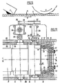
- fig. 3 shows the variant corresponding to the first certificate of addition of the aforementioned patent.
- the laminating cylinder L has been removed and the wiping cylinder E remains, but to avoid the return of the ink coming from the reserve on the sheared layer, two rakes R1 and R2 have been arranged which clean the surface of the wiping cylinder E before that it does not come into contact with the layer spread on the touchpad T.
- FIG. 4a The device described in the last aforementioned patent is shown in FIG. 4a.
- the wiper cylinder E has been reduced in diameter to increase the pressure on the ink film and reduce its thickness.
- This cylinder has thus become a rod, still referenced E, which is kept in pressure over its entire length against the toucher T by a V-groove formed in a cross-member Tr.
- the rakes R1 and R2 of the preceding device are replaced by the tangents x and y at the contact points of the rod E and its support Tr as shown in the diagram developed in FIG. 4b.
- These contact lines are supposed to prevent the ink from passing and coming to superimpose the layer. sheared thickness e.
- the thickness of the ink layer e is a few microns. A variation of 10% in this thickness results in a variation visible to the eye in the optical density of the printed product. It can therefore be seen that the links x and y must be perfectly sealed or allow only a tiny film of ink of constant thickness to pass, a film which is superimposed on the film e of the sheared ink.
- the rod E does not rotate any more and can be replaced by a cylindrical surface of radius r maintained in pressure on the toucher T.
- the thickness of sheared ink e then only depends on two factors, namely the radius r and penetration, apart from the usual factors such as ink viscosity, hardness of the flexible coating and speed V. When the speed increases, the penetration must therefore be increased. The limit is determined by the degradation of the touchpad surface.
- the invention like the state of the art, uses a flexible surface touch cylinder coated with a thin film of ink and depositing it on the printing form, this thin layer being determined in contact between this touch and a rigid cylinder at different peripheral speed.
- the ink is supplied at the point of contact while being carried by the surface of the touching cylinder, and partly withdrawn by the rigid cylinder, called for this reason wiping cylinder, in the invention on the contrary, the ink is supplied in the form of a calibrated film carried by the surface of the rigid cylinder, called for this reason the feed cylinder, and is spread at the point of contact with the touch cylinder.
- the reserve g of fatty ink is not in contact with the touching cylinder T but on the contrary with a supplying cylinder A, as it appears in particular in FIGS. 6, 7, 8 and 10.
- This mass g is between this feed cylinder A, a knife 1 and two cheeks 2 provided with indentations in an arc of a circle for bearing by interlocking transversely on the cylindrical surface of the feed cylinder A , which is naturally a rigid cylinder, preferably metallic.
- the knife i is secured to the cheeks 2 by means of micrometric screws 3 making it possible to adjust the distance d, visible in particular in FIG. 9, between the generator of cylinder A and the edge of knife 1 very precisely.
- the knife 1 is made integral, transversely with respect to the axis of the feed cylinder A, and by means of the screws 3 and a cross member 4, of the two cheeks 2 which bear on the cylinder A. in this way the distance d is independent of the inevitable runout of this cylinder.
- the knife 1 is sharpened in the manner of a cutting tool, as shown in FIG. 9, with however a small rectified dish of width a close to a tenth of a millimeter so that the edge thus obtained is perfectly straight.
- the knife 1 cuts a slice of ink of thickness d, independent of the speed of the cylinder or of the characteristics of the ink.
- the knife edge never being in contact with the cylinder, no wear can result.
- the thickness d can vary from 10 to 60 microns depending on the precision of the micrometric screws.
- the cylinder A is movable and kept under pressure on the touch switch T, coated in the usual manner with a layer 5 of flexible material.
- the differential speed of the surfaces in contact at point 7 is obtained in this example by a rotation in the same direction of these two cylinders as represented by the arrows in FIG. 6.
- a doctor blade 6 eliminates from the periphery of the toucher T the ink not used by the printer form F and deposits it on the feed cylinder A which brings it back into the reserve g.
- this licking can cause small clumps of ink at the periphery of the toucher, which can be reduced in a known manner by placing a cylinder 8 rolling at the periphery of the touching cylinder.
- this cylinder 8 may prove to be insufficient to eliminate these clumps and obtain a perfectly uniform layer.
- an equalizing cylinder 9 which is driven in the opposite direction of the touching cylinder at a peripheral speed V ′ close to the peripheral speed V of the toucher, either positively by gears or by simple contact. with the toucher.
- this cylinder g is in contact with the feeder A. Its action does not in any way modify the balance of ink thicknesses defined by the above formula. As seen in fig.
- the ink layer of thickness d arriving at the contact zone 10 between the equalizing cylinder 9 and the feed cylinder A is divided in two, one of which follows the curved path on the equalizing cylinder 9 to reach the zone 11 between the equalizing cylinder 9 and the toucher T, and the other follows the curved path, on the cylinder A, going from the zone 10 to the zone T, then another curved path on the touching cylinder T going from the zone 7 to zone 11. Due to the speed differences between V ′ and v there is shearing of the ink layer d in the zone 10, then lamination in the zone 11. Thus, the entire thickness has undergone an extremely effective lamination in 10, 7 and 11, thus avoiding any ink agglomeration at the periphery of the toucher.
- this equalizing cylinder 9 can in a known manner be driven in an axial reciprocating movement to improve the regularity of the ink film and avoid the formation of possible streaks.
- the equalizing cylinder 9 no longer rotates at the speed V 'close to V but at a speed close to y.
- the spreading phenomenon which previously occurred in zone 7 (or 10) would occur in zone 11, and therefore it would no longer be necessary to have contact between the cylinders A and T in the zone 7.
- the ink layer of calibrated thickness d fed at slow speed by the feed cylinder A can be spread over the touch cylinder T at a higher peripheral speed, ie directly in the case examined first , either indirectly in the case of the variant that we have just seen, without this going beyond the ambit of the invention.
- the method according to the invention it can be seen that one is thus in control of the value of the thickness e qut becomes independent of the speed of the machine, insofar as the ratio v / V remains constant, and independent of the viscosity of the ink and its temperature, contrary to the state of the art.
- the apparatus is moreover insensitive to wear, due on the one hand to the absence of contact between the knife 1 and the feed cylinder A, and on the other hand to the low speed of rotation of the cylinder A relative to to the T-touch.
- a relatively simple material makes it possible to obtain both high inking precision and high working speed compatible with industrial exploitation.
- the two cheeks 2 are independent and provided on their opposite faces with a groove 12 which does not open outwards and in which each of the ends of the cross member 4 is mounted and supported. 3 for micrometric adjustment of the knife 1, preferably with differential pitch.
- This knife 1 is itself guided in parallel in these grooves 12 and mounted by means of balls 13 to allow a slight angular adaptation of each of the cheeks 2 relative to the knife 1.
- Each of the cheeks 2 rests on the cylinder A by a thicker part in which is cut the cylindrical notch exposed above, and this thick part ends in an oblique shoulder 14 on which comes into contact a pusher 15 actuated by a spring 16 and itself sliding obliquely in a flange 17 carrying the journal bearing 18 of the cylinder A, a similar arrangement being provided at the other end of the cylinder.
- the oblique thrust produced by the pushers 15 on the cheeks 2 produces both their tight application on the periphery of the cylinder A, and their mutual approximation until contact with the balls 13, the seal between the ends of the knife 1 and the cheeks being ensured by the nesting in the grooves 12 and by the functional force of application in the drive direction.
- the two flanges 17 are integral with a cradle 19 oscillating about an axis 19a fixed in the frame 20.
- the penetration of the cylinder A into the touchor T is ensured by a pushing device 21, constituted by a spring or by preferably by a double-acting cylinder allowing the pressurization and depressurization, and limited in amplitude by a stop screw 22.
- the touching cylinder T rotating in the frame 20 in contact with the printing form F, is driven in the opposite direction and at the same tangential speed as the printing form P by means of gears 32 and 33.
- From its shaft end 23 is preferably connected to a speed variator 24 making it possible to adjust the v / V ratio at will, and from this latter comes a pulley 25 driving by a belt 26-a larger pulley 27 already providing a stage reduction in the desired direction.
- This pulley 27 drives a shaft 28 swiveling in a fixed bearing 29, which shaft is connected to the shaft end 30 of the feed cylinder A by means of an oldham constant velocity joint or the like tolerating the movements of the cradle 19.
- the invention could also be used to apply any thin film of a viscous liquid, such as paint, glue, or the like, to any surface which is scrolled by rotation or translation.
- a viscous liquid such as paint, glue, or the like
Landscapes
- Inking, Control Or Cleaning Of Printing Machines (AREA)
- Dot-Matrix Printers And Others (AREA)
- Impression-Transfer Materials And Handling Thereof (AREA)
Claims (9)
Priority Applications (1)
| Application Number | Priority Date | Filing Date | Title |
|---|---|---|---|
| AT83400946T ATE31899T1 (de) | 1982-05-10 | 1983-05-10 | Farbwerk und -verfahren fuer druckmaschinen. |
Applications Claiming Priority (2)
| Application Number | Priority Date | Filing Date | Title |
|---|---|---|---|
| FR8208107A FR2526370B1 (fr) | 1982-05-10 | 1982-05-10 | Procede et dispositif d'encrage pour machine d'imprimerie |
| FR8208107 | 1982-05-10 |
Publications (2)
| Publication Number | Publication Date |
|---|---|
| EP0094320A1 EP0094320A1 (de) | 1983-11-16 |
| EP0094320B1 true EP0094320B1 (de) | 1988-01-13 |
Family
ID=9273875
Family Applications (1)
| Application Number | Title | Priority Date | Filing Date |
|---|---|---|---|
| EP83400946A Expired EP0094320B1 (de) | 1982-05-10 | 1983-05-10 | Farbwerk und -verfahren für Druckmaschinen |
Country Status (7)
| Country | Link |
|---|---|
| US (1) | US4542693A (de) |
| EP (1) | EP0094320B1 (de) |
| JP (1) | JPS59500808A (de) |
| AT (1) | ATE31899T1 (de) |
| DE (1) | DE3375289D1 (de) |
| FR (1) | FR2526370B1 (de) |
| WO (1) | WO1983004003A1 (de) |
Families Citing this family (17)
| Publication number | Priority date | Publication date | Assignee | Title |
|---|---|---|---|---|
| DE3300303C2 (de) * | 1983-01-07 | 1985-03-14 | Deutsche Thomson-Brandt Gmbh, 7730 Villingen-Schwenningen | Kopftrommel mit um eine Achse rotierenden Video-Aufzeichnungs- und Wiedergabeköpfen |
| FR2590205A1 (fr) * | 1985-11-21 | 1987-05-22 | Seailles Tison Sa | Dispositif pour l'encrage d'une forme d'impression rotative a partir d'une masse compacte d'encre a viscosite elevee |
| JPS6440369A (en) * | 1987-08-06 | 1989-02-10 | Kyokuto Int | Printing method and device |
| CH680660A5 (de) * | 1989-12-12 | 1992-10-15 | Fankhauser Peter | |
| US5078063A (en) * | 1990-12-19 | 1992-01-07 | Ag Communication Systems Corporation | Precision mechanical squeegee holding assembly |
| DE4239793A1 (de) * | 1992-01-03 | 1993-07-08 | Noelle Gmbh | |
| JPH05229101A (ja) * | 1992-02-20 | 1993-09-07 | Manabu Fukuda | インキ装置 |
| GB2278574A (en) * | 1993-06-01 | 1994-12-07 | David Edward Mcmanamon | Ink transfer means for printing machine |
| WO1996002390A1 (de) * | 1994-07-14 | 1996-02-01 | Koenig & Bauer-Albert Aktiengesellschaft | Druckwerk mit kurzfarbwerk einer rotationsdruckmaschine für direktdruck mittels einer 'wasserlosen' flachdruckplatte |
| DE19535266A1 (de) * | 1995-09-22 | 1997-04-03 | Roland Man Druckmasch | Kurzfarbwerk |
| US6672211B2 (en) * | 1999-03-03 | 2004-01-06 | James F. Price | Inking systems for printing presses |
| ATE295781T1 (de) | 1999-03-03 | 2005-06-15 | James F Price | Schraubenloses farbwerk für eine druckmaschine |
| US6895861B2 (en) | 2003-07-11 | 2005-05-24 | James F. Price | Keyless inking systems and methods using subtractive and clean-up rollers |
| KR100649722B1 (ko) * | 2000-04-21 | 2006-11-24 | 엘지.필립스 엘시디 주식회사 | 일렉트로루미네센스 표시소자의 패터닝장치 및 이를이용한 패터닝방법 |
| JP2001346031A (ja) * | 2000-06-05 | 2001-12-14 | Fuji Photo Film Co Ltd | 画像合成方法及び装置 |
| JP2003154630A (ja) * | 2001-08-06 | 2003-05-27 | Fuji Photo Film Co Ltd | インキ供給装置及び印刷機 |
| EP1764216A1 (de) * | 2005-09-16 | 2007-03-21 | Kba-Giori S.A. | Vorrichtung zur Beschichtung eines Zylinders, insbesondere eines Wischzylinders einer Tiefdruckmaschine |
Family Cites Families (17)
| Publication number | Priority date | Publication date | Assignee | Title |
|---|---|---|---|---|
| DE639293C (de) * | 1936-12-02 | Richard Lehmann | Farbwerk fuer Druckmaschinen | |
| GB544480A (en) * | 1940-08-07 | 1942-04-15 | American Bank Note Co | Inking mechanisms for rotary steel plate printing machines |
| DE1162852B (de) * | 1955-12-29 | 1964-02-13 | Harris Intertype Corp | Farbkasten fuer Druckmaschinen |
| GB871786A (en) * | 1957-01-18 | 1961-06-28 | Maschf Augsburg Nuernberg Ag | Damping apparatus for rotary printing presses |
| US3026795A (en) * | 1957-01-18 | 1962-03-27 | Maschf Augsburg Nuernberg Ag | Dampening apparatus for rotary printing presses |
| FR1344700A (fr) * | 1963-01-16 | 1963-11-29 | Philips Nv | Procédé et dispositif pour l'examen de corps semi-conducteurs |
| GB1203848A (en) * | 1967-09-18 | 1970-09-03 | Albert Schnellpressen | Improvements in or relating to ink duct assemblies for printing presses |
| US3585932A (en) * | 1968-06-07 | 1971-06-22 | Wallace H Granger | Automatic inking system for rotary newspaper printing press |
| GB1267947A (en) * | 1969-10-30 | 1972-03-22 | Metal Box Co Ltd | Improvements in inking apparatus for printing machines |
| US3709147A (en) * | 1970-12-03 | 1973-01-09 | W Granger | Ink transfer cylinder mounting with adjustable drive clutch |
| US4041864A (en) * | 1972-05-09 | 1977-08-16 | Dahlgren Manufacturing Company | Method and apparatus for inking printing plates |
| CH573812A5 (de) * | 1973-08-28 | 1976-03-31 | Texogesa Sa | |
| US4127067A (en) * | 1974-02-15 | 1978-11-28 | Dahlgren Harold P | Method for inking printing plates |
| US3978788A (en) * | 1975-05-16 | 1976-09-07 | Roland Offsetmaschinenfabrik Faber & Schleicher Ag | Ink metering assembly for printing press |
| US4058058A (en) * | 1976-02-26 | 1977-11-15 | George Hantscho Company, Inc. | Ink fountain for printing presses |
| GB1525805A (en) * | 1976-05-14 | 1978-09-20 | Rotobind Ltd | Printing apparatus and method |
| DE2916291A1 (de) * | 1979-04-21 | 1980-10-30 | Maschf Augsburg Nuernberg Ag | Farbwerk fuer eine druckmaschine |
-
1982
- 1982-05-10 FR FR8208107A patent/FR2526370B1/fr not_active Expired
-
1983
- 1983-05-10 EP EP83400946A patent/EP0094320B1/de not_active Expired
- 1983-05-10 JP JP58501560A patent/JPS59500808A/ja active Pending
- 1983-05-10 AT AT83400946T patent/ATE31899T1/de not_active IP Right Cessation
- 1983-05-10 US US06/572,748 patent/US4542693A/en not_active Expired - Fee Related
- 1983-05-10 DE DE8383400946T patent/DE3375289D1/de not_active Expired
- 1983-05-10 WO PCT/FR1983/000090 patent/WO1983004003A1/fr not_active Ceased
Also Published As
| Publication number | Publication date |
|---|---|
| US4542693A (en) | 1985-09-24 |
| WO1983004003A1 (fr) | 1983-11-24 |
| DE3375289D1 (en) | 1988-02-18 |
| EP0094320A1 (de) | 1983-11-16 |
| FR2526370B1 (fr) | 1986-01-17 |
| ATE31899T1 (de) | 1988-01-15 |
| JPS59500808A (ja) | 1984-05-10 |
| FR2526370A1 (fr) | 1983-11-10 |
Similar Documents
| Publication | Publication Date | Title |
|---|---|---|
| EP0094320B1 (de) | Farbwerk und -verfahren für Druckmaschinen | |
| FR2550994A1 (fr) | Dispositif de mouillage d'un cylindre porte-cliche et procede d'impression sans defaut | |
| FR2628681A1 (fr) | Tambour guide-feuille pour rotatives a feuilles | |
| FR2663588A1 (fr) | Systeme de mouillage a film pour presse offset rotative. | |
| EP1453682B1 (de) | Reinigung von stoffstrahlspritzköpfen | |
| EP2457857B1 (de) | Transfervorrichtung für ein Blatt, und entsprechende Anwendung | |
| EP1140376B1 (de) | Verfahren und vorrichtung zum kontinuierlichen beschichten zumindest eines metallischen bandes mit flüssigkeitsfilm aus vernetzbarem polymer | |
| CA2662971A1 (fr) | Dispositif d'impression par transfert sur un support d'impression cylindrique | |
| CA2189539C (fr) | Pochoir pour le depot et le dosage de couches plus ou moins epaisses, a base de points, d'un produit visqueux | |
| FR2898600A1 (fr) | Appareil et procede pour detacher des troncons de barreaux de verre, troncon de barreaux de verre ainsi produit et guide d'onde optique comprenant un tel troncon | |
| FR2763278A1 (fr) | Procede pour regler l'encrage pour l'impression continue dans une presse rotative a imprimer | |
| EP3880455A1 (de) | System zum schneiden von bändern mittels schraubenförmiger messer und entsprechendes schneidverfahren | |
| FR2583313A1 (fr) | Procede et appareil de revetement d'une nappe continue par raclage. | |
| FR2556278A1 (fr) | Dispositif de mouillage d'un cylindre porte-cliche et procede d'impression sans defaut | |
| EP0338907B1 (de) | Druckmaschine mit einem rotierenden Tampon für das Drucken auf dem Rand von Autofenstern | |
| FR2667975A1 (fr) | Appareil de nettoyage de cylindres de calandrage. | |
| FR2598337A1 (fr) | Racleur cuneiforme pour machine d'enduction de materiau en bande | |
| FR2595673A1 (fr) | Perfectionnements aux enrouleuses a compression | |
| JPH11511377A (ja) | 送出ロール付リバースグラビアキスコーティング装置 | |
| EP0038729B1 (de) | Vorrichtung zum Aufbringen einer Beschichtungsschicht auf ein kontinuierlich durchlaufendes Band | |
| FR2513608A1 (fr) | Appareil de manutention de feuilles minces de materiau | |
| FR2816603A1 (fr) | Plieuse avec un dispositif de decoupe a longueur variable | |
| EP0885720A1 (de) | Multifunktionales farbwerk für eine flexodruckmaschine | |
| FR2948061A1 (fr) | Procede de reglage de la vitesse angulaire de cylindres d'impression | |
| EP1336454B1 (de) | Verfahren und Vorrichtung zur Feinstbearbeitung der Lagerfläche eines Werkstücks, insbesondere für die Feinstbearbeitung der Nockenfläche einer Nockenwelle |
Legal Events
| Date | Code | Title | Description |
|---|---|---|---|
| PUAI | Public reference made under article 153(3) epc to a published international application that has entered the european phase |
Free format text: ORIGINAL CODE: 0009012 |
|
| AK | Designated contracting states |
Designated state(s): AT BE CH DE FR GB IT LI LU NL SE |
|
| 17P | Request for examination filed |
Effective date: 19840319 |
|
| GRAA | (expected) grant |
Free format text: ORIGINAL CODE: 0009210 |
|
| AK | Designated contracting states |
Kind code of ref document: B1 Designated state(s): AT BE CH DE FR GB IT LI LU NL SE |
|
| PG25 | Lapsed in a contracting state [announced via postgrant information from national office to epo] |
Ref country code: NL Effective date: 19880113 Ref country code: IT Free format text: LAPSE BECAUSE OF FAILURE TO SUBMIT A TRANSLATION OF THE DESCRIPTION OR TO PAY THE FEE WITHIN THE PRESCRIBED TIME-LIMIT;WARNING: LAPSES OF ITALIAN PATENTS WITH EFFECTIVE DATE BEFORE 2007 MAY HAVE OCCURRED AT ANY TIME BEFORE 2007. THE CORRECT EFFECTIVE DATE MAY BE DIFFERENT FROM THE ONE RECORDED. Effective date: 19880113 Ref country code: AT Effective date: 19880113 |
|
| REF | Corresponds to: |
Ref document number: 31899 Country of ref document: AT Date of ref document: 19880115 Kind code of ref document: T |
|
| REF | Corresponds to: |
Ref document number: 3375289 Country of ref document: DE Date of ref document: 19880218 |
|
| PG25 | Lapsed in a contracting state [announced via postgrant information from national office to epo] |
Ref country code: LU Free format text: LAPSE BECAUSE OF NON-PAYMENT OF DUE FEES Effective date: 19880531 Ref country code: LI Effective date: 19880531 Ref country code: CH Effective date: 19880531 |
|
| R20 | Corrections of a patent specification |
Effective date: 19880406 |
|
| NLV1 | Nl: lapsed or annulled due to failure to fulfill the requirements of art. 29p and 29m of the patents act | ||
| GBV | Gb: ep patent (uk) treated as always having been void in accordance with gb section 77(7)/1977 [no translation filed] | ||
| PLBE | No opposition filed within time limit |
Free format text: ORIGINAL CODE: 0009261 |
|
| STAA | Information on the status of an ep patent application or granted ep patent |
Free format text: STATUS: NO OPPOSITION FILED WITHIN TIME LIMIT |
|
| PG25 | Lapsed in a contracting state [announced via postgrant information from national office to epo] |
Ref country code: GB Free format text: LAPSE BECAUSE OF NON-PAYMENT OF DUE FEES Effective date: 19881122 |
|
| BERE | Be: lapsed |
Owner name: MOURRELLON GEORGES Effective date: 19880531 |
|
| 26N | No opposition filed | ||
| REG | Reference to a national code |
Ref country code: CH Ref legal event code: PL |
|
| PG25 | Lapsed in a contracting state [announced via postgrant information from national office to epo] |
Ref country code: DE Effective date: 19890201 |
|
| PG25 | Lapsed in a contracting state [announced via postgrant information from national office to epo] |
Ref country code: BE Effective date: 19890531 |
|
| PGFP | Annual fee paid to national office [announced via postgrant information from national office to epo] |
Ref country code: FR Payment date: 19890629 Year of fee payment: 7 |
|
| PGFP | Annual fee paid to national office [announced via postgrant information from national office to epo] |
Ref country code: SE Payment date: 19890720 Year of fee payment: 7 |
|
| PG25 | Lapsed in a contracting state [announced via postgrant information from national office to epo] |
Ref country code: SE Effective date: 19900511 |
|
| PG25 | Lapsed in a contracting state [announced via postgrant information from national office to epo] |
Ref country code: FR Effective date: 19910131 |
|
| REG | Reference to a national code |
Ref country code: FR Ref legal event code: ST |
|
| EUG | Se: european patent has lapsed |
Ref document number: 83400946.6 Effective date: 19910115 |